وحدة تصوير حراري مخصصة ODM: نوى LWIR عالية الأداء وتكامل الذكاء الاصطناعي الطرفي
4 سبتمبر 2026
دليل مطور وحدة SDK الحرارية للتكامل: دليل المطور للذكاء الاصطناعي المدمج والقياس الإشعاعي
الخطاف الهندسي
انظر، دمج مصفوفات المستوى البؤري للأشعة تحت الحمراء طويلة الموجة (LWIR) في الروبوتات المستقلة، والأنظمة الجوية غير المأهولة (UAS)، ومنصات الفحص الصناعي عالية السرعة هو أمر مختلف تمامًا عن توصيل كاميرا ويب قياسية للضوء المرئي. في الورشة، نرى باستمرار مهندسي الرؤية المدمجة ومهندسي البرامج الثابتة يصطدمون بجدران أداء خطيرة. يقومون بتوصيل ميكروبولومتر أكسيد الفاناديوم (VOx) غير المبرد عبر أنبوب USB أساسي، ويتوقعون إطارات سلسة كالزبدة، ويصطدمون فورًا بزمن انتقال نقل معطل، وإطارات مسقطة أثناء دورات معايرة تصحيح عدم الانتظام (NUC)، واختناق ناقل الذاكرة. والأسوأ من ذلك، أن برامج تشغيل فئة فيديو USB العامة (UVC) ستسحق بكل سرور قيم القياس الإشعاعي الحرجة 14-bit أو 16-bit إلى نفايات بصرية مجردة 8-bit، مما يدمر استدلال الذكاء الاصطناعي الطرفي downstream قبل أن يرى النموذج الإطار حتى.
إليك الأمر: وحدة SDK الحرارية المصممة خصيصًا للتكامل ليست مكتبة راحة اختيارية - إنها الجسر البرمجي الحرج للمهمة في مكدس نظامك. إنها تربط سجلات المستشعر الخام ونقاط التقاط العد الرقمي منخفضة المستوى مباشرة ببيئات الحوسبة المتوازية الحديثة مثل NVIDIA TensorRT وOpenCV وROS 2. من خلال تقديم تحكم برمجي حتمي في خرائط سجلات المستشعر، وتحويل درجة حرارة بلانك في الوقت الفعلي، ومعلمات مرشح الضوضاء المكانية، وإزاحات المعايرة الديناميكية، تسمح SDK بدرجة الإنتاج لفرق الهندسة بسحب القياس الإشعاعي النظيف مباشرة من السيليكون وتغذية نماذج الذكاء الاصطناعي الطرفية دون إذابة ميزانيات وحدة المعالجة المركزية الخاصة بهم.
جدول المحتويات
- 👉 نظرة عامة معمارية: فصل التحكم في الأجهزة، والتدفقات الخام، والمعالجة
- 👉 الطبقة الفيزيائية وبنية الناقل المدمج (USB-C، MIPI-CSI، UART/SPI)
- 👉 رياضيات المعايرة الإشعاعية، صيغ بلانك، واستقبال المستشعر
- 👉 خطوط أنابيب الذاكرة بدون نسخ لتسريع الذكاء الاصطناعي الطرفي المدمج
- 👉 ملفات تعريف الأجهزة الإنتاجية: مقارنة نوى Mini 640 وMini 384
- 👉 مخطط تنفيذ ملموس: استخراج خام C++ وPython
- 👉 الانجراف الحراري، تخفيف زمن انتقال الغالق، وضبط NETD
- 👉 الأسئلة الشائعة الهندسية الشاملة
نظرة عامة معمارية: فصل التحكم في الأجهزة، والتدفقات الخام، والمعالجة
في مكتبات الكاميرا الأحادية القديمة، تكون وظائف عرض العرض - مثل التحكم التلقائي في الكسب (AGC)، ومعادلة الرسم البياني، وبحث لوحة الألوان الزائفة - موصولة مباشرة في حلقة التقاط الإطار. على جهاز كمبيوتر اختبار منضدي مع دورات فائضة، قد يبدو ذلك جيدًا. لكن في بناء مدمج محدود الموارد، إنها كارثة مطلقة. في اللحظة التي تتلعثم فيها حلقة عرض AGC أو تتنافس على تنفيذ الخيط، يتوقف خيط التقاط الإطار الخاص بك. النتيجة؟ تجاوزات المخزن المؤقت، وإطارات مسقطة، ومزامنة مستشعر مكسورة.
تتجنب SDK المجربة في المعارك هذا الفخ عن طريق عزل اتصال الأجهزة منخفض المستوى عن خط أنابيب الحوسبة. تستخدم نموذج خط أنابيب غير متزامن ثنائي الشعب يقسم العمليات إلى قنوات وظيفية مخصصة:
المسارات المعمارية الرئيسية:
- ⚙️ مستوى القياس والتحكم: يدير إعدادات الجهاز ثنائية الاتجاه عبر استدعاءات الإجراءات عن بُعد غير المتزامنة (RPC) أو تسلسلات قراءة/كتابة السجلات الحتمية عبر نقاط نهاية التحكم USB (EP0)، أو المنفذ التسلسلي الأصلي UART، أو I2C، أو SPI عالي السرعة. يتحكم هذا المسار في مواضع تركيز العدسة، وتبديل الكسب العالي/المنخفض، ومحفزات غالق NUC، وإزاحات الانبعاثية المحيطة، وقراءات الثرمستور في قالب المستشعر دون المساس بتيار البكسل.
- ⚙️ مستوى بث البيانات المتزامن والكمي: مصمم حصريًا لنقل الإطارات عالي الإنتاجية للعدادات الرقمية الخام غير المضغوطة أو الموترات الإشعاعية المعايرة في المصنع. تستخدم هذه القناة نقاط نهاية USB الكمية/المتزامنة، أو المسارات الافتراضية المباشرة MIPI CSI-2، أو وصلات CMOS/LVDS المتوازية لتمرير تيارات البكسل مباشرة إلى ذاكرة النظام الفعلية دون تعطيل معاملات التحكم.
في ظل هذه البنية، يقسم خط أنابيب الابتلاع البيانات الواردة مباشرة عند حدود المشغل. يسحب خيط العامل الأساسي للاستدلال قيمًا رقمية نقية غير مضغوطة بدقة 14 بت (Y14) أو 16 بت معبأة (Y16)، محافظًا على الدقة الإشعاعية الحقيقية لحسابات الرؤية الحاسوبية الحرجة. بالتوازي، يمكن لخيط عامل خفيف الوزن تشغيل معادلة الرسم البياني الهضبية (PHE) أو تخطيط النسبة المئوية الخطي لتغذية تيار شاشة 8 بت للمشغلين البشريين في أرضية الفحص أو محطة التحكم الأرضية.
تضمن هذه الحدود الصارمة أن أي تعديلات ألوان، أو منحنيات AGC، أو تحسينات عرض تطبقها للعيون البشرية لا تؤثر أبدًا أو تغير مصفوفات درجات الحرارة الفعلية التي تحتاجها حواسيب الطيران الذاتي، أو أقفال الأمان، أو خوارزميات كشف العيوب.
الطبقة الفيزيائية وبنية الناقل المدمج (USB-C، MIPI-CSI، UART/SPI)
اختيار الربط المادي للأجهزة ليس مجرد قرار توصيل على طاولة العمل؛ بل يحدد الشروط الحدودية لخط أنابيب الرؤية المدمجة بالكامل. المنصات عالية الاهتزاز—مثل طائرات الفحص الصناعي بدون طيار، والروبوتات الأرضية التي تعبر التضاريس الوعرة، ومؤثرات النهاية عالية السرعة للالتقاط والوضع—تتطلب كتلة أسلاك دنيا، وموصلات قوية ميكانيكيًا، وسلامة إشارة صلبة.
الربط عبر USB 2.0 / USB-C باستخدام وحدات تمديد UVC
USB-C هو الخيار القياسي للتكامل السريع على لوحات الحامل الطرفية ووحدات المضيف x86/ARM. نظرًا لتوافقه مع معيار فئة فيديو USB (UVC 1.1/1.5)، تتم تهيئة الكاميرا أصليًا عبر أنظمة التشغيل الحديثة دون الحاجة إلى مشغلات نواة خارجية غير مستقرة. تُنقل التغذية الإشعاعية عبر تنسيقات بكسل مخصصة تُعرف بمعرفات FourCC القياسية مثل Y16 , YUYV, ، أو واصفات البث المخصصة للبائع.
هنا يتعثر التصميم الهاوي: يقوم العديد من المهندسين بتوصيل شريحة جسر USB-to-UART مساعدة فقط لتمرير أوامر التحكم إلى النواة. هذا إهدار لتكلفة قائمة المواد ومساحة لوحة الدائرة. يتواصل SDK الحراري المصمم بشكل صحيح عبر وحدات تمديد UVC (XU) مباشرة عبر نقطة نهاية التحكم USB 0 (EP0). من خلال تغليف استعلامات السجلات، وتفعيلات الغالق، وكتابات جداول البحث داخل عمليات نقل تحكم UVC الأصلية، تتخلص من سيليكون الجسر الإضافي، وتوفر مساحة اللوحة، وتزيل نقطة فشل محتملة أخرى في الأجهزة.
الربط عبر MIPI CSI-2 والوصلات الرقمية المتوازية
عند بناء محاور دقيقة أو عقد استشعار تعمل بالبطارية حيث كل غرام ومللي واط مهم، يصبح عبء متحكم مضيف USB عائقًا. هنا يتفوق التوجيه المباشر MIPI CSI-2 (الواجهة التسلسلية للكاميرا) بلا منازع. من خلال التجميعات المحورية الدقيقة أو الدوائر المطبوعة المرنة (FPC)—مثل تلك المصنعة بواسطة موليكس— تربط واجهة MIPI الدائرة المتكاملة لقراءة المستشعر (ROIC) مباشرةً بمعالج إشارات الصور (ISP) الخاص بالمعالج المضيف أو النظام الفرعي لإدخال الفيديو (VI).
- ⚙️ خطوط أنابيب DMA المباشرة للأجهزة: تتجاوز MIPI CSI-2 وحدات تحكم USB المضيفة تمامًا، باستخدام الوصول المباشر للذاكرة (DMA) لدفق بيانات الإطارات الخام مباشرةً إلى ذاكرة الوصول العشوائي للنظام مع تدخل شبه معدوم من وحدة المعالجة المركزية أو اهتزاز جدولة النواة.
- ⚙️ مزامنة الساعة دون الميكروثانية: يمكن ربط اتصالات MIPI بالأجهزة مباشرةً بدبابيس مزامنة الأجهزة، مثل خط نبضة في الثانية (PPS) خارجي أو مشغّل IMU. وهذا يضمن مزامنة على مستوى الإطار بين البث الحراري وكاميرات RGB المرئية وسحب نقاط LiDAR.
- ⚙️ نواقل تحكم منخفضة الحمل: مع تولي MIPI معالجة البكسلات الخام، ينتقل التحكم في الكاميرا إلى ناقل SPI إضافي عالي السرعة يعمل حتى 50 ميجاهرتز أو قناة واجهة تحكم كاميرا I2C موثوقة (CCI).
إذا كنت تزن خيارات الواجهات عبر لوحات حاملة واقعية، فتأكد من دراسة دليل الوحدات الحرارية لعام 2025 للتكامل السريع منخفض التكلفة.
رياضيات المعايرة الإشعاعية، صيغ بلانك، واستقبال المستشعر
دعنا نوضح مفهومًا خاطئًا شائعًا: الميكروبولومتر غير المبرّد لا يُخرج قراءة درجة حرارة مباشرة. الأشعة تحت الحمراء التي تمر عبر العدسة تصطدم بأغشية أكسيد الفاناديوم المصغرة المعلقة فوق تجاويف السيليكون في ROIC. تلك الطاقة الممتصة تغيّر المقاومة الكهربائية للمادة. تقوم ROIC بأخذ عينات من تلك التحولات كجهود تناظرية وترقمنها إلى أعداد صحيحة خام بدون إشارة 14-بت أو 16-بت، تُعرف عالميًا بالأرقام الرقمية (DN). تحويل تلك العدادات الخام إلى وحدات هندسية موثقة يتطلب فهمًا راسخًا لـ فيزياء التصوير بالأشعة تحت الحمراء.
معادلة بلانك الإشعاعية المعكوسة
لتحويل الأرقام الرقمية الخام ($DN$) إلى درجات حرارة مطلقة بالكلفن ($T_{obj}$)، يعزل SDK التدفق الفعلي المنبعث من الجسم ويقيّم منحنى تجريبيًا معكوسًا لقانون بلانك الإشعاعي:
The variables B, R, و F represent sensor-specific calibration constants established on an automated blackbody calibration rig at the factory and stored in the camera's onboard non-volatile memory. The term S_obj is the radiant flux coming strictly from the target object, isolated from background ambient reflections and atmospheric attenuation.
Compensating for Environmental and Optical Variables
In real-world environments, the total infrared flux hitting the microbolometer array ($S_{total}$) is an aggregate of three distinct radiative inputs:
- ⚙️ The target's direct thermal emission, determined by its surface emissivity ($\varepsilon$) and attenuated by atmospheric transmission ($\tau_{atm}$).
- ⚙️ Diffuse environmental reflections bouncing off the target, scaled by reflectivity $(1 - \varepsilon)$ and atmospheric path transmission ($\tau_{atm}$).
- ⚙️ Stray infrared energy emitted by the air column itself between the lens and the target, proportional to $(1 - \tau_{atm})$.
Putting that together into the comprehensive radiometric flux equation:
A reliable industrial SDK handles these conversions behind the scenes. Leveraging SIMD instructions (like ARM NEON on Cortex-A cores or AVX2 on x86 chips), it transforms raw 16-bit integer frames into full floating-point temperature matrices in real time. You inject live atmospheric parameters—target emissivity, ambient reflected temperature, target distance, and relative humidity—and the SDK dynamically recalculates the output array on the fly.
To match the right sensor hardware with your application constraints, review our uncooled VOx thermal module selection guide for Edge AI.
خطوط أنابيب الذاكرة بدون نسخ لتسريع الذكاء الاصطناعي الطرفي المدمج
Deploying convolutional neural nets or vision transformers on edge targets like the NVIDIA Jetson Orin Nano, Jetson AGX Orin, Rockchip RK3588, or Raspberry Pi 5 comes down to one thing: keeping the memory bus clear. The most common mistake we see in thermal vision pipelines is redundant buffer copies between driver space, user memory, and machine learning runtime contexts.
Consider the standard, inefficient pipeline: the Linux V4L2 driver dumps a frame into memory-mapped buffers, the application deep-copies that memory into a user-space buffer, wraps it into a standard OpenCV cv::Mat, and then pushes it across PCIe into CUDA unified memory. That constant copying burns CPU cycles, drives up cache misses, and drives latency through the roof.
Here is how a high-performance thermal SDK builds a streamlined, zero-copy pipeline:
-
✅ Kernel Ingestion via DMA-BUF: Rather than allocating separate user-space arrays, the SDK takes memory-mapped V4L2 buffers (
V4L2_MEMORY_MMAP) and exports them directly as standardDMA-BUFfile descriptors. -
✅ Direct Hardware Unified Memory Mapping: By handing these
DMA-BUFfile descriptors straight to platform-specific APIs (like NVIDIA'sNvBufferor unified memory spaces), the incoming thermal frame is instantly addressable by the GPU, DLA, or ISP without touching the CPU. - ✅ Hardware-Accelerated Dynamic Range Compression: When you need to feed conventional 3-channel networks (like YOLOv8 or MobileNet), conversion from 14-bit radiometric counts to 8-bit dynamic range is offloaded directly to custom CUDA kernels or hardware ISP blocks, sidestepping CPU thread bottlenecks entirely.
-
✅ Parallel Tensor & Radiometric Evaluation: Raw 16-bit frame pointers are mapped directly into CUDA memory surfaces (such as
cudaSurfaceObject_tأوcv::cuda::GpuMat). Your system can execute deep-learning object classification while simultaneously running pixel-level threshold checks across raw thermal data—maintaining full 50 Hz frame rates without thermal throttling.
ملفات تعريف الأجهزة الإنتاجية: مقارنة نوى Mini 640 وMini 384
Your physical sensor core establishes the baseline limits for spatial detail, optical reach, and compute demands. Below is a side-by-side engineering breakdown of two production-ready uncooled LWIR camera modules fully supported by this SDK architecture.
Mini 640 vs. Mini 384 Core Comparison
| المعلمة التقنية | Mini 640 LWIR Camera Core Module | Mini 384 LWIR Camera Core Module |
|---|---|---|
| معمارية الكاشف | مقياس الميكروبولومتر غير المبرد بأكسيد الفاناديوم (VOx) | مقياس الميكروبولومتر غير المبرد بأكسيد الفاناديوم (VOx) |
| دقة المصفوفة | 640 × 512 pixels (640 × 480 selectable) | 384 × 288 بكسل |
| تباعد البكسل | 12 ميكرومتر | 12 ميكرومتر |
| النطاق الطيفي | 8 ميكرومتر إلى 14 ميكرومتر (LWIR) | 8 ميكرومتر إلى 14 ميكرومتر (LWIR) |
| NETD (الحساسية الحرارية) | ≤ 40 mK (@ f/1.0, 300K, 25Hz) | ≤ 40 mK (@ f/1.0, 300K, 25Hz) |
| Frame Rate Profiles | 25 هرتز / 30 هرتز / 50 هرتز | 25 هرتز / 30 هرتز / 50 هرتز |
| Available Focal Lengths | 5 / 9 / 13 / 18 / 35 / 50 / 75 / 100 / 150 مم | Standard Athermalized & Motorized Lens Series |
| أبعاد الوحدة | 21 mm × 21 mm base enclosure | Ultra-compact footprint for micro-payloads |
| Electrical Interfaces | USB-C (UVC + Direct Command XU), UART, Digital LVDS | CVBS (Analog), USB (UVC), UART, SPI |
| SDK Data Output Modes | Raw 14-bit / 16-bit Y14/Y16 + Parallel 8-bit AGC Stream | Raw 14-bit Radiometric Stream + 8-bit Display Stream |
| قياس درجة الحرارة | -20°C to +150°C (High Gain); 0°C to +550°C (Low Gain) | -20°C to +150°C; Up to +650°C Custom Calibration |
| Application Focus | Long-range search & rescue, drone payloads, gas imaging | Robotics, predictive equipment maintenance, compact sUAVs |
Detailed Core Profiles
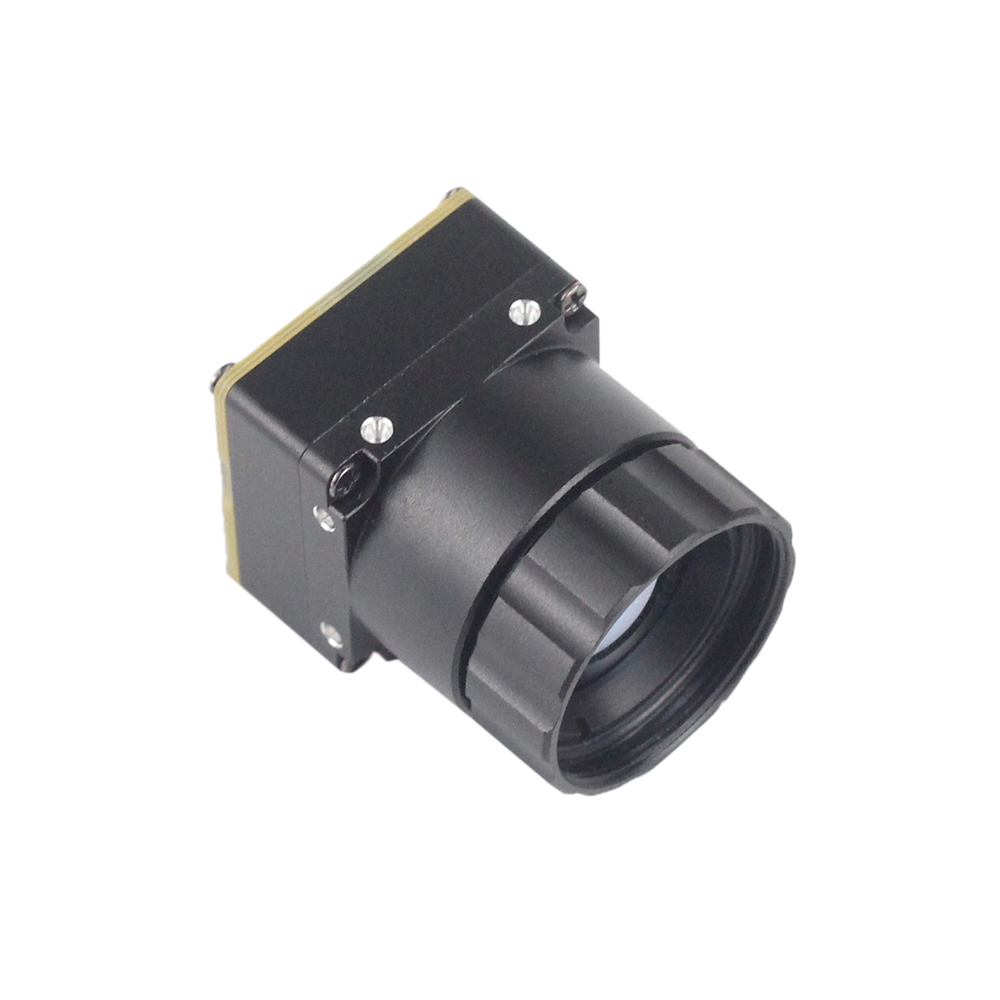
وحدة نواة كاميرا تصوير حراري مصغرة غير مبردة LWIR USB بدقة 640*512
الـ ميني 640 is an industrial powerhouse designed specifically for applications demanding dense pixel counts inside an ultra-compact 21mm × 21mm envelope. Pushing a native 640×512 resolution (with a software-selectable 640×480 crop mode via register), this core is built for aerial reconnaissance gimbals, perimeter security systems, and high-precision infrastructure inspection.
With a 12μm pixel pitch, this module resolves fine thermal gradients at substantial standoff ranges when paired with long-focus Germanium optics (from 5mm up to 150mm). Its single USB-C pipeline simultaneously delivers clean, uncompressed 14-bit/16-bit radiometric frames alongside register control through UVC Extension Units, making it an ideal choice when payload volume and gimbal balance are top priorities.

وحدة كاميرا حرارية مصغرة غير مبردة 384*288 للطائرات بدون طيار
الـ ميني 384 is the workhorse option for tight SWaP-C (Size, Weight, Power, and Cost) budgets. Built around an uncooled 384×288 VOx microbolometer array with an identical 12μm pitch and ≤40 mK thermal sensitivity, it strikes an optimal balance between low electrical load, minimal weight, and high radiometric performance.
What sets the Mini 384 apart in the field is its versatile interface set. It outputs analog CVBS video to link directly with legacy 5.8 GHz analog drone transmitters, while running standard USB-C UVC and serial SPI/UART interfaces for digital compute boards. It supports broad dual-gain temperature spans from -20°C up to +650°C, making it a reliable pick for electrical cabinet inspection, UAV search tasks, and predictive facility maintenance.
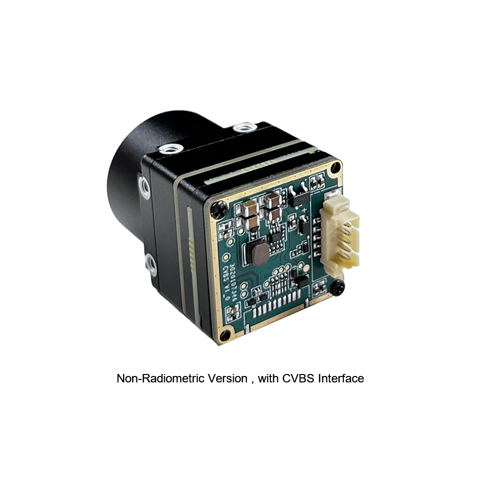
For detailed connector pin maps, mechanical mounting patterns, and driver configuration steps, check out our 384x288 thermal camera core integration manual.
مخطط تنفيذ ملموس: استخراج خام C++ وPython
Let's look at working code. Below are production-ready blueprints in both modern C++ and Python showing how to ingest a raw 16-bit radiometric stream and convert Digital Numbers (DN) into calibrated Celsius arrays without getting bogged down in user-space copy bottlenecks.
C++ Production Ingestion Engine
This C++ implementation targets the Linux Video4Linux2 (V4L2) backend in OpenCV, locking the capture node into raw 16-bit integer extraction mode (Y16 ) and executing the inverted Planck transformation:
#include <iostream>
#include <vector>
#include <cmath>
#include <opencv2/opencv.hpp>

// Factory-calibrated Planck coefficients (extracted from sensor EEPROM)
constexpr float SENSOR_PLANCK_B = 1428.0f;
constexpr float SENSOR_PLANCK_F = 1.0f;
constexpr float SENSOR_PLANCK_R = 224056.0f;

class ThermalCorePipeline {
public:
    explicit ThermalCorePipeline(int deviceIndex) {
        // Open the thermal core through standard Linux V4L2 capture
        captureNode.open(deviceIndex, cv::CAP_V4L2);
        if (!captureNode.isOpened()) {
            throw std::runtime_error("Sensor capture initialization failed: device node inaccessible.");
        }

        // Set FourCC to raw 16-bit linear integer stream (Y16)
        captureNode.set(cv::CAP_PROP_FOURCC, cv::VideoWriter::fourcc('Y', '1', '6', ' '));
        captureNode.set(cv::CAP_PROP_FRAME_WIDTH, 640);
        captureNode.set(cv::CAP_PROP_FRAME_HEIGHT, 512);
        captureNode.set(cv::CAP_PROP_CONVERT_RGB, false); // Preserve raw byte structures
    }

    // Convert raw 16-bit digital values to calibrated Celsius temperatures
    cv::Mat ExtractCelsiusMatrix(const cv::Mat& rawFrame, float emissivity = 0.97f) {
        cv::Mat celsiusMatrix(rawFrame.rows, rawFrame.cols, CV_32FC1);

        for (int row = 0; row < rawFrame.rows; ++row) {
            const uint16_t* rawDataPtr = rawFrame.ptr<uint16_t>(row);
            float* outputDataPtr = celsiusMatrix.ptr<float>(row);

            for (int col = 0; col < rawFrame.cols; ++col) {
                // Mask the 14-bit digital value, discarding ROIC telemetry flags
                uint16_t rawCount = rawDataPtr[col] & 0x3FFF;

                // Scale target flux using the target's emissivity coefficient
                float targetFlux = static_cast<float>(rawCount) / emissivity;

                // Invert the Planck equation to derive Kelvin temperature
                float kelvin = SENSOR_PLANCK_B / std::log((SENSOR_PLANCK_R / targetFlux) + SENSOR_PLANCK_F);

                // Convert Kelvin to Celsius
                outputDataPtr[col] = kelvin - 273.15f;
            }
        }
        return celsiusMatrix;
    }

    void ProcessNextFrame() {
        cv::Mat rawFrame;
        if (captureNode.read(rawFrame)) {
            cv::Mat calibratedCelsius = ExtractCelsiusMatrix(rawFrame);

            // Sample a 3x3 pixel area at the image center
            cv::Rect centerRegion(319, 255, 3, 3);
            cv::Scalar meanTemp = cv::mean(calibratedCelsius(centerRegion));

            std::cout << "[TELEMETRY] Central Region Temperature: "
                      << meanTemp[0] << " C" << std::endl;
        }
    }

    ~ThermalCorePipeline() {
        if (captureNode.isOpened()) {
            captureNode.release();
        }
    }

private:
    cv::VideoCapture captureNode;
};

int main() {
    try {
        ThermalCorePipeline pipeline(0);
        for (int i = 0; i < 30; ++i) {
            pipeline.ProcessNextFrame();
        }
    } catch (const std::exception& ex) {
        std::cerr << "Execution Fault: " << ex.what() << std::endl;
        return -1;
    }
    return 0;
}
Python Edge Radiometry Pipeline
For Python-centric setups, loop iteration is a performance killer. This script uses vectorized NumPy operations across the raw frame buffer to convert raw counts into temperature tensors at line rate:
import cv2
import numpy as np

def run_edge_radiometry_pipeline(device_id=0):
    # Initialize hardware capture node via Linux V4L2
    cap = cv2.VideoCapture(device_id, cv2.CAP_V4L2)

    # Request raw 16-bit radiometric transmission format (Y16)
    cap.set(cv2.CAP_PROP_FOURCC, cv2.VideoWriter_fourcc(*'Y16 '))
    cap.set(cv2.CAP_PROP_FRAME_WIDTH, 640)
    cap.set(cv2.CAP_PROP_FRAME_HEIGHT, 512)
    cap.set(cv2.CAP_PROP_CONVERT_RGB, 0)

    # Core calibration coefficients
    PLANCK_B = 1428.0
    PLANCK_F = 1.0
    PLANCK_R = 224056.0
    SURFACE_EMISSIVITY = 0.95

    try:
        while True:
            success, raw_buffer = cap.read()
            if not success or raw_buffer is None:
                print("Failed to acquire frame buffer from sensor core.")
                break

            # Mask status bits to isolate pure 14-bit digital numbers (DN)
            raw_counts = np.bitwise_and(raw_buffer, 0x3FFF).astype(np.float32)

            # Vectorized Planck inversion across the full sensor array
            adjusted_flux = raw_counts / SURFACE_EMISSIVITY
            kelvin_matrix = PLANCK_B / np.log((PLANCK_R / np.maximum(adjusted_flux, 1.0)) + PLANCK_F)
            celsius_matrix = kelvin_matrix - 273.15

            # Extract scene metrics
            peak_temp = np.max(celsius_matrix)
            mean_temp = np.mean(celsius_matrix)
            print(f"[EDGE TELEMETRY] Max Temp: {peak_temp:.2f} C | Mean Temp: {mean_temp:.2f} C")

            # Generate dynamic 8-bit visualization for monitoring
            norm_visual = cv2.normalize(celsius_matrix, None, 0, 255, cv2.NORM_MINMAX, dtype=cv2.CV_8U)
            colormap_preview = cv2.applyColorMap(norm_visual, cv2.COLORMAP_INFERNO)

            cv2.imshow("LWIR Radiometric Monitor", colormap_preview)
            if cv2.waitKey(1) & 0xFF == ord('q'):
                break
    finally:
        cap.release()
        cv2.destroyAllWindows()

if __name__ == "__main__":
    run_edge_radiometry_pipeline()
الانجراف الحراري، تخفيف زمن انتقال الغالق، وضبط NETD
In clean bench tests, thermal cameras look fantastic. But once you mount a module inside an enclosed carbon-fiber drone airframe or right next to an industrial servo drive, thermal drift becomes your number one problem. Because uncooled microbolometers do not have active cryogenic chillers, the sensor die continually exchanges thermal energy with the camera housing, optics, and nearby circuitry.
Mitigating Shutter Latency and Image Freezing
To re-zero pixel offset baselines, an uncooled core triggers an automated Non-Uniformity Correction (NUC). An internal solenoid snaps a mechanical shutter flag in front of the microbolometer array for 250 to 500 milliseconds. Every pixel samples this uniform thermal target, recalibrating individual offset coefficients.
The catch? During those 500 milliseconds, the video stream halts completely. If your drone is on a final autonomous descent vector or your ground robot is maneuvering around obstacles at speed, that sudden half-second visual blackout can cause state estimation drift or break visual feature tracking entirely.
Here is how we handle shutter latency out in the real world:
-
⚙️ Programmatic Shutter Locks: Turn off automatic background NUC cycles entirely by writing
SET_NUC_AUTO_MODE = 0via the SDK control interface. This puts the host software in control, allowing your flight computer to trigger a calibration pulse only during safe operational windows—such as stationary hovers or waypoints between inspection runs. - ⚙️ Shutterless Algorithmic Drift Compensation: For critical systems that cannot tolerate any blind spots, deploy shutterless correction modes. The SDK reads onboard thermistors on the lens cell and ROIC substrate, using a dynamic polynomial model to mathematically predict and zero out thermal drift across the array without ever dropping the mechanical shutter flag.
Optimizing Noise Equivalent Temperature Difference (NETD)
Noise Equivalent Temperature Difference (NETD) measures the smallest temperature delta the sensor can pull out of background noise. Both the Mini 640 and Mini 384 boast ratings of ≤40 mK in laboratory tests. But poor electrical and mechanical integration on a host carrier board can easily blow that out to a noisy 80 mK.
- ✅ Clean Carrier Board Power Delivery: High-frequency switching noise on 3.3V or 5V power rails readily injects noise into sensitive ROIC analog-to-digital converters. Feed the camera module from dedicated Low-Dropout (LDO) regulators, and keep high-frequency ripple below 15 mV RMS.
- ✅ Tuning Temporal Filter Coefficients: The SDK integrates configurable Infinite Impulse Response (IIR) and spatio-temporal recursive noise filters. Enabling these blocks cleans up high-frequency thermal noise across successive frames without blurring fast-moving targets across the field of view.

الأسئلة الشائعة الهندسية الشاملة
How does the thermal module SDK handle raw radiometric data extraction for accurate temperature analysis?
What platforms and hardware interfaces are supported for drone and embedded vision integration?
Can the thermal SDK execute Edge AI inference without causing high latency or CPU bottlenecks?
What is the mechanical shutter impact during real-time flight control, and how does the SDK bypass it?
عند إحكام إغلاق نواة حرارية غير مبردة داخل علبة مقاومة للطقس IP67/IP68، يكون التصميم الحراري السلبي حاسمًا لإيقاف الانحراف الحراري الأساسي وتدهور الصورة. لا تحتاج الميكروبولومترات إلى مبردات نشطة، لكن ASIC الصورة المدمجة ومشفرات الفيديو الشبكية تستهلك بين 1.0 واط و 2.5 واط أثناء التشغيل. في صندوق محكم ضيق بدون تدفق هواء، تخلق الحرارة الداخلية المحتبسة نقاطًا ساخنة عبر هيكل النواة ومصفوفة المستوى البؤري. تؤدي هذه التدرجات الحرارية الموضعية إلى خلل في قراءات درجة الحرارة الإشعاعية وتزيد من ضوضاء المستشعر، مما يقلل من حساسية NETD الفعالة لديك. لحل هذا، صمم مسارات مباشرة لتبديد الحرارة المعدنية—مثل كتلة باردة من الألومنيوم أو النحاس مقترنة بوسادات فجوة عالية التوصيل—تربط اللوحة الحرارية للوحدة مباشرة بالغلاف المعدني الخارجي. هذا يحول كامل الهيكل الخارجي إلى مشتت حراري كبير. أيضًا، تجنب تركيب أجزاء عالية الطاقة (مثل أجهزة الراديو RF أو محولات الطاقة الساخنة) بجوار النواة البصرية مباشرة للحفاظ على استقرار الظروف الحرارية عبر المستشعر.
- المعيار الصناعي: Wikipedia Infrared Imaging Physics & Bolometer Design
- Hardware Interconnects: Molex Micro-Miniature Interconnect Systems for Edge Devices
- دليل التكامل ذو الصلة: Complete 384x288 Thermal Camera Core Hardware Integration Guide
- Procurement Guide: Uncooled VOx Edge AI OEM Thermal Module Selection & Purchase Guide
- Architecture Review: دليل الوحدات الحرارية لعام 2025: تكامل سريع منخفض التكلفة للمهندسين