How Does a Thermographic Camera Work? The Complete Tech & Hardware Guide
2026年10月31日
Thermal Infrared Camera Guide: Working Principles, Resolution & Industrial Selection
Specifying an optical vision architecture for automated process diagnostics, aerospace payloads, or industrial machine vision is never as straightforward as swapping out standard digital cameras. While standard visual-band CMOS systems rely strictly on ambient photon reflection from target surfaces, an uncooled thermal infrared camera operates natively on passive radiant emittance. The sensor absorbs the thermodynamic flux radiated across the Long-Wave Infrared (LWIR) atmospheric transmission spectrum (8 to 14 micrometers) and maps it to a calibrated, two-dimensional spatial temperature profile. For an optical engineer or systems designer, selecting an OEM thermal engine requires balancing focal plane micro-architecture, pixel pitch limitations, Noise Equivalent Temperature Difference (NETD), readout electronics, and bus interface bandwidth against real-world mechanical constraints.
Choosing the wrong thermal core yields frustrating, expensive field failures: severe calibration drift across diurnal temperature swings, spatial smearing on moving parts, optical vignetting, and missing Johnson's Criteria recognition benchmarks at stand-off ranges. This technical selection manual walks through the core optoelectronic physics, microbolometer material science, optical diffraction tradeoffs, interface protocols, and real-world system engineering decisions required to integrate high-reliability thermal vision into factory lines, airborne gimbals, grid monitoring arrays, and robotic inspection platforms.
جدول المحتويات
- 👉 1. Optoelectronic Physics & LWIR Working Principles
- 👉 2. Detector Resolution, Pixel Pitch & Optical Range Dynamics
- 👉 3. Critical Performance Metrics: NETD, Frame Rates & Optics
- 👉 4. Industrial System Integration: Interfaces & Digital Protocols
- 👉 5. Industrial LWIR Product Comparison & Field Specifications
- 👉 6. Industrial & Autonomous Deployment Paradigms
- 👉 7. Frequently Asked Questions (Deep Technical Breakdown)
1. Optoelectronic Physics & LWIR Working Principles
Every physical object with a thermodynamic temperature above absolute zero (0 Kelvin, or -273.15°C) radiates electromagnetic energy. This radiation originates from microscopic thermal agitation among the material's constituent atoms, ions, and molecules. Unlike visual image sensors that measure electron-hole pairs generated by incoming light in the narrow visible (0.38 to 0.75 μm) and near-infrared (0.75 to 1.0 μm) bands, an uncooled thermal infrared camera detects the thermal energy self-emitted by the target scene. Designing a system that measures these emissions accurately starts with the fundamental mathematical laws of radiative heat transfer.
Planck’s Radiation Distribution and Stefan-Boltzmann Emittance
The spectral distribution of electromagnetic power radiated per unit area of an ideal blackbody radiator across all directions is governed by Planck’s Radiation Law:
In this expression, h is Planck’s constant (6.626 × 10⁻³⁴ جول·ثانية)،, c is the speed of light through a vacuum (2.998 × 10⁸ متر/ثانية)،, kB represents the Boltzmann constant (1.381 × 10⁻²³ J/K), λ هو الطول الموجي للانبعاث الكهرومغناطيسي، و T is the target surface temperature in Kelvin. Integrating Planck’s spectral radiant exitance over all possible wavelengths yields the Stefan-Boltzmann Law:
هنا،, ي* represents total hemispherical radiant emittance (W/m2), ε is target surface emissivity (ranging from 0.0 for a pristine polished mirror to 1.0 for a theoretical blackbody cavity), and σ is the Stefan-Boltzmann constant (5.670 × 10⁻⁸ واط·متر-2·كلفن-4). In practical deployments, material emissivity fluctuates significantly across a surface. Clean, polished metals exhibit very low emissivity (ε ≈ 0.04 to 0.12) paired with high specular reflectance, while printed circuit boards, polymers, motor casings, and rubberized cable insulation show high emissivity (ε ≈ 0.90 to 0.97).
Wien’s Displacement Law demonstrates that the peak wavelength of radiant emission moves inversely with absolute temperature: λmax = 2897.8 / T (μm·K). For ambient terrestrial scenarios where machines, structures, and humans sit between -20°C and +120°C (253 K to 393 K), peak thermodynamic flux lands squarely between 7.3 μm and 11.4 μm. For this reason, uncooled industrial thermal imagers prioritize the Long-Wave Infrared (LWIR) atmospheric transmission window (8.0 to 14.0 μm). In this transmission band, molecular absorption from water vapor (H2O) and carbon dioxide (CO2) drops considerably, letting emitted thermal photons travel long distances through ambient air with low attenuation. Foundational research in infrared imaging science highlights that this specific atmospheric window offers consistent penetration through suspended aerosols, thick dust clouds, and heavy smoke.
بنية مصفوفة المستوى البؤري (FPA) للميكروبولومتر
Cooled scientific and military cameras employ photon detectors (such as InSb or MCT) that require cryogenic cooling engines to reach 77 Kelvin. While these systems deliver blistering capture speeds, their high power draw, moving mechanical parts, and limited compressor runtimes make them ill-suited for continuous industrial duty. Industrial systems instead rely on uncooled microbolometer Focal Plane Arrays (FPAs). These sensors run reliably at ambient temperature without complex cooling hardware, drawing minimal power while delivering mean time between failures (MTBF) exceeding 30,000 to 50,000 continuous hours.
An uncooled microbolometer array consists of a micro-machined two-dimensional matrix of pixel bridges suspended over a CMOS silicon substrate. Each pixel is fabricated as an elevated micro-membrane isolated from the underlying Readout Integrated Circuit (ROIC) by two structural anchor legs. These legs are thin, high-aspect-ratio beams composed of low-thermal-conductivity materials like silicon nitride (Si3N4). The suspended membrane incorporates an infrared absorbing cap bonded to a thin-film thermistor layer.
When target LWIR photons pass through a specialized Germanium lens assembly, they hit the microbolometer membrane. The material absorbs the energy, raising the membrane temperature by fractions of a milliKelvin. This temperature shift directly alters the electrical resistance of the thermistor layer. The thermal time constant of this cycle (heating, resistance measurement, and heat dissipation down the support legs) typically measures between 8 and 14 milliseconds. This physical thermodynamic behavior sets the upper boundary for uncooled microbolometer frame rates.
Vanadium Oxide (VOx) vs. Amorphous Silicon (α-Si)
The thin-film thermistor material embedded within the microbolometer structure determines the sensor's electronic noise floor, thermal sensitivity, and temporal response. Modern commercial production relies on two competing semiconductor materials:
- ⚙️
أكسيد الفاناديوم (VOx): VOx is the industry standard for high-reliability industrial automation, defense systems, and aerial payloads. It features a high Temperature Coefficient of Resistance (TCR), generally between -2.0% and -3.0% per degree Celsius at nominal temperatures. Crucially, VOx exhibits lower 1/f electronic flicker noise when driven with low microbolometer bias voltages. This quiet baseline allows VOx sensors to hit sensitivity ratings below 35 mK NETD. Depositing stoichiometric VOx requires tight vacuum control, but it yields consistent radiometric precision and minimal drift across broad operational spreads (-40°C to +85°C).
- ⚙️
السيليكون غير المتبلور (α-Si): Amorphous Silicon is often used in high-volume, budget-sensitive thermal sensors because it can be deposited directly using standard silicon CMOS foundry workflows. While α-Si provides a solid TCR (-2.5% to -4.0%/°C), its higher 1/f noise floor and bulk resistance present real operational challenges. Consequently, α-Si sensors often struggle to break below 50 mK to 70 mK NETD without lengthy pixel integration times, which can introduce motion artifacts. For high-speed lines, precision thermal metrology, and high-contrast edge classification, VOx remains the preferred platform.
For an in-depth review of semiconductor physics, bridge geometry, and radiometric calibration routines, read our companion engineering guide on infrared thermography technology.
2. Detector Resolution, Pixel Pitch & Optical Range Dynamics
In the visual camera market, multi-megapixel CMOS sensors are ubiquitous and inexpensive. In uncooled thermal infrared imaging, however, native pixel counts are significantly lower. This difference stems from the mechanical complexity of MEMS vacuum packaging, the longer wavelengths involved, and the physical surface area needed to capture sufficient thermal photon flux without drowning the signal in thermal background noise. Picking the right resolution tier and pixel pitch requires balancing target optical stand-off distances against hardware integration limits.
Resolution Tiers in Industrial Machine Vision
Uncooled microbolometer arrays are broadly organized into four distinct resolution classes:
- ⚙️
Entry-Level Diagnostics (160×120 to 256×192): 19,200 to 49,152 active pixels. Suitable for basic presence detection, gross mechanical hotspot locating, or close-range diagnostic attachments. They lack the spatial fidelity needed to run automated contour segmentation or isolate distant anomalies.
- ⚙️
Mid-Range Inspection (384×288): 110,592 active pixels. A widely deployed legacy format found in switchgear inspection boxes, localized furnace monitoring, and warehouse AGV proximity tracking.
- ⚙️
High-Resolution Industrial Standard (640×512): 327,680 active pixels. The workhorse tier for automated defect detection, UAV perimeter gimbals, search-and-rescue arrays, and municipal utility inspection. A 640×512 array offers an optimal balance between spatial sharpness, video bus bandwidth, and computing loads for real-time edge AI inference.
- ⚙️
Ultra-High-Resolution Megapixel LWIR (1280×1024): 1,310,720 active pixels. The state-of-the-art for commercial uncooled FPAs. Delivering four times the active area of a 640×512 core, this format allows systems to monitor wide industrial sectors, execute stand-off border interdiction, and inspect dense printed circuit boards without requiring complex mechanical pan-tilt stages.
The Shift to 12μm Pixel Pitch: Optical Trade-Offs & Diffraction Limits
For years, microbolometer manufacturing was built around 25 μm and 17 μm pixel architectures. Today, improvements in wafer-level packaging (WLP) and fine-pitch lithography have made 12 μm pixel pitch arrays the primary standard, with foundries developing 10 μm and 8 μm variants. While tighter pixel pitch provides undeniable physical packaging advantages, it alters system optical engineering in fundamental ways:
Size, Weight, and Power (SWaP) Reduction: Sensor active diagonal scales directly with pixel pitch. A 640×512 sensor built on a 17 μm process has a physical diagonal of roughly 13.88 mm. Shrinking that array to a 12 μm pitch drops the diagonal to approximately 9.80 mm—a 30% reduction. Because optical lens mass scales non-linearly with aperture diameter, smaller sensor diagonals allow engineers to achieve the same angular field of view (FOV) using substantially smaller Germanium optical assemblies. The resulting 40% to 60% mass savings is invaluable for weight-constrained airborne payloads and compact robotic arms.
Diffraction Limits and the Airy Disk: In standard visual optics, the central light wavelength (~0.5 μm) is vastly smaller than the physical pixel size. In the LWIR domain, the operating wavelength (λ ≈ 10 μm) is nearly identical to the size of a modern 12 μm pixel. Diffraction through a round lens aperture forms a blurred central spot known as the Airy disk. The physical diameter of this central disk is defined by:
For an f/1.0 optical assembly focusing a 10 μm wavelength, the central Airy spot diameter spans 24.4 μm. On a 12 μm detector, that central spot covers more than a 2×2 pixel cluster. Even with an ideal, aberration-free optic, optical diffraction sets a hard limit on visual clarity. Furthermore, a smaller 12 μm pixel collects fewer photons per frame than an older 17 μm unit. To prevent sensitivity loss, 12 μm microbolometer cores must use higher-grade VOx films, lower-noise ROIC amplifiers, and high-transmittance f/1.0 lenses to collect sufficient photon volume.
Optical Range Dynamics: Instantaneous Field of View & Johnson's Criteria
When selecting optics, engineers must calculate the system's Instantaneous Field of View (IFOV). This parameter defines the angle subtended by a single detector pixel through the optical lens:
حيث p represents the microbolometer pixel pitch in millimeters and f is the lens focal length in millimeters, giving the resulting IFOV in milliradians (mrad). Multiplying the calculated IFOV by target distance gives the physical ground footprint covered by a single pixel.
To confirm that a camera and lens pair will deliver the required target clarity, engineers cross-reference the pixel footprint against Johnson’s Criteria. This framework outlines the minimum number of resolved 50% contrast line-pairs required across a target's critical dimension (commonly 0.75 meters for a human and 2.3 meters for an industrial vehicle) to carry out a given monitoring task:
- ⚙️
Detection (0.75 line-pairs ≈ 1.5 pixels): An operator or tracking model detects that an object of interest is present within the background scene.
- ⚙️
Recognition (3.0 line-pairs ≈ 6.0 pixels): The target class can be verified (for instance, distinguishing an autonomous transport vehicle from a maintenance worker).
- ⚙️
Identification (6.0 line-pairs ≈ 12.0 pixels): The exact target type or fault condition can be confirmed (such as distinguishing an authorized repair truck from an unknown vehicle, or spotting a fractured busbar clamp versus normal operational heating).
As an example: consider a 1280×1024 thermal camera with a 12 μm pixel pitch fitted with a 25 mm objective lens. The calculated IFOV is 0.012 / 25 = 0.48 mrad. At an inspection distance of 500 meters, one individual pixel covers 0.24 meters. A vehicle with a 2.3-meter critical dimension covers 9.58 pixels across (representing 4.79 line pairs)—comfortably exceeding the threshold for reliable recognition. Running these calculations early guarantees that the chosen lens and sensor combination will meet operational field requirements.
3. Critical Performance Metrics: NETD, Frame Rates & Optics
Headline resolution figures tell only part of the story. System performance depends heavily on three interrelated optoelectronic parameters: Noise Equivalent Temperature Difference (NETD), temporal frame acquisition rate, and the optical assembly's thermal stability across varying conditions.
فرق درجة الحرارة المكافئ للضوضاء (NETD)
NETD is the fundamental metric used across the thermal imaging industry to quantify sensor sensitivity. Expressed in millikelvins (mK), it indicates the target temperature difference that generates an electrical signal equal to the sensor's baseline noise floor (a Signal-to-Noise Ratio of 1) at the readout output:
حيث Vn represents the root-mean-square (RMS) electronic noise floor within the sensor circuitry (combining Johnson-Nyquist noise, thermal fluctuation noise, and ROIC digitizing noise), while dV/dT describes the radiometric signal voltage swing per unit change in target blackbody temperature. A lower numerical NETD rating indicates a more sensitive thermal core.
In demanding factory automation applications, a thermal sensor with an NETD ≤ 30 mK to 40 mK reliably detects temperature deltas as fine as 0.03°C. This sensitivity is vital for catching early dielectric breakdown across high-voltage ceramic insulators, spotting micro-voids inside multi-layer composite panels, or finding hairline soldering defects. By contrast, lower-grade microbolometers with an NETD of 60 mK to 100 mK struggle in low-contrast, isothermal scenes: the output dissolves into grainy, mottled noise, causing downstream computer vision models to miss subtle defects or throw false positives.
Temporal Frame Rates: Industrial Automation vs. Export Restrictions
High-performance thermal cameras are governed by strict international export controls. Under the Wassenaar Arrangement and United States International Traffic in Arms Regulations (ITAR), thermal cores that refresh faster than 9 Hz are classified as dual-use goods. Because of this, consumer-grade thermal units and entry-level inspection tools are intentionally hard-locked to an export-exempt 9 Hz (or 8.3 Hz) refresh rate.
For factory automation, automated sorting bins, aerial gimbals, and mobile robotics, a 9 Hz stream is unusable. Rapidly moving components on a conveyor show heavy motion blur, while drone gimbals suffer from rolling distortion and frame lag that can destabilize tracking loops. Industrial OEM cores address this by providing continuous 25 Hz, 30 Hz, 50 Hz, or 60 Hz capture rates. These higher frame rates keep video latency under 30 milliseconds, eliminate fast-motion artifacts, and feed smooth, reliable visual data into embedded machine learning pipelines.
Radiometric Non-Uniformity Correction (NUC) and Athermalized Optics
Uncooled microbolometers are inherently vulnerable to non-uniformity drift. Each tiny microbolometer bridge has subtle variations in its resistance, thermal mass, and circuit traces. Without real-time corrections, these variations create Fixed Pattern Noise (FPN)—a distinct, static grid pattern overlaid across the live video. Maintaining image fidelity requires proven correction strategies:
- ⚙️
تصحيح عدم التجانس بالغالق الميكانيكي: A small internal solenoid flips a uniform-temperature, high-emissivity paddle between the lens optics and the microbolometer array for roughly 100 to 250 milliseconds. The onboard processor reads this uniform reference field, recalculates offset coefficients for every pixel, and updates the active look-up table (LUT). While this approach provides solid baseline accuracy, the temporary video freeze can disrupt fast feedback loops.
- ⚙️
التصحيح الخوارزمي بدون مصراع (NUC): Advanced cores run intelligent, shutter-free correction algorithms. By reading internal thermistors mounted across the chassis, lens barrel, and FPA substrate, onboard firmware dynamically adjusts pixel calibration curves in real time. This keeps the image uniform without mechanical clicks or frozen video frames.
- ⚙️
Athermalized Optical Assemblies: Standard glass completely blocks LWIR wavelengths. Thermal lenses must be diamond-turned from optical-grade Germanium (Ge), Zinc Selenide (ZnSe), or Chalcogenide glass. Germanium has a massive refractive index temperature coefficient (dn/dT ≈ 400 × 10-6/°C), meaning an uncompensated lens will quickly drift out of focus as ambient temperatures change. Industrial lenses employ passive mechanical athermalization, pairing high-expansion aluminum with low-expansion Invar collars to mechanically compensate for optical focus shifts across temperatures from -40°C to +80°C.
For more details on evaluating MTF curves, optical sensitivity benchmarks, and core integration, see our dedicated guide to evaluating OEM thermal camera modules.
4. Industrial System Integration: Interfaces & Digital Protocols
A capable microbolometer sensor core is only as useful as the communications bus carrying its data. Streaming raw 14-bit or 16-bit radiometric frame data to an embedded host requires selecting an interface architecture tailored to your platform's processing power, wiring runs, and latency budget.
Networked Video Transport: RJ45, RTSP, and ONVIF Compliance
For perimeter monitoring, substation installations, and broader plant facilities, Ethernet-based networking is typically the easiest interface to deploy. OEM cores equipped with an RJ45 Gigabit Ethernet port utilize onboard image processing engines that compress raw sensor readings into network-friendly H.264, H.265, or Motion-JPEG video streams.
By implementing Real-Time Streaming Protocol (RTSP) along with ONVIF Profile S and Profile T standards, these network-ready modules tie cleanly into existing Video Management Systems (VMS), Network Video Recorders (NVRs), and industrial SCADA platforms. System integrators can monitor real-time visual feeds while querying radiometric spot temperatures, regional min/max data, and system health via JSON-RPC, MQTT, or Modbus TCP commands over standard industrial Ethernet lines up to 100 meters long.
Low-Latency Raw Ingestion: MIPI-CSI2, CMOS Parallel, and USB-C
In autonomous drones, robotics, and fast closed-loop control systems, standard video compression latency (which commonly introduces 60 to 180 ms of pipeline lag) can degrade control stability. These setups require direct, uncompressed sensor streaming:
- ⚙️
MIPI-CSI2: Modern edge-computing platforms (including NVIDIA Jetson Orin, NXP i.MX8, and Rockchip processors) include native MIPI Camera Serial Interface ports. A MIPI-CSI2 link streams raw 14-bit radiometric frames straight into the system's hardware image signal processor memory over high-speed differential pairs, maintaining end-to-end processing latency below 10 milliseconds.
- ⚙️
Parallel Digital CMOS / LVDS: Vision capture cards and FPGAs often employ parallel digital or Low-Voltage Differential Signaling (LVDS) lines. This raw bus exposes pixel clock, line synchronization, and parallel data lines, enabling FPGA engineers to execute custom hardware-level image filters (such as real-time edge detection or automated particle tracking) with zero operating system overhead.
- ⚙️
USB Video Class (UVC / USB 3.0): For test benches, field diagnostic meters, and laboratory workstations, USB-C provides simple plug-and-play operation. Operating under standard UVC specifications, the camera streams calibrated radiometric frames directly into Linux, Windows, or Android environments without requiring proprietary third-party drivers.
Mechanical Routing & Multi-Axis Gimbal Considerations
Routing wide-bandwidth digital buses through rotating gimbals and robotic joints presents notable mechanical challenges. Standard ribbon cables or twisted pairs fatigue over time, crack under continuous rotation, and emit electromagnetic interference (EMI) inside compact enclosures. Experienced aerospace engineers route differential signals through fine-gauge Micro Coaxial Cable assemblies. These ultra-flexible micro-coax bundles provide consistent 50-ohm impedance matching and full shielding, carrying high-frequency thermal video through 360-degree slip rings cleanly without packet drops or signal degradation.
For systems designers working on handheld diagnostic devices or ultra-compact assemblies, explore our technical breakdown on compact portable USB thermal camera architectures.
5. Industrial LWIR Product Comparison & Field Specifications
To help engineers choose between high-definition fixed surveillance systems and lightweight drone-compatible camera cores, we examine two purpose-built uncooled thermal imaging solutions below.
كاميرا تصوير حراري عالية الدقة غير مبردة بالأشعة تحت الحمراء 1280*1024 LWIR
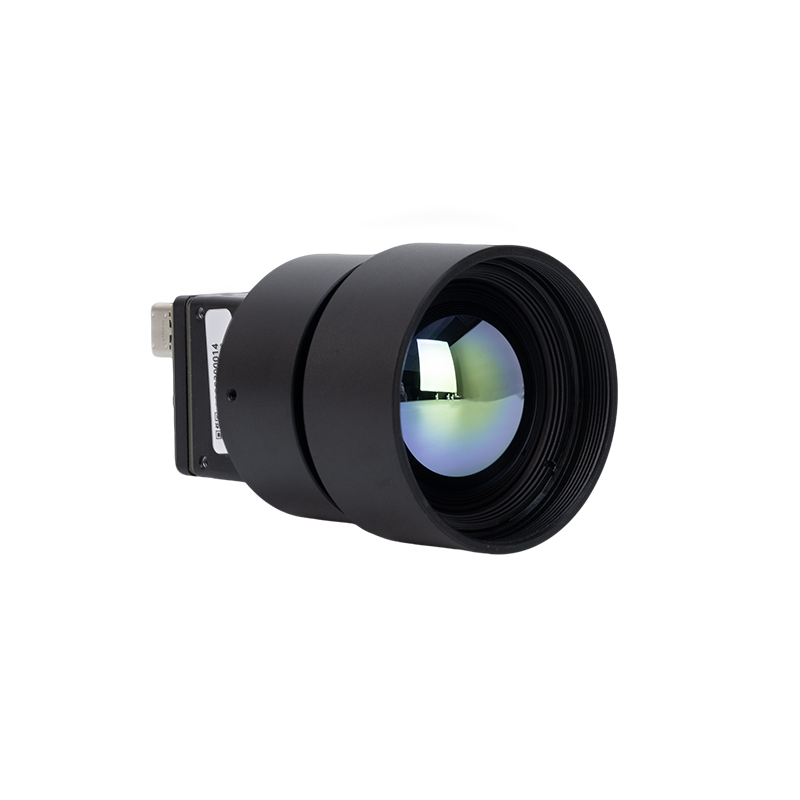
الـ كاميرا تصوير حراري عالية الدقة غير مبردة بالأشعة تحت الحمراء 1280*1024 LWIR is built for expansive perimeter protection, defense installations, critical asset tracking, and laboratory-grade automated thermal inspection. Featuring an active 1.3-megapixel detector matrix, this engine covers broad geographic areas while capturing subtle, distant anomalies with remarkable edge definition.
- ✅
True Megapixel Array Resolution: 1280×1024 uncooled microbolometer sensor providing 1,310,720 active measurement pixels for extended Johnson's Criteria reach.
- ✅
Germanium Prime Optical Assembly: Fitted with an engineered 25mm prime Germanium lens optimized for maximum LWIR optical transmission.
- ✅
Sub-35mK NETD Sensitivity: Reliably isolates subtle thermal shifts, micro-fractures, and hidden insulation voids across wide operational areas.
- ✅
Ruggedized Industrial Housing: Designed with a precision-machined athermalized chassis to prevent focal shift across demanding field environments.
وحدة كاميرا استشعار حراري غير مبردة RJ45 CVBS RTSP IP بدقة 640*512
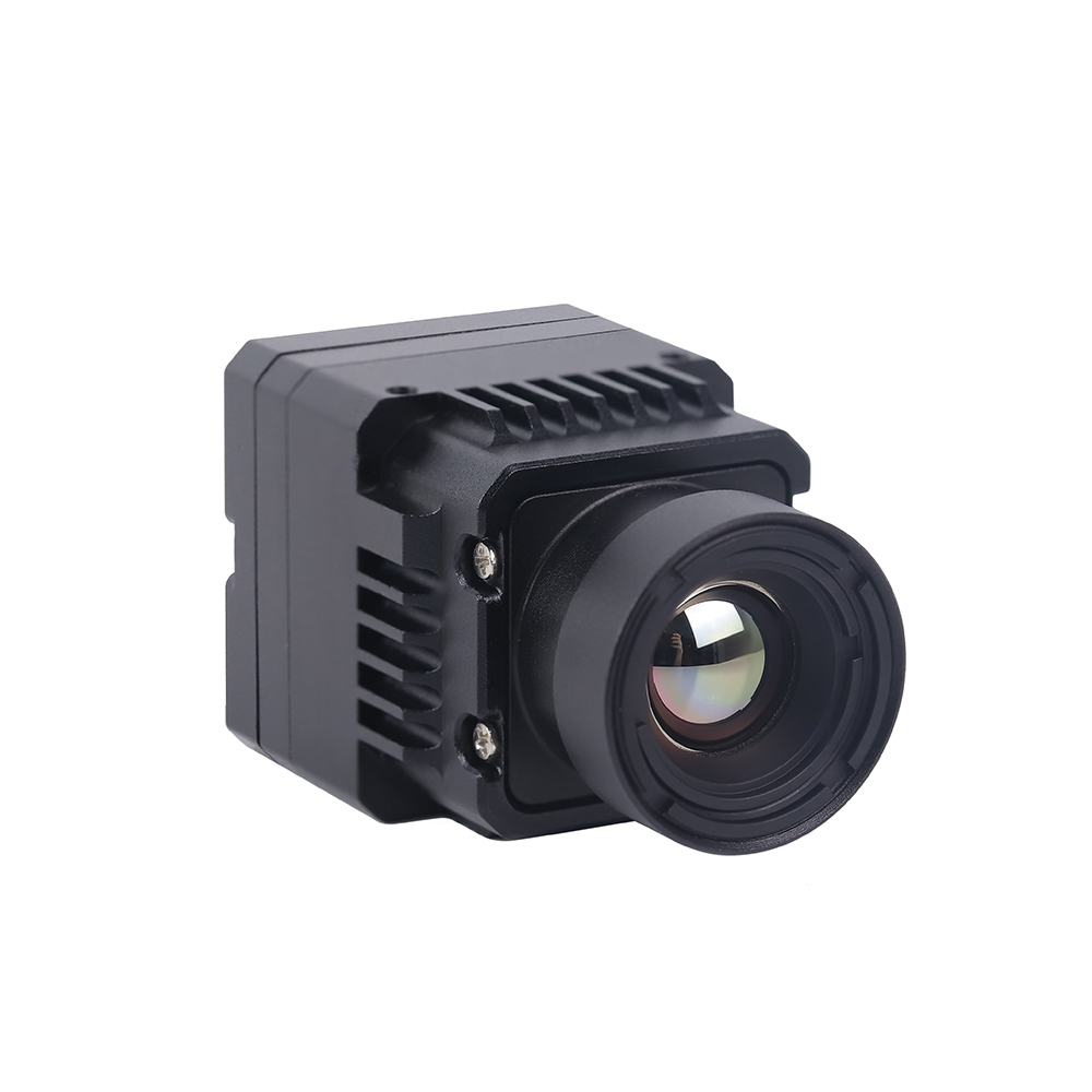
الـ وحدة كاميرا استشعار حراري غير مبردة RJ45 CVBS RTSP IP بدقة 640*512 is a SWaP-optimized core tailored specifically for drone payloads, autonomous mobile robots (AMRs), and industrial IoT inspection points. Driven by a dedicated ASIC, this unit packages edge video processing, high thermal sensitivity, and simultaneous digital/analog output into a compact footprint.
- ✅
Onboard ASIC Video Engine: Integrates a power-efficient ASIC executing real-time Non-Uniformity Correction (NUC), Digital Detail Enhancement (DDE), and noise filtering.
- ✅
Dual Concurrent Outputs: Provides an RJ45 Ethernet port supporting RTSP/ONVIF IP streaming alongside an analog CVBS feed for zero-latency pilot control.
- ✅
Optimized SWaP Architecture: Ultra-compact dimensions and low electrical power consumption maximize flight battery life on small unmanned aerial vehicles (UAVs).
- ✅
ميكروبولومتر عالي الحساسية: Delivers ≤ 40 mK thermal resolution to detect minute anomalies even under adverse atmospheric conditions.
Comprehensive Technical Specifications Comparison
| المعلمة التقنية | 1280×1024 Megapixel LWIR Core | 640×512 Mini ASIC Drone Module |
|---|---|---|
| FPA Array Resolution | 1280 × 1024 Pixels (1,310,720 pixels) | 640 × 512 Pixels (327,680 pixels) |
| مادة الكاشف | ميكروبولومتر أكسيد الفاناديوم (VOx) غير المبرد | ميكروبولومتر أكسيد الفاناديوم (VOx) غير المبرد |
| Spectral Operational Band | 8 – 14 μm (Long-Wave Infrared) | 8 – 14 μm (Long-Wave Infrared) |
| الحساسية الحرارية (NETD) | ≤ 35 م كلفن (@ 25°م، f/1.0) | ≤ 40 mK (@ 25°C, f/1.0) |
| التكوين البصري | 25mm High-Transmittance Germanium Prime Optic | Interchangeable Athermalized Drone Mount Lens |
| واجهات الفيديو الأساسية | High-Speed Parallel Digital / LVDS / Custom Serial | RJ45 (Ethernet RTSP/IP, ONVIF) + CVBS Analog |
| Primary Processing Pipeline | High-Throughput FPGA + 14-bit Radiometric Stream | Dedicated Ultra-Low-Power Image Processing ASIC |
| Primary Deployment Sectors | Perimeter security, critical infrastructure, metrology | UAV/UAS drone gimbals, robotic systems, factory IoT |
6. Industrial & Autonomous Deployment Paradigms
The operational characteristics of uncooled thermal camera modules allow engineers to implement continuous, non-contact monitoring systems across a range of industrial, municipal, and autonomous hardware platforms.
Aerial Robotics, Drone Payloads & Electrical Grid Inspection
Electrical transmission networks spanning rugged geography require frequent surveys to catch deteriorating hardware before major power failures occur. Integrating the وحدة RJ45 CVBS RTSP IP غير المبردة بنواة 640*512 into an airborne gimbal gives operators a capable, lightweight inspection solution. By keeping weight to a minimum, aircraft endurance remains intact while providing two independent video streams: zero-latency CVBS analog video transmits over 5.8 GHz links to the pilot's control screen, while the onboard autopilot processes the digital RTSP IP stream to automatically center on conductors and insulators.
Corroded splice points, cracked bushings, and loose clamp junctions generate measurable thermal patterns long before they burn out. The sensor's ≤ 40 mK thermal sensitivity and calibrated optics enable drone teams to identify temperature rises of under 1°C from 30 to 50 meters away, keeping crews away from energized transmission lines.
Automated Electronics Quality Assurance & PCB Thermal Profiling
As modern Surface-Mount Technology (SMT) migrates toward micro-pitch Ball Grid Arrays (BGAs) and integrated power modules, physical contact probes become impractical. A contact thermocouple acts as an unintentional heat sink, draining heat away from tiny solder pads and skewing the temperature readings.
Positioning the High Resolution 1280*1024 LWIR Camera with its 25mm Prime Lens over automated test stations allows non-contact, micro-scale inspection of live circuit boards under dynamic loads. With 1.3 million radiometric pixels, the sensor resolves individual thermal boundaries across 0402 and 0201 passive components, pinpointing bonding failures, poor solder joints, and localized silicon trace shorts. Machine vision software compares the live thermal signature against an approved baseline template, automatically shunting defective boards to rework lines before protective conformal coating is applied.
Autonomous Early Fire Prevention in Energy Storage and Waste Management
Commercial Battery Energy Storage Systems (BESS) using lithium chemistries face the persistent risk of thermal runaway triggered by manufacturing flaws, separator breakdown, or overcharging. Standard optical smoke sensors or air aspirators trigger only after a cell vents hot gas and smoke—by which point fire suppression becomes significantly harder.
Networked 640×512 or 1280×1024 thermal infrared cameras provide an effective non-contact safety barrier. Running 24/7, the thermal cores continuously inspect the outer faces of battery racks. If a battery module exceeds safe operating thresholds (such as 55°C) or exhibits a temperature climb faster than 3°C per minute, the thermal engine automatically triggers an industrial Ethernet alarm. This early notification allows systems to isolate the battery bank and activate cooling systems minutes before off-gassing begins, preventing catastrophic damage.
7. Frequently Asked Questions (Deep Technical Breakdown)
What is the exact optoelectronic difference between a near-infrared camera and a thermal infrared camera?
In contrast, a true thermal infrared camera operates across the Mid-Wave (MWIR, 3–5 μm) or Long-Wave Infrared (LWIR, 8–14 μm) bands, utilizing uncooled microbolometers (VOx, α-Si) or cooled quantum detectors. These sensors operate on Planck's radiation law, directly absorbing the passive thermodynamic radiant flux emitted by an object's kinetic molecular activity. A thermal camera requires zero external lighting, seeing through complete darkness, light rain, industrial dust, and heavy chemical smoke while generating calibrated temperature data.
Why are low-cost consumer thermal cameras unsuitable for professional industrial automation and OEM integration?
Second, budget devices show poor thermal sensitivity, with NETD figures often sitting around 70 mK to 100 mK or higher. This high electronic noise floor drowns out subtle thermal changes, leaving the system blind to early bearing fatigue, slight phase resistance imbalances, or trace circuit defects.
Third, consumer units use uncalibrated plastic or chalcogenide optics in uncompensated barrels. As ambient temperatures fluctuate, temperature measurements can drift by ±5°C to ±10°C. In contrast, industrial-grade thermal cores use calibrated Vanadium Oxide FPAs with passively athermalized Germanium lenses, shutter-based Non-Uniformity Correction (NUC), high 30–60 Hz frame rates, and deterministic industrial interfaces (Gigabit Ethernet RTSP/ONVIF, MIPI-CSI2, CVBS), delivering repeatable temperature data within ±2°C across demanding conditions.
How does a radiometric thermal infrared camera calculate absolute temperature without physical contact?
To calculate true surface temperature from this raw digital output, onboard processing applies the fundamental radiometric radiation balance equation:
Wالإجمالي = ε τ Wالهدف + (1 - ε) τ Wالمنعكس + (1 - τ) Wالجوي
حيث ε is target emissivity, τ is atmospheric transmission, Wالهدف is radiant flux emitted by the target, Wالمنعكس is ambient thermal radiation reflecting off the target surface, and Wالجوي is energy radiated directly by the intervening air volume.
By isolating Wالهدف and running it against factory-calibrated polynomial response tables derived from laboratory blackbody standards across multiple temperature spans, the onboard processor solves the inverse of Planck's Radiation Law in real time. This delivers a calibrated surface temperature for each individual pixel across the matrix, compensating for ambient reflections and atmospheric absorption.
عند إحكام إغلاق نواة حرارية غير مبردة داخل علبة مقاومة للطقس IP67/IP68، يكون التصميم الحراري السلبي حاسمًا لإيقاف الانحراف الحراري الأساسي وتدهور الصورة. لا تحتاج الميكروبولومترات إلى مبردات نشطة، لكن ASIC الصورة المدمجة ومشفرات الفيديو الشبكية تستهلك بين 1.0 واط و 2.5 واط أثناء التشغيل. في صندوق محكم ضيق بدون تدفق هواء، تخلق الحرارة الداخلية المحتبسة نقاطًا ساخنة عبر هيكل النواة ومصفوفة المستوى البؤري. تؤدي هذه التدرجات الحرارية الموضعية إلى خلل في قراءات درجة الحرارة الإشعاعية وتزيد من ضوضاء المستشعر، مما يقلل من حساسية NETD الفعالة لديك. لحل هذا، صمم مسارات مباشرة لتبديد الحرارة المعدنية—مثل كتلة باردة من الألومنيوم أو النحاس مقترنة بوسادات فجوة عالية التوصيل—تربط اللوحة الحرارية للوحدة مباشرة بالغلاف المعدني الخارجي. هذا يحول كامل الهيكل الخارجي إلى مشتت حراري كبير. أيضًا، تجنب تركيب أجزاء عالية الطاقة (مثل أجهزة الراديو RF أو محولات الطاقة الساخنة) بجوار النواة البصرية مباشرة للحفاظ على استقرار الظروف الحرارية عبر المستشعر.
- المعيار الصناعي: Wikipedia Infrared Imaging Physics & Overview
- Signal Integrity & Wiring: Micro Coaxial Cable Transmission Lines for Gimbal Payloads
- دليل ذو صلة: Infrared Thermography Working Principles & Sensor Architecture
- دليل ذو صلة: OEM Thermal Camera Module Technical Selection & Integration
- دليل ذو صلة: Compact Portable USB Thermal Camera Modules & Architectures