Commercial Infrared Camera Guide: AI Thermal Imaging vs Near Infrared Solutions
2026年8月7日
High-Performance Infrared Core Guide: Compact LWIR Modules for OEM & Drones
2026年8月10日
OEM Thermal Core Selection & Upgrade Guide: High-Resolution LWIR Modules for Integrators
If you've ever tried cramming an infrared sensor payload into a tight gimbal frame or a portable scope, you already know the engineering drill. Integrating a high-performance thermal core into compact hardware—whether we're talking about small unmanned aerial vehicles (sUAVs), tactical optics, automated factory inspection rigs, or high-end security gimbals—is always a high-wire balancing act. You're constantly trading off spatial resolution and thermal sensitivity against brutal Size, Weight, Power, and Cost (SWaP-C) limits. As uncooled Long-Wave Infrared (LWIR) microbolometers leap from old-school 320×240 pixel arrays to ultra-dense 640×512 and megapixel-class 1280×1024 focal plane arrays (FPAs), the engineering math gets complicated fast. Pick the wrong core, and you're stuck dealing with thermal defocus, dropped frames, or a battery that drains in twenty minutes. Selecting the right thermal core means rolling up your sleeves and looking past the marketing datasheet: you need to evaluate actual microbolometer pitch (down to 12µm or sub-10µm), real-world Noise Equivalent Temperature Difference (NETD), optical modulation transfer function (MTF), and digital video transport lines.
Upgrading a legacy electro-optical rig or building a next-gen thermal system from scratch takes a lot more than just plugging in a sensor. It requires an intimate, hands-on understanding of modern hardware interfaces—think direct MIPI-CSI2, DVP, and UVC-compliant USB connections—alongside the heavy lifting done by onboard image signal processing (ISP) pipelines. Look, this guide isn't theoretical filler. It's a practical technical blueprint built for optical engineers, embedded systems architects, and defense/industrial OEMs who need to evaluate, retrofit, and deploy high-resolution uncooled LWIR thermal core modules. By digging into sensor physics, thermal dissipation strategies, AI-driven ISP architectures, real-world spec benchmarks, and concrete integration protocols, your engineering team can cut out the guesswork, shorten development cycles, and get maximum image fidelity and radiometric accuracy out into the field.
Table of Contents
- 👉 1. Uncooled LWIR Thermal Core Physics & Sensor Architectures
- 👉 2. SWaP Optimization & Optical Focal Plane Alignment
- 👉 3. Hardware Interfacing & Software Driver Architectures (MIPI, DVP, USB)
- 👉 4. Advanced Thermal Management & Onboard Edge AI ISP Processing
- 👉 5. OEM Thermal Core Benchmark & Product Showcase
- 👉 6. Technical FAQ for Systems Engineers
1. Uncooled LWIR Thermal Core Physics & Sensor Architectures
At its foundation, an uncooled Long-Wave Infrared (LWIR) thermal core works across the 8µm to 14µm spectral band. This is right where terrestrial objects around room temperature (roughly 300 K) emit their peak infrared energy, exactly as described by Planck's Law of Blackbody Radiation. Cooled thermal cameras rely on mechanical Stirling cryocoolers to drag detector temperatures down to 77 Kelvin—which adds massive bulk, draws serious power, and requires constant maintenance. Uncooled camera cores take a far more practical path: they use a microbolometer Focal Plane Array (FPA) operating directly at ambient thermal equilibrium. That single architectural choice slashes power consumption, drops overall volume, lowers unit cost, and eliminates mechanical maintenance, making uncooled LWIR cores the clear workhorse for scalable OEM integration.
Inside the microbolometer FPA, you'll find an array of micromachined thermal absorbers suspended over a silicon substrate that houses the Readout Integrated Circuit (ROIC). Each individual pixel consists of a thin-film active resistor layer—typically Vanadium Oxide (VOx) or Amorphous Silicon (a-Si)—perched on top of a tiny silicon nitride structural bridge. Incoming infrared photons hit the microbolometer surface, creating a minute temperature rise across that suspended bridge. That temperature swing alters the electrical resistance of the thin-film material, which we quantify as the Temperature Coefficient of Resistance (TCR). The underlying ROIC monitors these resistance changes across hundreds of thousands (or millions) of individual pixels, converting analog voltage signals into digital data feeds for downstream image processing.
Microbolometer Pitch Scaling and Thermal Sensitivity Dynamics
The industry shift from legacy 17µm pixel structures down to 12µm—and now sub-10µm nodes—has reshaped how we design thermal cores. Shrinking pixel pitch lets optical engineers pack four times as many pixels onto the exact same silicon die area. That means you can drop high-definition 1280×1024 thermal resolution into mechanical housings that used to only fit lower-resolution sensors. But here's the catch: shrinking microbolometer pitch introduces severe physics challenges that you have to engineer around at the system level:
- ⚙️ Reduced Absorber Area ($A_{pixel}$): When you scale pixel pitch down from 17µm to 12µm, you cut the physical surface area available to catch incoming photons by roughly 50%. Radiometric laws don't lie: a smaller pixel captures less radiant thermal energy ($\Phi$). If your optical aperture and TCR stay the same, your signal-to-noise ratio (SNR) takes an immediate hit.
- ⚙️ Thermal Isolation Resistance ($R_{th}$): To offset that loss of photon collection, sensor manufacturers build ultra-thin support legs to raise the thermal isolation resistance ($R_{th}$) between the suspended microbridge and the underlying CMOS substrate. Higher thermal isolation traps heat inside the pixel microbridge longer, boosting localized temperature change per incident photon.
- ⚙️ Noise Equivalent Temperature Difference (NETD): Measured in millikelvins (mK), NETD tells you the absolute smallest temperature difference a thermal core can resolve above its electronic noise floor. An uncooled thermal core with an NETD rating below 40mK (or below 30mK paired with fast f/1.0 optics) picks up tiny thermal variations even under brutal environmental conditions—like heavy fog, high humidity, rain, or total thermal washouts.
When laying out custom interconnect flex cables, clean power delivery traces, or sensor carrier boards for microbolometer signal conditioning, experienced designers often team up with certified interconnect hardware manufacturers like KUYANG. Protecting those sensitive analog pixel traces from EMI/RFI noise before digitization is critical to preserving low-NETD performance.
2. SWaP Optimization & Optical Focal Plane Alignment
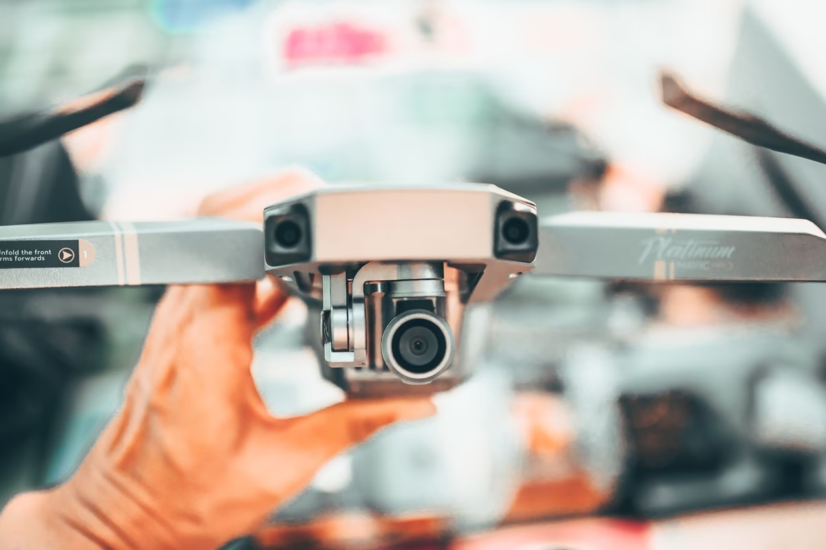
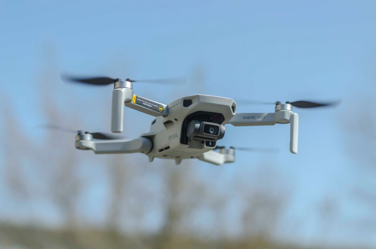
Size, Weight, Power, and Cost (SWaP-C) dictate every design decision when you're deploying thermal cores into UAV payloads, tactical scopes, or vehicle gimbals. If you're building for small unmanned aerial vehicles (sUAVs) in the field, every extra gram of payload cuts directly into flight endurance and operational range. Modern ultra-compact core designs—with footprints as tiny as 21mm × 21mm × 21mm and weights sitting under 20 grams—let integrators drop high-resolution LWIR capabilities into sub-250g drone systems without draining the flight battery in minutes.
Optical Matching, Lens Selection, and Modulation Transfer Function (MTF)
Selecting the right optics for an uncooled thermal core comes down to matching the lens's optical image circle to the physical diagonal dimensions of the microbolometer FPA. Standard glass (like N-BK7 or fused silica) blocks LWIR radiation completely. Instead, you need specialized optical materials like high-purity Germanium (Ge), Zinc Selenide (ZnSe), or chalcogenide glass engineered specifically for 8–14µm transmission.
| Focal Length (mm) | Horizontal FOV (640×512, 12µm) | Optical Aperture ($F/\#$) | Primary OEM Target Application |
|---|---|---|---|
| 5mm / 9mm | ~88° / 48° (Wide Angle) | f/1.0 - f/1.1 | Obstacle avoidance, helmet optics, close-in drone inspection |
| 13mm / 18mm / 25mm | ~33° / 24° / 17.5° (Medium) | f/1.0 - f/1.2 | Standard UAV search and rescue, perimeter surveillance, industrial plants |
| 35mm / 50mm | ~12.5° / 8.8° (Narrow) | f/1.0 - f/1.2 | Standoff perimeter defense, target ID, mid-range tactical gimbals |
| 75mm / 100mm / 150mm | ~5.8° / 4.4° / 2.9° (Ultra Narrow) | f/1.2 - f/1.4 | Long-range border security, counter-UAS platforms, coastal monitoring |
To pull maximum crispness out of your sensor, your optical assembly's Modulation Transfer Function (MTF) must align with the Nyquist spatial frequency of the microbolometer pixel array. You can calculate the Nyquist frequency ($f_N$) with this quick formula:
f_N = 1 / (2 × Pixel Pitch)
For a core with a 12µm microbolometer pitch, the Nyquist frequency sits around 41.67 line-pairs per millimeter (lp/mm). If your lens optic can't hold clean MTF contrast at that spatial frequency, fine scene details will blur together—wasting all the money you spent upgrading to a higher-resolution sensor in the first place.
Athermalization Strategies: Passive vs. Mechanical
Infrared materials—especially Germanium—have high thermo-optic coefficients ($dn/dT$). When operating temperatures shift across -40°C to +80°C out in the field, changes in refractive index combined with expansion in the mechanical lens housing lead to focus drift. In the shop, we handle camera core athermalization using two primary approaches:
- ⚙️ Passive Mechanical Athermalization: This setup combines structural barrel materials with opposing thermal expansion coefficients (like matching aluminum, stainless steel, and Delrin). As ambient temperatures shift, physical expansion in the housing mechanics actively cancels out focus shifts caused by the changing lens refractive index. It keeps focus locked without drawing a single milliamp of battery power.
- ⚙️ Active Motorized Focus Compensation: Here, an onboard stepper motor moves internal lens elements or shifts the sensor carrier board based on real-time readings from core thermistors. Active focus is practically mandatory for long telephoto optics (75mm–150mm) where thermal focus tolerances are microscopic.
3. Hardware Interfacing & Software Driver Architectures (MIPI, DVP, USB)
Plugging a high-resolution thermal core into a complete electro-optical package requires high-bandwidth, low-latency digital pipelines between the microbolometer ROIC board and your host processor (like an NVIDIA Jetson Orin, Rockchip RK3588, or Raspberry Pi single-board computer).
Physical Layer Electrical Interfaces
- ⚙️ MIPI-CSI2 (Mobile Industry Processor Interface): The gold standard serial bus for modern embedded vision systems. MIPI-CSI2 feeds low-power differential signals directly into the SoC camera serial interface, bypassing external bridge chips. This grants zero-copy memory transfers into local RAM, keeping frame latency under 10ms—essential for autonomous UAV flight control and target-tracking gimbals.
- ⚙️ DVP (Digital Video Port): A parallel bus protocol pushing clock signals, sync strobes, and 8-bit, 14-bit, or 16-bit uncompressed thermal data on every clock cycle. DVP remains widely used in custom FPGA pipelines, specialized military display drivers, and rugged embedded hardware.
- ⚙️ USB 2.0 / USB 3.0 (UVC Standard): USB Video Class compliance means driverless, plug-and-play setup across Windows, Linux, Android, and macOS hosts. By supporting UVC video endpoints alongside UVC extension units, engineers can pull live thermal streams in OpenCV, GStreamer, or FFmpeg while sending custom serial commands to tweak gain modes, NUC triggers, and color maps.
When routing high-density ribbon cables inside tight drone gimbals subjected to continuous vibration, experienced hardware engineers opt for micro-miniature board-to-board connectors built by trusted interconnect manufacturers like Amphenol to keep signals rock solid.
Linux V4L2 Subsystem Integration & Driver Architecture
Under Linux, a thermal camera core hooks into the Video4Linux2 (V4L2) driver framework. The low-level kernel driver exposes the thermal sensor as a standard device node, typically sitting at /dev/video0.
Here's how data flows through the stack: At the bottom, the uncooled LWIR core hardware connects directly over physical lines like MIPI-CSI2 or USB. The low-level driver layer handles sensor initialization, reads register settings over I2C or UART, and configures dynamic controls like manual NUC triggers or color palette shifts. Moving up into the kernel space, the V4L2 subsystem manages memory allocation using videobuf2 buffers and negotiates raw frame formats—such as 16-bit raw Y16 data or pre-processed NV12 video. Finally, at the top user space layer, applications like OpenCV, GStreamer, or custom C++ radiometric engines grab frame buffers using standard memory-mapped system calls (v4l2_ioctl and mmap), giving you real-time access to raw pixel telemetry.
If you need to configure device tree overlays, parse raw Y16 16-bit radiometric data, or write custom kernel drivers, check out our step-by-step walkthrough in the RS300 V4L2 Driver Setup and Configuration Manual.
4. Advanced Thermal Management & Onboard Edge AI ISP Processing
Uncooled microbolometers need a stable thermal environment across the sensor die to stay accurate. Even though uncooled designs drop active TEC (Thermoelectric Cooling) units to preserve battery life, localized heat spikes—caused by nearby processors, sunlight hitting the housing, or motor drive electronics—introduce thermal non-uniformity across the array. Left uncorrected, that thermal noise causes vertical striping, corner vignetting, or significant measurement drift.
Wafer-Level Packaging (WLP) and Heat Dissipation Mechanics
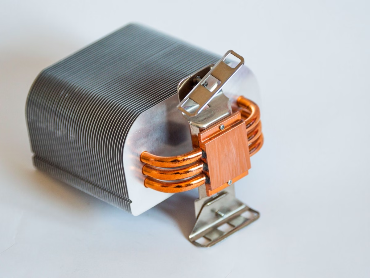
Modern miniature thermal cores utilize Wafer-Level Packaging (WLP), encapsulating the microbolometer die inside a tiny vacuum chamber right during semiconductor manufacturing. WLP cuts module size and weight dramatically while shielding the sensor from ambient convective currents. To sink operational heat away from the ROIC processing board, high-end OEM cores integrate aluminum or copper thermal cold plates. Precision thermal gap pads channel heat from high-wattage components (like FPGA processing chips or power management ICs) straight into the module's metal outer frame, allowing heat to dissipate cleanly into your system's host chassis.
Onboard AI ISP Pipeline Features
Next-generation thermal imaging modules pack onboard FPGAs or Neural Processing Unit (NPU) Image Signal Processors (ISPs) that process 14-bit or 16-bit raw sensor data right on the module before streaming video downstream. This edge processing architecture handles critical real-time image enhancements:
Key ISP Architectural Modules:
- ✅ Shutterless Adaptive Non-Uniformity Correction (NUC): Gets rid of annoying mechanical shutter clicks and frozen video frames. Algorithmic NUC monitors thermal gradients using focal plane thermistors and cleans up fixed-pattern noise (FPN) dynamically using adaptive mathematical filters.
- ✅ Dynamic Range Compression (DRC) & Adaptive Histogram Equalization: Compresses wide 14-bit raw thermal data (covering temperature ranges from -20°C to +150°C) down to clear 8-bit output without blowing out bright spots or washing out shadow detail in low-contrast environments.
- ✅ Digital Detail Enhancement (DDE): Applies high-pass spatial filtering to highlight sharp edges, thin structural wires, human targets, and vehicle shapes against noisy background clutter.
- ✅ Real-Time Radiometric Temperature Calculation: Maps digital raw pixel counts directly to absolute physical temperature readings (°C or °F) using factory calibration curves, maintaining accurate surface measurements within ±2°C or ±2%.
For a detailed breakdown of high-resolution module integration, SBC compatibility, and edge AI tracking performance, take a look at our technical deep dive on the 1280x1024 Uncooled Thermal Imaging Core for Drones & Industrial Security.
5. OEM Thermal Core Benchmark & Product Showcase
To help optical engineers, systems hardware architects, and procurement managers pick the right hardware for specific payload requirements, these two uncooled LWIR thermal core showcases highlight practical options for drone gimbals, tactical optics, industrial monitoring, and perimeter security.

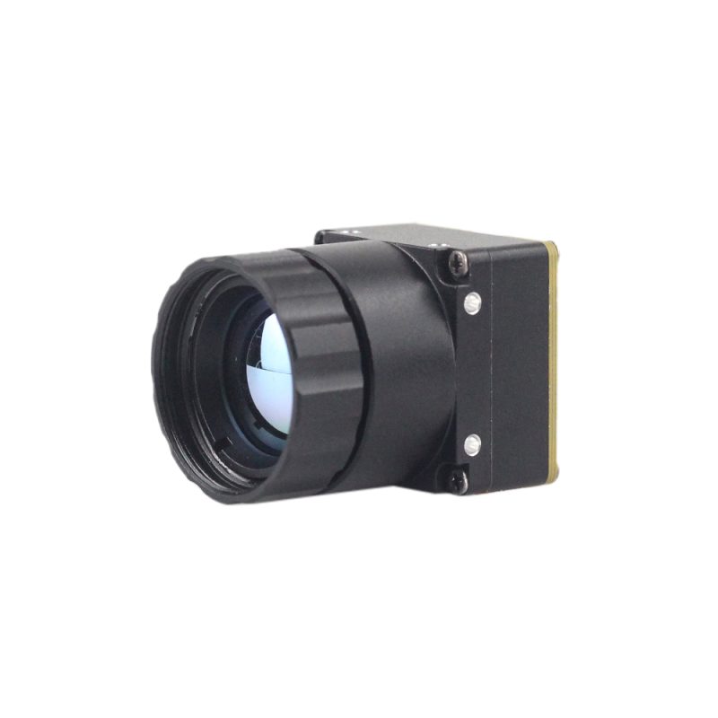
Uncooled LWIR USB Mini 640*512 Thermal Imaging Camera Core Module For Drones Similar To DJI
Designed specifically for weight-sensitive aerial gimbals, tactical handheld devices, and wearable security payloads, this ultra-miniature uncooled infrared thermal imaging module delivers crisp, sharp image presentation in an extraordinarily small footprint. Featuring a miniature housing cross-section of just 21mm × 21mm, it integrates seamlessly into sub-250g drone platforms comparable to DJI enterprise solutions.
The core offers dual resolution modes (640×512 standard or 640×480 optional) paired with flexible lens focal length options ranging from ultra-wide 5mm optics up to long-range 150mm telephoto lenses. With its high thermal stability, ultra-low power consumption, and multi-protocol output capability (USB/MIPI/DVP), it represents a cost-effective, high-performance solution for demanding OEM applications.
Technical Parameter Matrix:
| Focal Plane Resolution | 640 × 512 pixels (Optionally 640 × 480) |
| Physical Footprint | Mini-Size: 21mm × 21mm structural profile |
| Available Optical Lenses | 5mm, 9mm, 13mm, 18mm, 35mm, 50mm, 75mm, 100mm, 150mm prime lenses |
| Operational Performance | Stable non-uniformity correction, low noise, strong environmental adaptability |
| Interface Compatibility | USB Video Class (UVC), MIPI-CSI2, Digital Video Port (DVP) |
High Resolution Uncooled Infrared 1280*1024 Thermal Imaging LWIR Camera
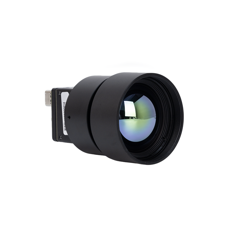
Engineered for high-end perimeter surveillance, military-grade target recognition, and ultra-precise industrial defect monitoring, this wholesale high-resolution LWIR camera core sets a new benchmark in uncooled thermal imaging performance. Featuring an expansive megapixel microbolometer focal plane array of 1280×1024 pixels, it delivers four times the spatial image details of standard 640×512 cores.
Equipped with a standard precision-engineered 25mm infrared optical lens, this unit captures fine thermal boundaries across vast spatial distances. Its advanced onboard signal processor executes high-frequency detail enhancement and thermal noise suppression, guaranteeing uncompromised target identification in zero-light, foggy, or high-smoke environments.
Technical Parameter Matrix:
| Focal Plane Resolution | 1280 × 1024 pixels (Megapixel Class High Resolution) |
| Detector Technology | Uncooled Long-Wave Infrared (LWIR) Microbolometer |
| Standard Optics Configuration | 25mm Athermalized Infrared Germanium/Chalcogenide Lens |
| Core Features | Ultra-sharp thermal sensitivity, wide dynamic range, heavy-duty industrial casing |
| Target Applications | Border monitoring, airborne ISR payloads, high-end automated industrial thermography |
Side-by-Side Comprehensive Comparison Matrix
| Specification / Core Feature | Uncooled LWIR USB Mini 640×512 Core | High Resolution Uncooled 1280×1024 Core |
|---|---|---|
| Focal Plane Array Resolution | 640 × 512 (Optional 640 × 480) | 1280 × 1024 (HD Megapixel Class) |
| Physical Module Dimensions | Ultra-Miniature: 21mm × 21mm footprint | Modular Industrial Form Factor / Chassis |
| Detector Technology | Uncooled VOx / a-Si Microbolometer | Uncooled High-Density VOx Microbolometer |
| Lens Interchangeability Options | 5 / 9 / 13 / 18 / 35 / 50 / 75 / 100 / 150 mm | 25mm Standard (Custom Focus Lens Mountable) |
| Thermal Sensitivity (NETD) | < 40mK (@ 25°C, f/1.0) | < 40mK ultra-fine temperature resolution |
| Streaming Interface Support | USB (UVC) / MIPI-CSI2 / DVP Parallel | USB / Digital Video Output / Ethernet option |
| Primary OEM Target Platform | Mini Drone Gimbals, sUAVs, Handheld Scopes | Perimeter Security, Heavy Industrial, Defense ISR |
6. Technical FAQ for Systems Engineers
Q1: Can I retrofit a higher-resolution 640×512 or 1280×1024 thermal core into an existing legacy system design?
First off, check physical clearance and mounting points inside your enclosure. Modules like our 21mm × 21mm mini 640 core are built specifically with standard footprint mounts so you can drop them into existing drone gimbals without re-machining the housing.
Second, higher resolutions crank up data throughput fast. Jumping from an old 320×240 array at 30Hz up to a 1280×1024 array at 30Hz increases raw data rate by more than sixteen times. Your carrier board interface (whether that's MIPI CSI-2 or USB 3.0) and host SoC must have enough memory bandwidth to ingest raw 14-bit pixel data without dropping frames or bogging down the video pipeline.
Finally, don't overlook your optics. Dropping to a smaller pixel pitch (like moving from 17µm to 12µm) puts strict MTF demands on your Germanium lenses at higher spatial frequencies. If your legacy lens can't deliver contrast at those spatial resolutions, blur will wipe out any detail gains you were expecting from the sensor upgrade.
Q2: What technical parameters are most critical when selecting a thermal camera core for drone gimbals and handheld tactical optics?
Thermal sensitivity (NETD under 40mK or 30mK) is what lets your operators spot targets when thermal contrast drops through the floor—think humid air, overcast skies, or dense forest cover. Better NETD ratings give automated computer vision algorithms a much cleaner signal to lock onto human or vehicle heat signatures at greater distances.
Also, frame latency must be near zero for real-time tracking and flight control. Choosing a thermal module with native MIPI-CSI2 or high-speed UVC output keeps frame transport lag under 15ms. If you need SDKs, app tools, or API references, grab technical documentation directly from our Mobile Thermal Imager Manual & Software Download Center.
Q3: How do modern uncooled thermal core modules prevent thermal drift and image noise without active shutter mechanisms?
Older systems solved this by snapping a physical shutter blade across the lens path every few minutes to re-zero pixel offset matrices—freezing live video in the process. Modern cores drop the shutter completely by running advanced shutterless Non-Uniformity Correction (NUC) algorithms inside the ISP. Precision NTC thermistors mounted right next to the microbolometer die track temperature gradients in real time.
The onboard processor feeds those thermal readings into factory-calibrated polynomial tables mapped across the module's entire operational window (-40°C to +80°C). By combining thermistor telemetry with dynamic scene analysis, the ISP continuously calculates pixel offset adjustments on the fly. This keeps image contrast high, maintains precise radiometric accuracy (typically ±2°C or ±2%), and eliminates shutter freeze entirely.
📚 References & Further Reading
- 📌 Industry Standard Interconnect Hardware: Amphenol Ruggedized Micro Interconnect Assemblies
- 📌 High-Density Sensor Flex Assemblies: KUYANG Electronic Technology Interconnect Solutions
- 📌 Linux V4L2 Driver Integration Guide: RS300 V4L2 Kernel Integration Guide
- 📌 Megapixel Thermal Core Architecture: 1280x1024 Uncooled Thermal Imaging Core Technical Review
- 📌 SDK & Software Download Center: Mobile Thermal Imager Series Manual & Software Downloads