OEM UART Thermal Camera Module: High-Resolution LWIR Cores for Drones & Robotics
2026年9月23日
12um Thermal Camera Module Guide: High-Res OEM Cores for Drones & Vision Systems
2026年9月24日
Radiometric Thermal Camera Module: OEM Integration & Raw Temperature Data Guide
Integrating non-contact thermal sensing into high-performance vision platforms requires a fundamental paradigm shift from qualitative infrared imaging to quantitative radiometric measurement. Standard uncooled Long-Wave Infrared (LWIR) camera cores output pre-processed 8-bit digital video feeds (such as YUV, RGB, or standard analog composite) intended strictly for human observation. In these qualitative systems, subtle thermal dynamics are compressed or completely distorted via aggressive dynamic range mapping, automatic gain control (AGC), and local contrast enhancement algorithms. In contrast, an OEM radiometric thermal camera module preserves the absolute physical relationship between incident infrared radiation and digitized signal output. By bypassing aesthetic image alterations, the module delivers an uncompressed, calibrated 14-bit or 16-bit linear digital data stream directly from the microbolometer focal plane array (FPA). For systems architects, robotics engineers, and embedded vision payload integrators, this linear digital array provides absolute, per-pixel surface temperature measurements across dynamic ambient conditions, unlocking automated algorithmic decision-making, predictive maintenance diagnostics, process control, and scientific thermographic analytics.
Modern industrial deployments—ranging from autonomous unmanned aerial vehicle (UAV) utility inspections and electrical substation condition monitoring to agricultural crop water stress indexing and early fire detection—demand tight thermal sensitivity, ultra-compact SWaP-C (Size, Weight, Power, and Cost) envelopes, and deterministic latency. Selecting the optimal radiometric core involves balancing optical formats, FPA resolutions (from standard 384×288 architectures up to 640×512 or higher), pixel pitches (such as modern 12μm nodes), and native physical interfaces including MIPI-CSI2, USB 2.0/3.0, and legacy analog CVBS. This comprehensive technical blueprint explores the underlying mechanics of radiometric thermal sensors, maps out low-level data extraction protocols, provides concrete hardware pinout and integration benchmarks, and evaluates high-reliability OEM cores engineered specifically for advanced system builders.
جدول المحتويات
- 👉 1. Radiometric vs. Qualitative LWIR: Architectural Distinctions
- 👉 2. Raw 14-Bit / 16-Bit Radiometric Data Pipeline & Temperature Calculation
- 👉 3. Hardware Interface Architecture: MIPI-CSI2, USB, & SWaP-C Optimization
- 👉 4. OEM Radiometric Thermal Camera Modules: Technical Specifications
- 👉 5. Embedded Edge Processing: Linux V4L2, ROS/ROS2, & Jetson Pipelines
- 👉 6. UAV Payload Design & Airborne Radiometric Calibration
- 👉 7. Deep-Dive Engineering FAQ: Radiometric Data Extraction
1. Radiometric vs. Qualitative LWIR: Architectural Distinctions
At the physical detector level, uncooled thermal imagers rely on microbolometer arrays—typically fabricated from Vanadium Oxide (VOx) or Amorphous Silicon (α-Si)—sensitive to electromagnetic radiation within the 8μm to 14μm long-wave infrared atmospheric transmission window. Infrared energy incident on each microbolometer changes the material's electrical resistance through thermal absorption. In a qualitative (observation-only) thermal core, these micro-level analog resistance fluctuations are digitized by an internal Readout Integrated Circuit (ROIC) and fed into an onboard Image Signal Processor (ISP). The qualitative ISP applies aggressive spatial and temporal algorithms such as Histogram Equalization (HEQ), Dynamic Contrast Enhancement, and digital detail enhancement (DDE).
While these image-processing techniques produce high-contrast, visually striking video feeds optimized for human visual acuity, they systematically destroy the mathematical relationship between the received optical radiance and the digital pixel value. In a qualitative feed, two pixels with identical digital values can represent drastically different physical temperatures if they reside in different local contrast neighborhoods. Conversely, identical temperatures across consecutive frames can produce divergent pixel values as the global scene shifts and the AGC algorithm dynamically rescales the display range.

إن الوحدة الحرارية الحقيقية منخفضة الاستهلاك للغاية radiometric thermal camera module preserves the absolute physical link between scene radiance and digital output. As outlined in fundamental physics and scientific documentation such as ويكيبيديا التصوير الحراري, the spectral radiance emitted by an object varies predictably with its absolute thermodynamic temperature in accordance with Planck’s Radiation Law and the Stefan-Boltzmann Law (total emissive power W = εσT4). In a radiometric core, the raw signal is preserved throughout the processing pipeline. Instead of dynamic contrast destruction, the module applies factory-calibrated linear response functions that map the analog resistance shift directly to digital numbers (DN) directly proportional to incident optical power.
To achieve industrial radiometric precision, the manufacturer subjects the camera core to comprehensive multi-point blackbody calibration across both dynamic scene temperature ranges (for example, -20°C to +150°C in high-gain mode and 0°C to +550°C in low-gain mode) and varying ambient camera core temperatures (-40°C to +80°C). The resulting calibration matrices—including per-pixel gain coefficients, dark current offsets, Non-Uniformity Correction (NUC) tables, and internal temperature sensor compensation polynomials—are permanently stored directly in the module's non-volatile EEPROM or Flash memory. When streaming data, the radiometric core outputs an uncompressed 14-bit or 16-bit linear Digital Number for every individual pixel in the detector array. This output can be transformed deterministically by the host processor into absolute temperature units (Kelvin, Celsius, or Fahrenheit) without quantization artifacts or non-linear compression.
The core distinction in system architecture between qualitative and radiometric LWIR modules governs everything from silicon layout to firmware registers:
- ⚙️ ROIC Signal Path: Qualitative cores route signals through lossy analog-to-digital auto-ranging stages. Radiometric cores maintain precision reference voltages across the microbolometer bridge to ensure consistent analog gain before wide-gamut 14-bit or 16-bit digitization.
- ⚙️ On-Die Temperature Sensors: Radiometric architectures integrate thermistors directly onto the focal plane array silicon, the optical lens barrel, and the housing enclosure to provide multi-zone telemetry for real-time drift cancellation.
- ⚙️ Deterministic ISP Pipeline: The digital signal pipeline in a radiometric engine isolates the mathematical calibration block from the display generation engine, ensuring raw radiometric arrays bypass spatial tone mapping and histogram manipulation entirely.
- ✅ Repeatability Across Operational Envelopes: Radiometric factory calibration ensures that whether an inspection occurs in sub-zero Arctic conditions or intense desert heat, a given target temperature yields an exact, calibrated digital value within rated tolerances (±2°C or ±2%).
2. Raw 14-Bit / 16-Bit Radiometric Data Pipeline & Temperature Calculation
Extracting deterministic surface temperatures from an OEM radiometric thermal camera module requires ingesting the sensor's raw digital numbers and applying the calibrated radiometry transfer function. Depending on the firmware configuration and host requirements, an OEM radiometric module generally streams data in one of two fundamental data modalities:
- ⚙️ Direct Linear Temperature Array (T-Linear Mode): The module’s internal digital signal processor computes the complete radiometric equation onboard using integrated sensor thermistors. The core streams pixel values directly proportional to absolute thermodynamic temperature, typically scaled to centi-Kelvin (0.01 K per LSB) or deci-Kelvin (0.1 K per LSB). This format significantly reduces the computational overhead of the host processor, making it ideal for microcontrollers and low-power embedded SBCs.
- ⚙️ Raw Radiometric Counts (Raw Radio-Metric Mode): The module streams uncalibrated or NUC-corrected 14-bit digital counts straight from the ROIC analog-to-digital converters along with real-time frame telemetry metadata (including focal plane array temperature, optical barrel temperature, internal housing temperature, and shutter flag status). The host CPU/GPU ingests these raw counts and applies customized Planck equations and contextual environmental corrections at the application layer.
The Radiometric Transfer Function
When processing raw 14-bit digital numbers (DN) into physical units, the system must account for total received radiance. The total energy flux reaching the detector array is a composite of object surface emission, reflected ambient background radiation, and atmospheric path transmission and emission. Mathematically, the total radiance Sالإجمالي incident on a microbolometer pixel is defined by the following radiative transfer equation:
Sالإجمالي = ε · τالجوي · L(Tالهدف) + (1 - ε) · τالجوي · L(Tbg) + (1 - τالجوي) · L(Tالجوي)
حيث:
- ⚙️ ε (Emissivity): The thermal emissivity factor of the target surface (ranging from 0.01 for polished aluminum to 0.98 for matte black paint or human skin).
- ⚙️ τالجوي (Atmospheric Transmittance): The transmission coefficient of the intervening atmosphere, dictated by distance, relative humidity, and air temperature across the 8μm to 14μm spectrum.
- ⚙️ L(Tالهدف): The blackbody spectral radiance emitted by the target object at thermodynamic temperature Tالهدف.
- ⚙️ L(Tbg): The reflected apparent background temperature originating from surrounding hot or cold structures.
- ⚙️ L(Tالجوي): The radiance emitted directly by the atmospheric path between the target and the thermal lens.
In radiometric firmware, the relationship between optical power and temperature is parameterized using an optimized form of Planck's equation:
L(T) = R / (exp(B / T) - F)
Here, R, B, and F represent sensor-specific calibration constants derived during factory blackbody characterization. When operating in direct T-Linear mode, these calculations are executed internally at frame rate (e.g., 25Hz, 30Hz, or 50Hz). For an output stream formatted in centi-Kelvin (where 1 count = 0.01 K), transforming the raw unsigned 16-bit integer (uint16) into standard engineering units is computationally trivial:
TKelvin = DN / 100.0
TCelsius = (DN / 100.0) - 273.15
For systems handling large matrix arrays, such as systems scaling beyond VGA to SXGA formats, developers can review our comprehensive analysis of high-resolution thermal imaging 1280x1024 LWIR sensor modules for OEM applications, which covers the bus bandwidth and memory buffer requirements necessary to sustain massive radiometric matrix pipelines without frame dropping.
To demonstrate high-speed temperature decoding in edge software environments, consider the following production-grade Python script utilizing NumPy for vectorized matrix operations:
import numpy as np

def process_radiometric_tlinear_frame(raw_buffer: bytes, width: int, height: int) -> np.ndarray:
    """
    Ingests a raw byte buffer from a UVC/MIPI endpoint streaming 16-bit T-Linear data
    (0.01 Kelvin per LSB) and converts it to a 2D float32 Celsius matrix.

    :param raw_buffer: Raw frame bytes (size = width * height * 2 bytes)
    :param width: Horizontal resolution (e.g., 640 or 384)
    :param height: Vertical resolution (e.g., 512 or 288)
    :return: 2D numpy array containing per-pixel temperatures in Celsius
    """
    # Cast byte stream to uint16 2D matrix
    raw_counts = np.frombuffer(raw_buffer, dtype=np.uint16).reshape((height, width))

    # Vectorized conversion: Centi-Kelvin to Celsius
    # Formula: (DN * 0.01) - 273.15
    celsius_matrix = (raw_counts.astype(np.float32) * 0.01) - 273.15

    return celsius_matrix

# Example operational usage: Extract frame stats directly in memory
# frame_celsius = process_radiometric_tlinear_frame(usb_packet_data, 640, 512)
# max_temp = np.max(frame_celsius)
# min_temp = np.min(frame_celsius)
# center_temp = frame_celsius[256, 320]
When implementing low-level drivers, embedded software engineers must manage line headers and telemetry packing. Most high-performance cores append one or two auxiliary rows of metadata directly to the image buffer. This embedded telemetry row contains mission-critical frame attributes: frame index counters, FPA core temperature readings, microbolometer bias voltages, optical shutter state flags, and current calibration slot identifiers. Applications stripping this metadata row must crop buffer heights accordingly (e.g., handling 514 lines instead of 512) to prevent memory misalignment during 2D matrix reshape operations.
3. Hardware Interface Architecture: MIPI-CSI2, USB, & SWaP-C Optimization
Integrating an OEM uncooled radiometric thermal camera module into constrained embedded architectures requires careful evaluation of electrical transport layers, physical pinout density, electromagnetic compatibility (EMC), and thermal dissipation. The choice of hardware interface directly dictates host processor CPU utilization, driver complexity, and end-system latency.
Physical Transport Protocols: MIPI vs. USB vs. CVBS
- ⚙️ MIPI-CSI2 (واجهة معالج الصناعة المتنقلة - الواجهة التسلسلية للكاميرا 2): MIPI-CSI2 represents the gold standard for integrated embedded payloads, such as drone micro-gimbals, handheld thermal scopes, and edge AI vision processors. MIPI relies on low-voltage differential signaling (D-PHY) operating across 1, 2, or 4 high-speed data lanes alongside a source-synchronous differential clock lane. It enables direct, zero-copy Direct Memory Access (DMA) into host GPU/ISP buffers (e.g., on NVIDIA Jetson, NXP i.MX8, or Rockchip SoCs). By transferring raw 14-bit or 16-bit radiometric frames straight into memory without OS driver translation overhead, MIPI ensures lowest achievable deterministic latency (typically under 10ms) and minimal CPU load. Command, control, and telemetry synchronization are handled in parallel over a dedicated 400kHz I2C or multi-megabaud UART peripheral bus.
- ⚙️ USB 2.0 / USB 3.0 (UVC + Bulk Endpoints): USB connectivity offers maximum integration convenience and cross-platform flexibility across x86 and ARM platforms. Premium radiometric modules implement a dual-endpoint architecture: a standard USB Video Class (UVC 1.1/1.5) endpoint delivering an 8-bit visual stream for real-time human display, paired with a custom high-speed USB Bulk or Vendor-Specific endpoint continuously streaming synchronized 14-bit or 16-bit radiometric matrices. This enables rapid software development using standard operating system APIs while retaining access to metric thermographic data.
- ⚙️ CVBS (فيديو مركب مع التزامن والإطفاء): Analog CVBS (providing 525-line NTSC or 625-line PAL signals over standard 75Ω coaxial traces) remains highly valued in specialized defense, security, and analog FPV drone applications. While CVBS cannot transmit digital 14-bit per-pixel temperature matrices due to its analog nature, high-performance OEM modules embed an internal on-screen display (OSD) character generator. This allows the internal DSP to superimpose real-time crosshair temperatures, multi-point spot readings, and isotherms directly onto the analog video feed.
SWaP-C Optimization and Mechanical Dissipation
Uncooled microbolometer arrays are sensitive thermal detectors. Because the bolometer sensing elements are suspended mere micrometers above a silicon readout substrate, ambient temperature shifts within the camera chassis induce localized thermal gradients across the sensor package. If not properly managed, these internal gradients degrade radiometric measurement accuracy, resulting in measurement drift and optical vignetting (thermal shading).
Engineers must ensure reliable structural heat sinking. High-performance modules feature an integrated aluminum alloy thermal reference plate on the chassis rear or base. During mechanical payload assembly, this interface plate should be coupled to the host system’s structural metal enclosure using high-performance thermal gap pads (thermal conductivity ≥ 3.0 W/m·K) or phase-change thermal interface materials. Thermal isolation from high-dissipation components—such as system-on-chip application processors, RF transmitters, or motor drivers—is essential to prevent uneven thermal radiation from striking the microbolometer housing. For multi-board interconnections in high-vibration drone environments, mission-critical systems rely on ruggedized micro-pitch board-to-board connectors engineered by interconnect leaders such as Amphenol, ensuring absolute signal integrity across high-speed differential pairs even under sustained mechanical shock.
4. OEM Radiometric Thermal Camera Modules: Technical Specifications
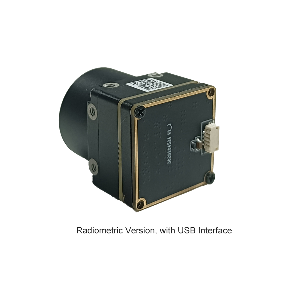
System integrators seeking compact, production-ready radiometric hardware can leverage specialized OEM cores designed for integration across robotic systems, airborne gimbals, handheld monoculars, and industrial process monitoring nodes. Below, we examine two leading industrial-grade uncooled LWIR cores from Purpleriver, engineered to address strict SWaP-C requirements without compromising radiometric stability.
وحدة كاميرا تصوير حراري مصغرة LWIR غير مبردة بدقة 640*512 مع USB للطائرات بدون طيار مشابهة لـ DJI

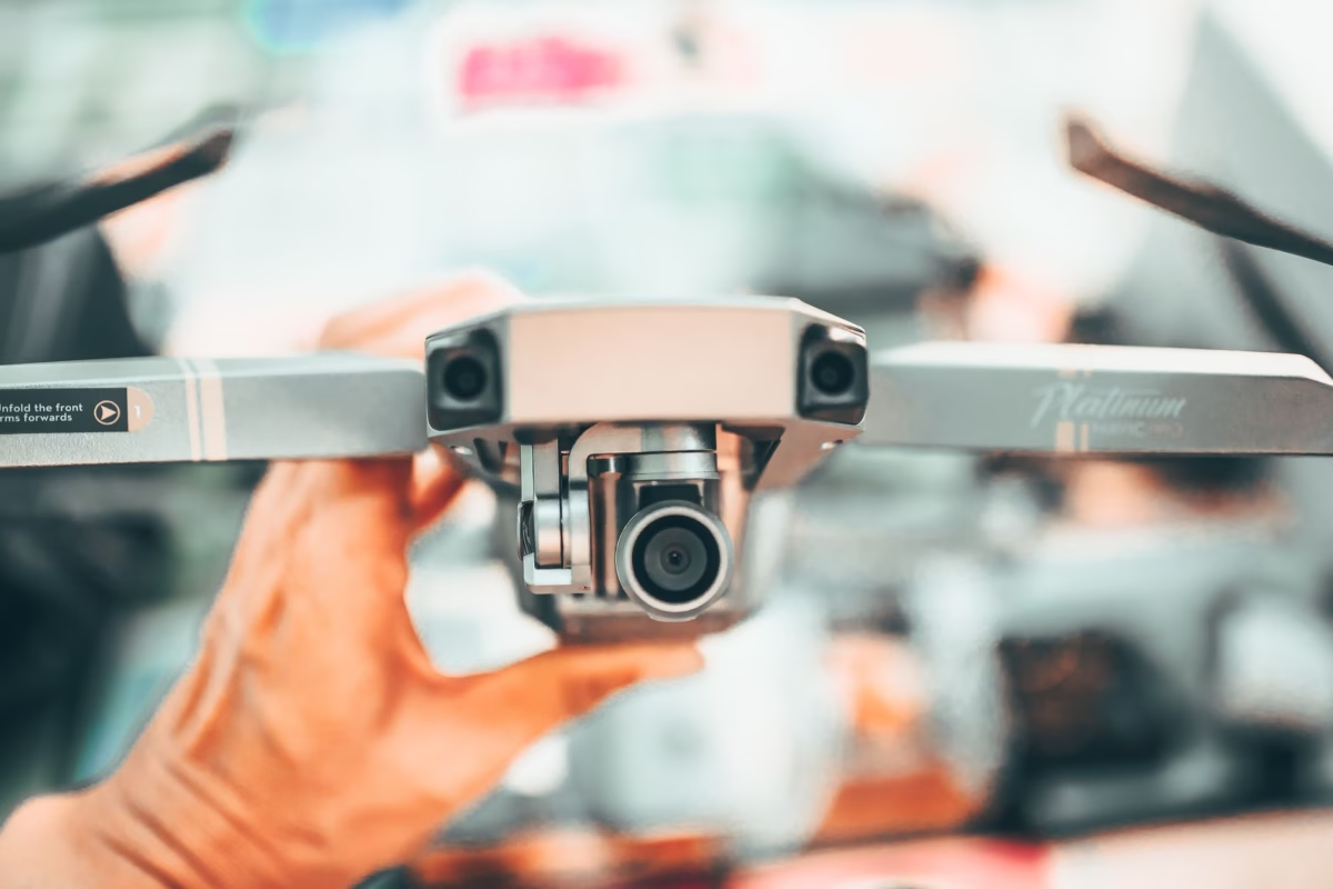
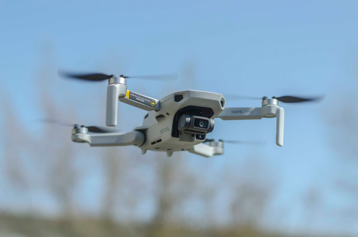
The Mini 640 uncooled infrared thermal imaging core module is an ultra-compact, high-resolution LWIR payload engine engineered specifically for micro-gimbal integration, unmanned aerial vehicles (UAVs), and portable tactical equipment. Featuring a miniature physical footprint of just 21مم × 21مم, this module delivers crisp, sharp image presentation, low latency, and low power consumption. It provides a full 640×512 resolution (with 640×480 optional) paired with a fine 12μm pixel pitch VOx sensor, offering an extensive selection of focal lengths from 5mm up to 150mm. Its native USB architecture delivers both visual preview and raw high-bit radiometric data, maintaining stable performance and strong environmental adaptability across harsh operational theatres.
- ✅ عامل الشكل: Ultra-miniature 21mm × 21mm cross-sectional envelope
- ✅ دقة FPA: 640 × 512 (اختياري 640 × 480)
- ⚙️ Optical Versatility: 5 / 9 / 13 / 18 / 35 / 50 / 75 / 100 / 150mm lens options
- ⚙️ Primary Interface: USB plug-and-play streaming raw and processed radiometric output
وحدة الكاميرا الحرارية غير المبردة MD Series بدقة 384x288 بالأشعة تحت الحمراء
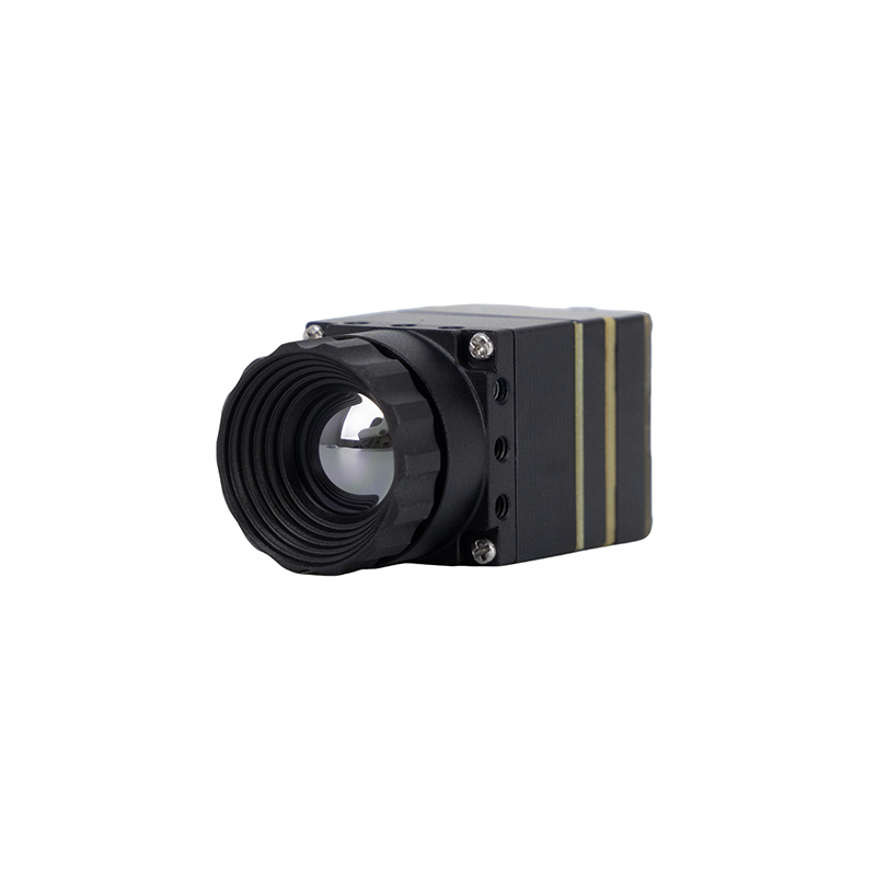
The Purpleriver MD Series thermal camera module is designed for industrial-grade precision in demanding applications including security surveillance, perimeter control, absolute temperature monitoring, and drone integration. Featuring an advanced uncooled infrared detector with a 12μm pixel pitch, it delivers outstanding thermal sensitivity and sharp, high-contrast thermal imaging. Its compact size, plug-and-play functionality, and versatile multi-interface capabilities (supporting MIPI, USB, and CVBS simultaneously) ensure rapid hardware integration into diverse host architectures. Backed by an engineering team with a Hong Kong University of Science and Technology (HKUST) background and former Huawei HiSilicon expertise, the MD Series provides complete OEM/ODM customization to meet project-specific requirements.
- ⚙️ FPA Architecture: 384 × 288 uncooled VOx microbolometer array
- ⚙️ حجم البكسل: 12 μm high-density fabrication
- ✅ Interface Redundancy: Native simultaneous support for MIPI, USB, and analog CVBS
- ✅ Engineering Pedigree: Developed by HKUST and former Huawei HiSilicon core specialists
Technical Specification Benchmark Matrix
The comparative matrix below outlines the fundamental mechanical, electrical, optical, and radiometric specifications of the Purpleriver Mini 640 and MD Series modules to assist hardware engineers with platform selection:
| Feature / Specification | Mini 640×512 LWIR USB Module | MD Series 384×288 Thermal Module |
|---|---|---|
| تقنية الكاشف | مقياس الميكروبولومتر غير المبرد بأكسيد الفاناديوم (VOx) | مقياس الميكروبولومتر غير المبرد بأكسيد الفاناديوم (VOx) |
| دقة المصفوفة | 640 × 512 بكسل (640 × 480 اختياري) | 384 × 288 بكسل |
| تباعد البكسل | 12 ميكرومتر | 12 ميكرومتر |
| النطاق الطيفي | 8 μm – 14 μm (LWIR) | 8 μm – 14 μm (LWIR) |
| Dimensions (WxHxD) | 21 مم × 21 مم (Base core profile) | Ultra-compact industrial format |
| Available Optics | 5 / 9 / 13 / 18 / 35 / 50 / 75 / 100 / 150 مم | Fixed-focus, athermalized wide & telephoto optics |
| Digital Video & Data | USB 2.0 (UVC visual stream + 14-bit radiometric stream) | Simultaneous MIPI-CSI2, USB, and Analog CVBS |
| الدقة الإشعاعية | ±2°C or ±2% (Full calibrated operating envelope) | Industrial calibrated precision across target spans |
| التطبيقات الأساسية | Drone gimbals (DJI-class payloads), thermal scopes | Industrial temperature monitoring, security, IoT edge |
5. Embedded Edge Processing: Linux V4L2, ROS/ROS2, & Jetson Pipelines
Deploying a radiometric thermal camera module on autonomous mobile robots (AMRs), industrial IoT inspection gateways, or high-performance edge compute platforms like the NVIDIA Jetson Orin Nano, AGX Orin, or Raspberry Pi CM4 requires configuring the Linux kernel video subsystem correctly. Unlike standard webcams streaming compressed 8-bit YUYV or MJPEG streams, an uncompressed 14-bit or 16-bit radiometric thermal camera communicates via uncompressed grayscale formats requiring specialized capture pipelines.
Linux Video4Linux2 (V4L2) Pipeline Configuration
Under Linux, USB and MIPI thermal cores register as standard video devices under /dev/video*. When communicating with a radiometric core configured for T-Linear or raw counts output, the core exposes specialized pixel formats. The most common four-character codes (FOURCC) used in radiometric cores are:
- ⚙️
Y16: Uncompressed 16-bit Greyscale (representing direct centi-Kelvin values or scaled linear counts). - ⚙️
Y14: 14-bit Greyscale packed within 16-bit container words. - ⚙️
GREY: 8-bit Standard Greyscale (used for qualitative previews).
Integrators can interrogate and lock the hardware driver into raw 16-bit radiometric transmission using standard command-line tools from the v4l-utils package:
# Query available hardware formats on the thermal core node
v4l2-ctl -d /dev/video0 --list-formats-ext

# Lock capture configuration to native 16-bit radiometric streaming at 640x512
v4l2-ctl -d /dev/video0 --set-fmt-video=width=640,height=512,pixelformat='Y16 '

# Verify frame rate and operational buffer parameters
v4l2-ctl -d /dev/video0 --get-fmt-video
ROS 2 (Robot Operating System) Native Integration Node
In modern autonomous robotic architectures, thermal sensor feeds must be published deterministically across the ROS 2 computational graph. Because standard RGB image pipelines cannot represent per-pixel floating-point temperature values, radiometric matrices are encapsulated in ROS 2 as sensor_msgs/msg/Image messages using the mono16 encoding. The following C++ ROS 2 node demonstrates how to capture native 16-bit radiometric frames via VideoCapture and publish them for downstream edge nodes (such as AI object detectors or SLAM fusion algorithms):
#include <rclcpp/rclcpp.hpp>
#include <sensor_msgs/msg/image.hpp>
#include <cv_bridge/cv_bridge.h>
#include <opencv2/opencv.hpp>

class RadiometricThermalPublisher : public rclcpp::Node {
public:
  RadiometricThermalPublisher() : Node("radiometric_thermal_node") {
    // Quality of Service configuration: Best effort for real-time video streaming
    rclcpp::QoS qos_profile(10);
    qos_profile.best_effort();

    publisher_ = this->create_publisher<sensor_msgs::msg::Image>(
      "thermal/radiometric_raw", qos_profile);

    // Initialize V4L2 device node in 16-bit raw mode
    cap_.open(0, cv::CAP_V4L2);
    cap_.set(cv::CAP_PROP_FOURCC, cv::VideoWriter::fourcc('Y', '1', '6', ' '));
    cap_.set(cv::CAP_PROP_FRAME_WIDTH, 640);
    cap_.set(cv::CAP_PROP_FRAME_HEIGHT, 512);
    cap_.set(cv::CAP_PROP_CONVERT_RGB, false); // Crucial: Prevent 8-bit RGB downsampling

    if (!cap_.isOpened()) {
      RCLCPP_ERROR(this->get_logger(), "Failed to open radiometric V4L2 camera core.");
      return;
    }

    // Capture loop running at 30 Hz (33.3 ms period)
    timer_ = this->create_wall_timer(
      std::chrono::milliseconds(33),
      std::bind(&RadiometricThermalPublisher::capture_and_publish, this));

    RCLCPP_INFO(this->get_logger(), "Radiometric 16-bit node initialized successfully.");
  }

private:
  void capture_and_publish() {
    cv::Mat frame;
    if (cap_.read(frame)) {
      // frame.type() is CV_16UC1 containing raw centi-Kelvin or digital counts
      std_msgs::msg::Header header;
      header.stamp = this->now();
      header.frame_id = "thermal_optical_frame";

      // Bridge OpenCV 16UC1 matrix directly to ROS sensor_msgs/Image
      sensor_msgs::msg::Image::SharedPtr msg =
        cv_bridge::CvImage(header, "mono16", frame).toImageMsg();

      publisher_->publish(*msg);
    } else {
      RCLCPP_WARN_THROTTLE(this->get_logger(), *this->get_clock(), 1000,
                           "Frame drop detected on radiometric capture bus.");
    }
  }

  cv::VideoCapture cap_;
  rclcpp::Publisher<sensor_msgs::msg::Image>::SharedPtr publisher_;
  rclcpp::TimerBase::SharedPtr timer_;
};

int main(int argc, char** argv) {
  rclcpp::init(argc, argv);
  rclcpp::spin(std::make_shared<RadiometricThermalPublisher>());
  rclcpp::shutdown();
  return 0;
}
When deploying this node on NVIDIA Jetson architectures, zero-copy buffer sharing through NVMM (NVIDIA Memory Management) can be leveraged to feed the 16-bit arrays directly into TensorRT inference engines. For example, edge AI models performing crack detection or thermal anomaly localization can process float32 converted matrices directly in GPU memory, avoiding CPU memory copies and maintaining 60 FPS processing throughput.
6. UAV Payload Design & Airborne Radiometric Calibration
Deploying a radiometric thermal camera module aboard small unmanned aerial systems (sUAS) introduces complex thermodynamic and aerodynamic phenomena that can compromise measurement accuracy if not properly addressed during mechanical payload design.
Managing Rotor Downwash and Convective Cooling
Multi-rotor drones generate high-velocity, turbulent airflow that impinges directly upon the gimbal payload. If the external optical assembly is exposed to uneven convective downwash, localized cooling occurs across the front Germanium lens element. Germanium has a very high index of refraction (approximately 4.0), and rapid temperature drops across its surface introduce thermal gradients between the center of the lens and its metal retaining ring. This physical phenomenon introduces radial vignetting (sometimes referred to as the "halo effect"), causing per-pixel temperature readings at the periphery of the image to read several degrees lower than identical targets at the center of the frame.
To eliminate convective cooling artifacts, system designers should integrate the radiometric core within an aerodynamically sealed payload housing. Utilizing an anti-reflective (AR) coated protective Germanium or Chalcogenide window seated flush with the outer gimbal enclosure isolates the imaging lens from turbulent airflows. Additionally, modules like the Purpleriver Mini 640 incorporate internal thermal sensor arrays that monitor lens barrel temperatures in real time, allowing internal firmware algorithms to dynamically correct for temperature-induced lens emission changes.
Non-Uniformity Correction (NUC) Shutter Coordination
Uncooled microbolometers exhibit inherent temporal drift caused by ambient temperature shifts and internal electronics heating. To maintain spatial uniformity and absolute accuracy, the core must periodically perform a Non-Uniformity Correction (NUC), also termed Flat Field Correction (FFC). During an FFC cycle, an internal mechanical solenoid moves an athermal shutter blade into the optical path for 200ms to 400ms. The core measures this uniform temperature reference and recalculates per-pixel offset vectors.
In high-speed aerial inspections (such as scanning miles of high-voltage transmission lines or solar farm arrays), an unannounced NUC calibration freezes the video feed and halts data streaming. This brief interruption can cause autonomous tracking loops to drop locks or result in missed imagery at critical flight waypoints. OEM modules like the Mini 640 and MD Series mitigate this operational challenge through software-controllable NUC management. The flight computer can inhibit automated shutter activations over serial UART or USB commands during active inspection runs, and instead trigger shutter calibrations programmatically when the UAV transitions between waypoints or executes turns.
Optics, Weight, and Flight Endurance
Flight endurance on small drones scales inversely with total payload mass. The transition from legacy 17μm pixel pitch sensors to modern 12μm microbolometer arrays (as featured on the Mini 640 and MD Series) yields significant physical advantages. Because the individual detector elements are smaller, a 12μm sensor requires a shorter focal length lens to achieve the identical optical Field of View (FOV) and Instantaneous Field of View (IFOV) compared to a 17μm sensor. Shorter focal length lenses use smaller Germanium optical elements, drastically reducing overall payload mass, reducing the required gimbal motor torque, and directly extending overall flight endurance.
7. Deep-Dive Engineering FAQ: Radiometric Data Extraction
Can I extract per-pixel raw temperature matrix data and export it to CSV or custom software?
Is the radiometric module controllable across different programming languages and embedded systems?
What makes this module ideal for compact drone payloads and DIY scopes compared to standard cores?
📚 المراجع والقراءات الإضافية
- 🔹 المعيار الصناعي: Physical principles of infrared thermography and radiometric equations referenced via ويكيبيديا التصوير الحراري.
- 🔹 Interconnect Reliability: Industrial board-to-board high-speed interconnect standards documented by Amphenol Industrial Interconnect Systems.
- 🔹 Related High-Resolution Guide: Deep architectural analysis of large-format sensors via High-Resolution Thermal Imaging 1280x1024 LWIR Sensor Modules for OEM Applications.
- 🔹 Regional Mobile & Modular Guides: Detailed technical guides on compact thermal integration available at our Russian Technical Engineering Portal و Polish Industrial Knowledge Base.