Top IR Camera Module Solutions for Drones & Embedded AI: OEM Integration Guide
2026年7月31日
High-Performance Thermal Micro Camera Module for Drones & Embedded AI Systems
2026年8月3日
Next-Gen LWIR Thermal Module Guide: OEM Integration for Drones & AI Vision
Look, if you are building unmanned aerial vehicles (UAVs), autonomous mobile robots, or edge AI vision systems today, you already know that long-wave infrared (LWIR) sensing is no longer an exorbitant defense-only luxury. It has become an absolute necessity for commercial and industrial OEMs. Operating right inside the 8–14 µm spectral window, modern LWIR thermal camera modules detect ambient infrared radiation emitted directly by a target's physical structure—no external illuminator required. That means your vision system can slice right through heavy smoke, atmospheric haze, fog, and total darkness. But here is the catch: dropping a thermal core into a tiny drone gimbal, a handheld diagnostic tool, or a high-throughput edge processor is not plug-and-play. You have to balance tough engineering trade-offs between optical resolution, pixel pitch, thermal dissipation, radiometric calibration, and high-bandwidth digital bus selection.
This technical blueprint is written for hardware architects, optical engineers, and computer vision devs tasked with embedding OEM LWIR thermal camera cores into real-world products. From assessing uncooled Vanadium Oxide (VOx) microbolometer arrays against legacy MWIR systems to squeezing out low-latency SWaP (Size, Weight, and Power) gains, this guide breaks down the underlying physics, digital interface protocols, mathematical routines, and hardware benchmarks you need to take a prototype off the bench and push it into volume production.
Table of Contents
- 👉 1. Physics of LWIR Thermal Sensing vs. MWIR/SWIR
- 👉 2. SWaP-C Engineering for Airborne & Edge Platforms
- 👉 3. Interface Protocols, Digital Outputs & SDK Workflows
- 👉 4. Radiometric Calibration & Edge AI Target Recognition
- 👉 5. OEM Module Benchmark & Technical Specifications
- 👉 6. Technical Deep-Dive FAQ
1. Physics of LWIR Thermal Sensing vs. MWIR/SWIR
To pick the right sensor for an autonomous vision platform, you have to start with the physics. Thermal radiation is governed by Planck’s Law of Blackbody Radiation and Wien’s Displacement Law. Wien's law tells us that the peak emission wavelength of a blackbody is inversely proportional to its absolute temperature ($T$). For ambient targets sitting around room or Earth outdoor temperatures (~300 K / 27°C), peak thermal emittance lands dead center in the Long-Wave Infrared (LWIR) band between 8 µm and 14 µm.
When picking spectral bands for automated vision payloads, here is how LWIR stacks up against Short-Wave Infrared (SWIR) and Mid-Wave Infrared (MWIR):
| Parameter | SWIR (0.9 – 1.7 µm) | MWIR (3.0 – 5.0 µm) | LWIR (8.0 – 14.0 µm) |
|---|---|---|---|
| Primary Source | Reflected photons (Solar / IR LED) | High-temp thermal emissions (>500 K) | Ambient temperature emissions (~300 K) |
| Cooling Requirement | Uncooled (InGaAs) / TEC | Cryogenic Stirling Cooler (~77 K) | Uncooled Microbolometer (VOx / a-Si) |
| Power Consumption | Low (1.0 W - 2.5 W) | High (5.0 W - 15.0 W+) | Ultra-Low (0.7 W - 1.2 W) |
| System MTBF | > 50,000 Hours | ~3,000 – 8,000 Hours (Cooler limited) | > 50,000 Hours |
| Obscurant Penetration | Moderate (Light Haze) | Good (High-humidity maritime) | Superior (Dense Smoke, Dust, Fog) |
For commercial UAV designers, industrial inspection crews, and mobile robotics engineers, uncooled LWIR Focal Plane Arrays (FPAs)—typically constructed using Vanadium Oxide (VOx) or Amorphous Silicon (a-Si) microbolometer structures—offer serious structural advantages over alternative bands:
- ✅ No Cryogenic Coolers Required: Uncooled LWIR microbolometers work by letting incoming thermal energy physically heat up suspended bridge structures on the die, changing their electrical resistance. Because you don't need a mechanical Stirling cryocooler, system reliability skyrockets. Your operational MTBF jumps past 50,000 continuous hours, while eliminating mechanical motor vibration and cooling noise.
- ✅ Punctuates Particle Scattering: Mie scattering ruins visible and SWIR image channels when airborne dust or smoke particles match short light wavelengths. Operating within the 8–14 µm window keeps scattering losses minimal, letting you image clearly through thick forest fire smoke, industrial dust storms, and heavy coastal fog.
- ✅ True Zero-Light Passive Imaging: SWIR and visible cameras need active illuminators (like 850nm or 940nm LED floodlights) under pitch-black conditions. That drains extra battery power and signals your position to everyone in range. LWIR camera cores rely solely on self-emitted thermal photons, performing identically whether it is high noon or midnight.
When designing high-reliability custom PCBs for thermal processing, hardware teams frequently bridge raw microbolometer outputs using dedicated video interface chips—like those manufactured by JM Chip—to manage pixel clock formatting, parallel-to-serial conversion, and deserialization before handing off raw digital frames to host SoC application processors.
2. SWaP-C Engineering for Airborne & Edge Platforms
In aerospace payload design and field robotics, Size, Weight, Power, and Cost (SWaP-C) dictate engineering success. Every extra gram of weight or milliwatt of parasitic thermal load cuts directly into flight times or battery endurance.
Critical SWaP-C Integration Dimensions
Here's the deal: shrinking sensor pixel pitch from 17 µm down to 12 µm cuts the required optical aperture diameter by roughly 30% for any given focal length and FOV. That translates directly to geometric volume savings in raw optical glass (Germanium or Chalcogenide), enabling full-featured 640×512 LWIR cores to pack into ultra-miniature 21mm × 21mm footprints.
Key Hardware Optimization Pillars:
- ⚙️ Miniaturized Mechanical Form Factors: Modern uncooled LWIR cores feature ultra-compact mechanical footprints down to 21mm × 21mm. Shrinking core volume makes it significantly easier to balance payload weights inside tiny 3-axis brushless gimbals. Less mass means smaller motor torque requirements, lower power consumption, and cleaner stabilization during fast flight turns.
- 🌡️ Thermal Drift & Passive Heat Dissipation: Microbolometer arrays react to ambient temperature changes. If surrounding processing chips heat up the camera housing unevenly, you will see non-uniformity drift and gain errors creep into your imagery. To prevent this, design solid conductive heat paths using the chassis or drone frame as a heat sink, keeping the array in thermal equilibrium without needing noisy, power-hungry fans.
- 🔬 Pixel Pitch Compression & Lens Selection: Moving from legacy 17 µm detectors to 12 µm arrays allows smaller optical clear apertures while retaining identical spatial resolution. Fast lenses made from Chalcogenide glass or Germanium maintain high optical throughput (f/1.0 to f/1.2) without adding dead weight. Lens selection—ranging from wide 5mm primes for short-range obstacle avoidance to long telephoto 150mm optics—directly dictates your Detection, Recognition, and Identification (DRI) ranges.
For specialized vehicular equipment builds—like night-vision automotive systems—space constraints and ambient temperature stability are tough engineering constraints. If you want to dive deeper into custom vehicular mounting setups, take a look at our practical guide on engineering a thermal imaging car camera.
3. Interface Protocols, Digital Outputs & SDK Workflows
To process thermal frames at real-time speeds, hardware developers must pick digital transport standards that transfer full pixel bit-depth without inducing latency or stressing host CPU cycles. Old analog formats like CVBS (NTSC/PAL) degrade signal clarity, add conversion noise, and strip away pixel temperature values, making them non-viable for automated computer vision architectures.
Digital Transport Protocol Matrix
| Interface Standard | Data Bandwidth | Integration Overhead | Best Suited Architecture |
|---|---|---|---|
| USB 2.0 / 3.0 (UVC Standard) | 480 Mbps / 5 Gbps | Plug-and-play OS drivers (Linux, Win, Android) | Rapid prototyping, edge PCs, smart devices |
| MIPI-CSI2 / LVDS | Up to 2.5 Gbps / lane | Low-level V4L2 kernel driver development | Embedded SoCs (NVIDIA Jetson, Rockchip) |
| DVP Parallel (BT.656/1120) | Direct Pixel Clock Sync | FPGA / MCU GPIO state machine logic | Custom ASIC pipelines, ultra-low latency hardware |
Look, an entry-level microcontroller like an Arduino works fine for reading single-point thermopile sensors over I2C, but pulling full 256×192 or 640×512 thermal matrices at high frame rates (25Hz/50Hz) demands a 32-bit Linux host processor running dedicated hardware image pipelines.
SDK & Processing Pipeline Workflow
An SDK pipeline takes uncorrected raw detector signals and transforms them into clear thermal video streams alongside true radiometric matrices through five distinct stages:
- ⚙️ 1. Raw Data Ingestion (14-Bit Y14 Output): The initial digital value ($S$) generated by each pixel corresponds to microbolometer element resistance before calibration adjustments. Modern camera modules stream uncompressed 14-bit raw datasets directly via MIPI or USB UVC pipes.
- ⚙️ 2. Non-Uniformity Correction (NUC): Due to tiny silicon manufacturing variations across microbolometer elements, raw responses differ slightly per pixel. Internal onboard routines apply one-point or two-point NUC corrections—frequently dropping an internal mechanical shutter for reference—to equalize array response across a uniform field.
- ⚙️ 3. Adaptive Dynamic Range Control & AGC: High dynamic range scenes (spanning -20°C to +150°C) require contrast stretching. The SDK applies histogram equalization and plateau algorithms to map 14-bit data down into high-contrast 8-bit images without washing out critical thermal boundaries.
- ⚙️ 4. Digital Detail Enhancement (DDE): High-pass spatial filters separate high-frequency structural lines from low-frequency thermal backgrounds. DDE brings out subtle edges, thin structural wires, and fine fractures for both human operators and automated AI models.
- ⚙️ 5. Radiometric Matrix Demuxing: In parallel, raw pixel values pass through internal calibration lookup tables stored on onboard EEPROM, producing real-time target surface temperature arrays (°C/°F) for automated processing.
If you are building lightweight, portable diagnostic gear that pairs LWIR camera modules directly with mobile hardware, check out our walkthrough on deploying a mobile radiometric thermal camera.
4. Radiometric Calibration & Edge AI Target Recognition
The true power of advanced LWIR modules lies in radiometry—measuring absolute per-pixel target surface temperatures across the entire scene matrix in real time.
The Radiometric Measurement Equation
To convert raw digital readings ($S_{total}$) into an accurate target surface temperature ($T_{obj}$), the host application calculates a balance equation that accounts for target emissivity ($\varepsilon$), atmospheric transmittance ($\tau$), reflected background radiation ($T_{refl}$), and ambient atmospheric temperature ($T_{atm}$):
Stotal = ε · τ · S(Tobj) + (1 - ε) · τ · S(Trefl) + (1 - τ) · S(Tatm)
By inputting target emissivity (e.g., concrete $\varepsilon \approx 0.95$, oxidized metal $\varepsilon \approx 0.80$) along with distance estimates, host algorithms solve for $S(T_{obj})$ and reference factory lookup tables to calculate real-time surface temperatures across all pixels.
Edge AI Thermal-Optical Sensor Fusion
Pairing radiometric LWIR thermal modules with Edge AI hardware accelerators (such as NVIDIA Jetson TensorRT, Rockchip NPU engines, or ONNX hardware runtimes) unlocks high-reliability automated target detection:
- 🎯 Multi-Spectral Affine Homography: Aligning 4K visible RGB frames with lower-resolution 640×512 thermal matrices using spatial homography creates a unified multi-spectral tensor array for your AI model.
- 🎯 Deep Learning Object Detection (YOLO / MobileNet): Thermal imagery instantly flags human, animal, or engine heat signatures against cold background scenery. Dual-stream AI models accurately detect and classify targets even when visual camera channels are completely blinded by glare, smoke, or darkness.
- 🎯 Predictive Fault & Structural Monitoring: Edge AI models continuously track scene temperature distributions. Localized heat spikes trigger immediate automated alarms long before component failures occur. For example, non-destructive testing utilizes thermal imagery to reveal hidden internal voids in concrete and steel structures. To see how this works in practice, read our technical paper on structural defect inspection via thermal imaging.
5. OEM Module Benchmark & Technical Specifications
Here is a detailed comparison of production-ready OEM LWIR thermal camera modules engineered for drone payloads, mine detection gear, search-and-rescue systems, and handheld tools.
Uncooled LWIR Mini 256*192 Thermal Imaging Camera Module
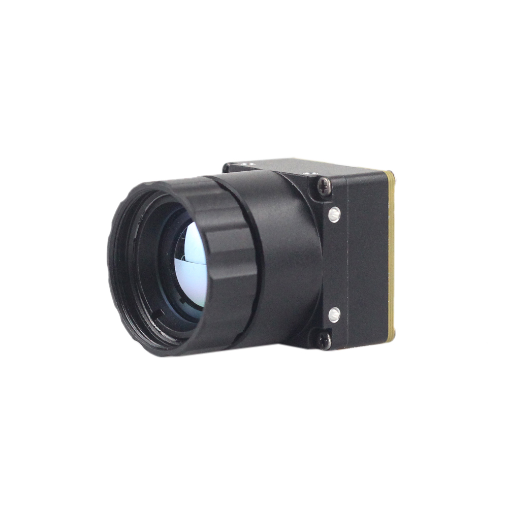
The Mini 256 Uncooled LWIR Thermal Camera Module is built around a sensitive infrared focal plane array, engineered to deliver crisp thermal video and reliable radiometric measurements. Designed specifically for ultra-compact systems, it captures incoming long-wave thermal radiation and streams clear, uniform radiometric datasets for real-time edge processing.
- ⚙️ Resolution: 256 × 192 pixel array layout
- ⚙️ Detector Technology: High-sensitivity uncooled VOx / a-Si microbolometer
- ⚙️ Spectral Range: 8 µm to 14 µm (LWIR)
- ⚙️ Thermal Radiometry: Onboard per-pixel temperature calibration for target analysis
- ✅ Primary Applications: Subterranean mine and UXO detection, micro drone payloads, portable handheld inspection tools, and close-range machine vision systems
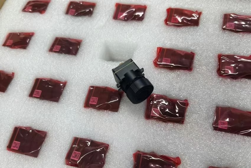
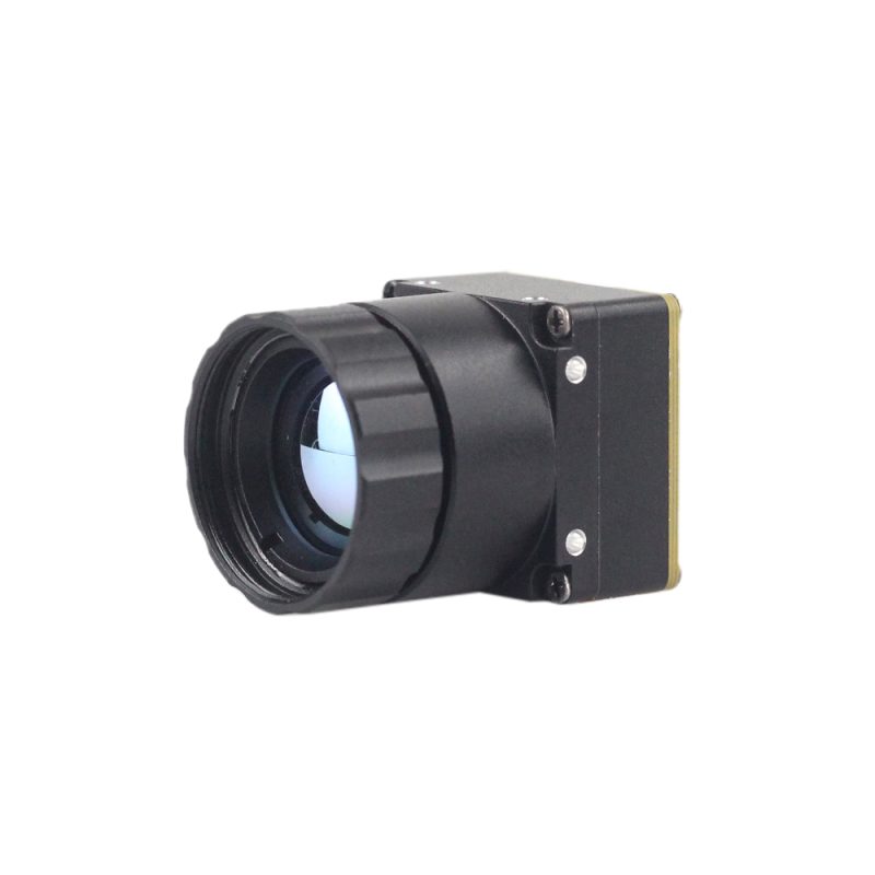
Uncooled LWIR USB Mini 640*512 Thermal Imaging Camera Core Module

Engineered for drone gimbals, advanced robotics, and thermal night-vision gear, the Mini 640 Uncooled LWIR USB Camera Core Module offers high thermal resolution inside an extraordinarily tiny package. Featuring an ultra-small 21mm × 21mm housing profile, it delivers high image clarity, low power consumption, and solid thermal stability in harsh outdoor environments.
- ⚙️ Resolution Options: High-density 640 × 512 array (640 × 480 configuration optional)
- ⚙️ Physical Profile: Miniaturized 21mm × 21mm chassis
- ⚙️ Optical Lenses: 5mm, 9mm, 13mm, 18mm, 35mm, 50mm, 75mm, 100mm, and 150mm prime optical lens options
- ⚙️ Digital Output: Driverless USB output (UVC compliant) for plug-and-play cross-platform OS integration
- ✅ Environmental Protection: Built to withstand severe operating temperature swings without thermal drift
Comparative OEM Module Technical Benchmark Table
| Technical Feature | Mini 256 Uncooled Module | Mini 640 USB Core Module |
|---|---|---|
| Focal Plane Array Resolution | 256 × 192 (49,152 active pixels) | 640 × 512 / 640 × 480 (327,680 pixels) |
| Mechanical Housing Dimensions | Ultra-compact OEM mini shell | Sub-miniature 21mm × 21mm profile |
| Supported Focal Lengths | Fixed short/medium range prime optics | 5mm up to 150mm prime optical lenses |
| Output Data Interface | Raw digital parallel / serial bus | Direct USB (UVC class driverless connection) |
| Radiometric Precision Output | Uniform calibrated radiometry | Calibrated digital thermal temperature stream |
| Primary Target Platform | Mine detection, sUAS, short-range tools | High-altitude sUAS, long-range tracking, AI edge vision |
6. Technical Deep-Dive FAQ
Why choose an Uncooled LWIR Thermal Module over MWIR for drone and industrial applications?
Choosing an uncooled LWIR thermal module over a cooled Mid-Wave Infrared (MWIR) core comes down to clear practical realities: Size, Weight, Power, Cost (SWaP-C), and maintenance longevity. Cooled MWIR systems rely on internal cryogenic Stirling coolers to chill their focal plane arrays down to roughly 77 Kelvin (-196°C). That extra hardware gives extreme sensitivity for long-range military target acquisition, but it imposes severe physical penalties: system mass increases significantly, power consumption skyrockets to 5–15 Watts, start-up times take 3 to 10 minutes while waiting for cooldown, and the mechanical cooler limits operating lifespan to just 3,000 to 8,000 hours before mechanical service is needed.
Uncooled LWIR microbolometer modules operate directly at ambient room temperatures with zero mechanical cooling parts. Modern Vanadium Oxide (VOx) arrays deliver low noise floor figures (NETD < 40–50 mK), making them effective for industrial thermography, power line inspection, search-and-rescue, and commercial UAV operations. Removing the cryocooler drops power draw down to around 1 Watt, shrinks the physical footprint to sub-miniature 21mm × 21mm dimensions, and provides instantaneous boot-up performance. Operating MTBF scales past 50,000 hours, keeping long-term maintenance costs near zero for commercial autonomous fleets.
How do I select the right resolution (e.g., 256x192 vs. 640x512) for mini thermal modules?
Selecting between a 256×192 array and a higher-resolution 640×512 LWIR module depends directly on target range, onboard compute capacity, and field-of-view (FOV) requirements. Sensor resolution dictates spatial resolution—the number of pixels placed on target at a specific distance—governing Johnson’s Criteria performance for Detection, Recognition, and Identification (DRI).
A 256×192 array offers 49,152 active pixels, making it ideal for short-to-medium range tasks (typically 0 to 50 meters). Applications include close-range mine and UXO detection, handheld thermal meters, HVAC diagnostics, and obstacle avoidance on mobile ground robots. The lower data rate keeps digital transport simple and reduces host processor workloads, fitting easily into power-constrained embedded builds.
A 640×512 resolution core provides 327,680 active pixels—over 6.6 times the spatial density of a 256×192 matrix. Paired with tight 12 µm pixel pitches, a 640×512 module covers wide fields of view without sacrificing critical spatial angular detail. Drones operating at higher altitudes (60 to 120+ meters AGL) rely on 640×512 arrays to survey power grids, solar farms, or agricultural fields while keeping enough pixels-on-target for real-time automated AI classification.
Can these LWIR modules support real-time Edge AI thermal detection?
Yes, modern OEM LWIR thermal camera modules are designed for integration with edge AI hardware platforms. Unlike legacy camera cores that only output pre-processed, analog video streams, modern digital LWIR modules deliver raw uncompressed 14-bit frames or digital video over low-latency protocols, including MIPI-CSI2, USB 3.0 UVC, and DVP parallel interfaces.
These high-speed interfaces connect straight to embedded AI accelerators—such as NVIDIA Jetson modules, Rockchip RK3588 processors, or custom FPGA/NPU architectures—without introducing frame delay or compression artifacts. Computer vision engineers can push 14-bit or AGC-stretched thermal frames directly into deep learning models (such as TensorRT-accelerated YOLO pipelines) at full frame rates (25Hz/50Hz). This enables real-time autonomous target detection in total darkness, automated radiometric temperature threshold detection for industrial facility monitoring, and multi-spectral sensor fusion with visual RGB cameras in demanding environments.
📚 References & Further Reading
- Industry Standard: Silicon & Signal Processing Interfacing: JM Chip
- Industry Standard: Microcontroller Prototyping Platform: Arduino
- Related Guide: Automotive Integration: Building a Thermal Imaging Car Camera
- Related Product: Smart Device Integration: Mobile Radiometric Thermal Camera Module
- Related Application: Civil Infrastructure Inspection: Subsurface Defect Inspection via Thermal Imaging