Choosing the Best Thermal Imager: Industrial AI Modules vs. Budget Tools
2026年8月5日
AI Thermal Camera Selection Guide: High-Precision Modules & OEM Integration
2026年8月6日
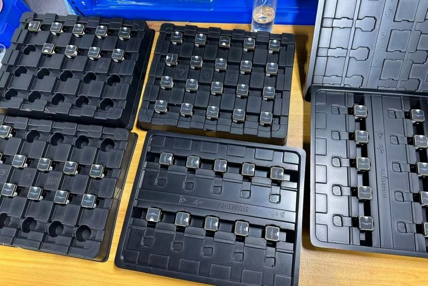
Commercial Infrared Imager Modules: High-Res AI Thermal Guide for Engineers
Look, if you are building autonomous systems, mobile robotics, or long-range perimeter security networks today, picking the right infrared imager core is usually where the real engineering headaches begin. We are long past the days when thermal imaging meant slapping together a slow, clunky diagnostic camera with a 9Hz refresh rate. Modern long-wave infrared (LWIR) OEM camera cores rely on tight hardware integrations: custom Application-Specific Integrated Circuits (ASICs), Vanadium Oxide (VOx) microbolometer focal plane arrays (FPAs), and hardware-accelerated Edge AI running right at the sensor level. Whether you are retrofitting multi-rotor UAVs for low-light reconnaissance or embedding machine vision into an automated industrial monitoring line, you have to balance brutal trade-offs across spatial resolution, thermal sensitivity (NETD), interface bandwidth, and Size, Weight, Power, and Cost (SWaP-C).
Here's the deal: this guide cuts through the supplier datasheets and marketing fluff. We will walk step-by-step through operational waveband physics, optical design realities, digital bus selections (like MIPI CSI-2, RJ45 RTSP/IP, and CVBS), and real-world system integration strategies. Consider this document your practical engineering blueprint for integrating commercial thermal camera modules into mission-critical hardware stacks.
Table of Contents
- 👉 1. Executive Summary & Introduction
- 👉 2. Fundamentals of Thermal Infrared Imaging Physics
- 👉 3. Sensor Resolution, Pixel Pitch, and Spatial Recognition
- 👉 4. Embedded Video Interfaces: MIPI, RJ45/RTSP, and CVBS
- 👉 5. ASIC Processing, Edge AI Acceleration, and Palette Generation
- 👉 6. Commercial OEM Infrared Imager Specifications
- 👉 7. SWaP-C Optimization for Drones and Autonomous Platforms
- 👉 8. Deep-Dive Frequently Asked Questions (FAQ)
2. Fundamentals of Thermal Infrared Imaging Physics
When you work with an infrared imager in the Long-Wave Infrared (LWIR) spectrum (8 μm to 14 μm), you aren't looking at reflected visible light. You are reading raw heat signatures directly emitted by the scene. Near-Infrared (NIR) and Short-Wave Infrared (SWIR) sensors still need ambient photons or active IR floodlights to hit a target and bounce back. LWIR uncooled sensors operate purely on Planck’s Law of Blackbody Radiation, capturing micro-Kelvin thermal emissions and turning them into digital temperature maps.
Let's follow the signal path inside the camera core. Passive LWIR radiation enters through custom antireflective-coated Germanium (Ge) lenses. Standard optical glass blocks LWIR completely; Germanium, however, acts as a near-transparent window between 8 μm and 14 μm while completely shutting out visible wavelengths. The focused thermal image hits an uncooled microbolometer Focal Plane Array (FPA). Each pixel on that array is a tiny micromachined thermistor—often made from thin-film Vanadium Oxide (VOx) or Amorphous Silicon (a-Si)—suspended over a silicon substrate by micro-legs. Incoming thermal radiation warms these suspended bridges, causing a measurable drop in electrical resistance. An integrated Readout Integrated Circuit (ROIC) reads those resistance shifts row by row, passing the analog voltage to a high-precision analog-to-digital converter (ADC) that converts the signal into raw 14-bit digital counts.
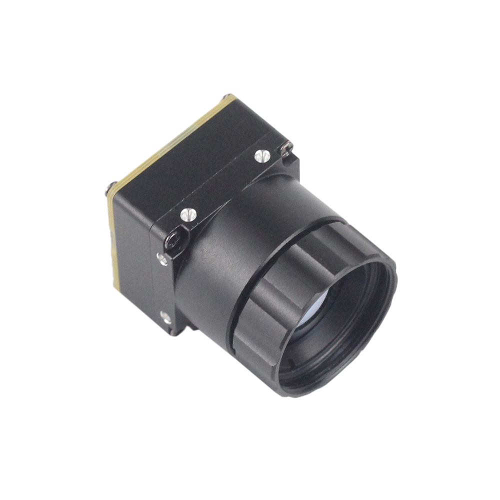
In the shop, when we evaluate uncooled LWIR camera cores, three technical metrics dictate true real-world performance:
- 🧪 Noise Equivalent Temperature Difference (NETD): Rated in millikelvins (mK), NETD tells you the absolute smallest temperature differential the sensor can pick out above its own internal thermal noise floor. Standard core specs run around ≤50mK, but high-performance cores hit ≤30mK (@ f/1.0, 300K). Lower NETD means cleaner target boundaries, vastly improved signal-to-noise ratio (SNR), and crisp contrast even during high-humidity or low-contrast thermal environments.
- ⏱️ Thermal Time Constant: This is the speed at which a microbolometer pixel membrane heats up or cools down when exposure changes, usually sitting between 8ms and 12ms. A lower time constant prevents thermal trailing, image ghosting, and blur when tracking fast targets from a moving UAV or high-speed autonomous ground vehicle.
- 🔧 Non-Uniformity Correction (NUC): Because microbolometer pixels suffer individual semiconductor variations and drift over ambient thermal fluctuations, camera cores use Non-Uniformity Correction. This is done either by firing a mechanical shutter flag briefly to grab a flat-field reference or by running advanced shutterless algorithmic NUC to continuously equalize pixel gains across the FPA.
If you are actively prototyping embedded vision systems, explore our thermal engineering knowledge base for deeper signal path analysis, or pick up rapid-prototyping breakout boards from places like DFRobot during initial bench tests.
3. Sensor Resolution, Pixel Pitch, and Spatial Recognition
Selecting array resolution isn't just about grabbing the highest pixel count; it directly dictates your system's tactical Johnson Criteria range performance: Detection, Recognition, and Identification (DRI). Commercial OEM cores generally settle into three core resolution bands:
- 🎯 640 × 512 Pixels (VGA+): The absolute benchmark for serious defense, airborne surveillance, and high-end industrial automation. Delivering 327,680 individual pixels, this resolution provides rich spatial detail and a wide Field of View (FOV) without sacrificing target recognition distances.
- 🎯 384 × 288 / 256 × 192 Pixels (QVGA Class): Budget-friendly, lower-power sensor options ideal for short-range obstacle avoidance, thermal boundary switches, lightweight micro-drones, and cost-sensitive payload builds.
Resolution vs. Spatial Sampling Precision
Look at the math: a 640×512 FPA gives you over 2.9 times the pixel count of a 384×288 array, and a massive 6.6 times the spatial pixel density of a 256×192 core. That tighter spatial sampling drops your Instantaneous Field of View (IFOV). That means small thermal anomalies—like a hot electrical wire, a failing bearing, or a distant animal in tall grass—fill enough pixels to trigger Edge AI detection models long before the vehicle gets close.
The 12μm Pixel Pitch Advantage
Older generation microbolometers relied on 17μm or even 25μm pixel pitch architectures. Modern semiconductor fabrication has brought standard commercial modules down to a tight 12μm pixel pitch. Shrinking pixel pitch gives hardware developers two huge engineering advantages:
1. Smaller Glass for the Same Range: Because shrinking pixel pitch increases spatial sampling frequency, a 12μm FPA matches the Instantaneous Field of View (IFOV) of a 17μm sensor using a significantly smaller focal length lens. That slashes glass mass, cuts front-element optical diameter, and lightens the rotational inertia on multi-axis camera gimbals.
2. Downsized Core Dimensions: A smaller die area means a much smaller overall physical camera chassis, making it far easier to tuck into tight enclosures and micro-drone payloads.
When selecting optics for long-distance observation, check out our uncooled LWIR thermal cameras section to compare specialized mechanical lens mounts, athermalized housing choices, and anti-reflection optical specs built for severe working conditions.
4. Embedded Video Interfaces: MIPI, RJ45/RTSP, and CVBS
Plugging an OEM infrared imager core into your main carrier board, flight controller, or single-board computer (SBC) requires picking the right interface physical layer. Different hardware buses solve completely different integration headaches.
| Interface Bus | Physical Connector | Data Transport Protocol | Latency Spec | Primary Hardware Target |
|---|---|---|---|---|
| MIPI CSI-2 | Flex Ribbon / Micro-Coaxial | Raw 14-bit / 16-bit Uncompressed Pixels | Ultra-Low (< 10 ms) | Embedded SoCs (NVIDIA Jetson, Rockchip RK3588, NXP i.MX8) |
| RJ45 Ethernet | Standard RJ45 / Pin Header | H.264 / H.265 Compressed IP Stream (RTSP / ONVIF) | Medium (80 - 150 ms) | Network Switches, Base Station VMS, Ground Control Stations |
| CVBS Analog | Composite Wire / MMCX | NTSC / PAL Analog Signal | Near Zero (< 5 ms) | Analog FPV Transmitters, Legacy Monitors |
1. MIPI CSI-2 (Mobile Industry Processor Interface)
If you are building an edge-compute vision engine, MIPI CSI-2 is the golden standard. It provides differential high-speed lanes that dump raw 14-bit uncompressed radiometric data straight into your system-on-chip's (SoC) camera serial port. This gives your host processor Direct Memory Access (DMA) to feed frames straight into GPU or NPU memory buffers for AI model inference with zero video-encoding delay. Keep in mind: MIPI traces are sensitive to high-frequency noise. If you are routing signals through tight gimbal pivots, you'll want high-density, shielded micro-coax solutions like those from specialists such as Micro Coaxial Cable Man.
2. RJ45 IP Network (RTSP / ONVIF / H.264 / H.265)
Camera modules with embedded hardware video encoders compress raw thermal streams directly into standard H.264 or H.265 bitstreams served over 10/100 Ethernet. With full Real-Time Streaming Protocol (RTSP) and ONVIF support, these cores push video across local IP networks, wireless telemetry radios, or satellite feeds straight to video management software (VMS) without hogging your host CPU for compression.
3. CVBS (Composite Video Blanking and Sync)
CVBS is old-school, but it's practically bulletproof. This single-wire analog NTSC/PAL interface remains popular in First-Person View (FPV) drone setups and defense equipment. When digital video links hit heavy RF interference, digital signals drop out or freeze; analog CVBS simply degrades gracefully into static noise, letting pilots maintain control of the aircraft.
5. ASIC Processing, Edge AI Acceleration, and Palette Generation
Modern commercial thermal modules are no longer dumb sensors that simply pass raw voltages to a display. Today’s cores house dedicated Application-Specific Integrated Circuits (ASICs) mounted directly behind the Readout Integrated Circuit (ROIC). This setup offloads massive image-processing tasks right at the sensor head before data touches the main system bus.
Inside the Hardware ASIC Image Pipeline
⚙️ 1. Blind Pixel Replacement (BPR) & NUC: The ASIC continually monitors array performance, flagging bad or drifting pixels and mathematically swapping in interpolated data from surrounding operational pixels in real time.
⚙️ 2. Digital Detail Enhancement (DDE): Advanced spatial filtering breaks down scenes into high-frequency details (edges, power lines, thin obstacles) and low-frequency thermal backgrounds. DDE boosts fine edge contrast without blowing out dynamic range in high-heat zones.
⚙️ 3. Smart Adaptive AGC: Dynamic range compression scales linear 14-bit raw thermal counts down to standard 8-bit display color spaces (0–255) using smart histogram equalization optimized for human viewing and AI detection models.
Pseudo-Color Palette Mapping
Because microbolometers capture long-wave thermal radiation instead of visible light, raw output frames are mapped through an internal Color Look-Up Table (CLUT) to create readable visual displays:
- 🎨 Ironbow / Rainbow: Maps thermal gradients across a vibrant color range from cold deep blues to hot yellows and bright whites. Perfect for picking out minute temperature variations in industrial plant inspections, building diagnostics, and solar panel audits.
- 🎨 White-Hot / Black-Hot: High-contrast grayscale maps where maximum heat shows up as clean white or dark black. Tactical units, Search and Rescue (SAR) teams, and neural networks strongly prefer these palettes because target boundaries stay sharp and clear against complex background noise.
To evaluate whether your architecture needs uncompressed raw radiometric frames or direct compressed video streams, read our step-by-step thermal camera selection guide.
6. Commercial OEM Infrared Imager Specifications
Here is a technical overview of two industry-grade OEM thermal cores engineered for drone payloads, automated machinery, and networked perimeter surveillance.

Uncooled Infrared RJ45 CVBS RTSP IP 640*512 Thermal Sensor Camera Module
Built for heavy-duty industrial automation and IP surveillance networks, this ASIC-driven thermal core packs a high-resolution 640×512 FPA alongside flexible output protocols. It handles heavy image cleanup directly on-chip, outputting low-bandwidth H.264/H.265 RTSP streams along with standard CVBS analog video, making it a solid choice for industrial sites, boundary security, and fixed monitoring rigs.
Technical Performance Matrix
| Array Resolution | 640 × 512 Pixels (VGA+) | Detector Technology | Uncooled Vanadium Oxide (VOx) Microbolometer |
| Spectral Band | 8 μm to 14 μm (LWIR) | Processor Architecture | Dedicated Hardware ASIC Engine |
| Output Interfaces | RJ45 Ethernet, RTSP IP, CVBS Analog | Video Encoding | H.264 / H.265 / ONVIF Compliant |
| Onboard Processing | Smart Adaptive AGC, DDE, Pseudo-Color CLUT | Best Application | Industrial Facility Monitoring, Perimeter Security, Fixed Payloads |

Uncooled Infrared Mini2 MIPI 640/384/256 9mm Thermal Core For Drones
When weight and battery life are everything, the Mini2 thermal module delivers. Engineered specifically for drone gimbals and compact robotics, it features a factory-aligned 9mm Germanium optical lens paired with a direct MIPI CSI-2 interface. This delivers high-framerate, low-latency thermal data straight to host processors without eating into vehicle flight budgets.
Technical Performance Matrix
| Resolution Scaling | 640×512 / 384×288 / 256×192 Options | Optical Setup | Integrated 9mm Fixed-Focus Athermal Lens |
| Physical Interface | MIPI CSI-2 Parallel Bus | Form Factor Class | Ultra-Compact OEM Mini2 Layout |
| Data Format | Uncompressed Raw Digital Output | Video Latency | Ultra-Low Delay (< 10ms) |
| Design Target | Strict SWaP-C Optimization | Best Application | UAV Payload Gimbals, Autonomous Mobile Robots (AMRs), Wearable Vision |
7. SWaP-C Optimization for Drones and Autonomous Platforms
In mobile robotics and drone engineering, system design always comes down to the brutal reality of SWaP-C: Size, Weight, Power, and Cost. Every single extra gram mounted on an aerial gimbal forces the motors to work harder, jacks up power draw, and burns through battery life.
Practical SWaP Optimization Tactics in the Field
⚡ 1. Dedicated ASIC vs. Multi-Chip FPGA Architectures: Modern ASIC-driven thermal cores draw under 1.2W during full operation, while older FPGA-based designs easily pull between 3.0W and 5.0W. Lower power draw preserves flight times and cuts down on internal self-heating. Heat build-up inside a sealed payload shell creates internal thermal gradients, triggering baseline drift across your microbolometer FPA.
🔍 2. Athermalized Fixed-Focus Germanium Lenses: Motorized focus mechanisms add mechanical weight, draw extra power, and introduce failure points. Passive athermalized lenses use engineered metal alloys that naturally expand and contract to compensate for temperature-induced lens shifts. This maintains sharp focus across operational spans (−40°C to +80°C) without drawing a milliwatt of power.
🔌 3. Lean Direct Board Interconnects: Utilizing flat-flex MIPI CSI-2 connections directly to the host board bypasses heavy metal RJ45 connectors, magnetics, and video-encoding bridge chips. Trimming off those excess components drops payload mass, lowers rotational inertia, and sharpens gimbal response during aggressive maneuvers.
THERMAL IMAGING REAL-TIME VIDEO
8. Deep-Dive Frequently Asked Questions (FAQ)
What is the main operational difference between Near-Infrared (NIR) and a Thermal Infrared Imager?
The core difference comes down to basic waveband physics and emission mechanics. Near-Infrared (NIR) sensors run in the 0.75 μm to 1.4 μm band, right next to visible light. NIR camera sensors cannot read heat directly; they need reflected light from an outside source—like ambient starlight or active 850nm/940nm IR illuminators. In pitch-black environments without active IR lights, NIR sensors go dark. Dust, heavy smoke, and fog scatter short NIR wavelengths easily, washing out the image.
A Long-Wave Thermal Infrared Imager operates out in the 8 μm to 14 μm range, reading heat emitted directly by objects. They are entirely passive devices requiring zero illuminators, functioning perfectly in complete darkness. Because LWIR wavelengths are significantly longer than airborne dust or smoke particles, thermal radiation passes right through fog and atmospheric particulates without scattering, giving you clean target detection where visible and NIR cameras fail.
Can a commercial uncooled thermal infrared imager output true visual color?
No, a thermal imager cannot output "true visible color." Human vision processes visible light in the 0.4 μm to 0.7 μm band (red, green, and blue photons). Microbolometer pixels work far outside that spectrum, measuring overall radiant thermal energy across 8–14 μm rather than visible colors.
The colorful displays you see from thermal cameras—like Ironbow, Rainbow, or Lava—are digital "pseudo-color" maps generated by the camera's internal ASIC. The ASIC takes raw 14-bit linear thermal data from each pixel and runs it through a Color Look-Up Table (CLUT). This converts raw digital heat values into visual color scales, making it easier for human operators or AI vision models to spot thermal anomalies and track targets against cooler backgrounds.
Why should hardware engineers choose OEM thermal core modules over handheld thermal cameras?
Handheld thermal cameras are fully enclosed, end-user tools built for manual spot checks. They come wrapped in bulky rubberized housings, run locked-down software, have high video latencies (>150ms), and usually cap refresh rates at 9Hz to bypass export rules. They do not offer raw data outputs or low-level API access for external compute units.
OEM thermal camera cores are purpose-built for deep hardware integration. They deliver high frame rates (30Hz to 60Hz), sub-10ms transmission delays, and expose direct digital interfaces like MIPI CSI-2, parallel buses, or RTSP over Ethernet. OEM modules give developers full SDK access to sensor registers, direct 14-bit radiometric pixel matrices, and external trigger lines. This lets software engineers push uncompressed thermal data directly into custom Edge AI object detection pipelines and real-time control loops.
How does shutterless Non-Uniformity Correction (NUC) differ from shuttered NUC in thermal cores?
Uncooled microbolometers experience pixel drift over time due to ambient temperature shifts and internal heat build-up. Standard shuttered camera cores periodically drop a small mechanical flag in front of the sensor for half a second. This flat reference target lets the sensor re-zero individual pixel offsets. However, that mechanical shutter briefly freezes the video feed—a serious issue for fast-moving UAVs, target tracking systems, or automated inspection lines where dropped frames disrupt control algorithms.
Shutterless NUC drops the mechanical shutter flag entirely, using real-time spatial-temporal algorithms running on the ASIC to calculate sensor drift and update pixel offsets mathematically. By eliminating mechanical shutter flags, shutterless cores deliver continuous frame rates without drops, cut mechanical failure points, lower core weight, and avoid power spikes caused by moving shutter motors.
📚 References & Further Reading
- Prototyping Hardware: Explore rapid prototyping boards and robotics sensor expansion kits via DFRobot.
- High-Frequency Interconnect Systems: For custom micro-coaxial cable assemblies, check out Micro Coaxial Cable Man.
- LWIR Systems Overview: Browse long-wave thermal modules in our Uncooled LWIR Thermal Camera Series.
- Engineering Knowledge Base: Technical integration tutorials and signal path deep-dives are available at the Thermal Engineering Blog.
- System Selection Blueprint: Review core integration requirements in our Integrated Thermal Camera Selection Guide.