Commercial Infrared Sensor Modules: OEM AI Thermal Imaging Guide for Engineers & Integrators
2026年8月11日
High-Performance Thermal Imaged Module Selection Guide for OEM & Drones
2026年8月12日
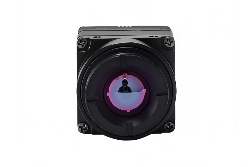
High-Performance Thermal Imaging Module Integration: Edge AI & UAV OEM Solutions
Integrating an uncooled Long-Wave Infrared (LWIR) imaging module into modern autonomous hardware isn't something you just slap together on a Friday afternoon. Look, balancing thermal sensitivity, computational latency, and strict SWaP (Size, Weight, Power, and Cost) constraints is a tough job. OEM engineers building drone payloads, defense recon units, and industrial inspection gear hit serious brick walls when trying to pipe raw infrared sensor feeds straight into hungry neural network accelerators without melting their power budget or blowing past flight weight limits.
Here's the deal: a thermal imaging module is the heart and lungs of your electro-optical setup. It takes long-wave infrared radiation (the 8–14 µm spectrum) and converts thermal energy into a raw digital temperature matrix. In the shop, we don't mess around with bulky, hot-running frame grabbers anymore. Modern setups wire micro-sized Vanadium Oxide (VOx) cores straight into system-on-chip (SoC) platforms through low-latency interfaces like MIPI CSI-2, USB 3.0, or parallel DVP. This technical guide gives you an unvarnished, bench-tested blueprint for wiring compact LWIR thermal camera modules into custom embedded vision platforms, squeezing maximum performance out of edge AI pipelines, and keeping drone payloads rock solid under harsh conditions.
The signal path from glass to telemetry is straightforward once you know where the landmines are buried. Thermal radiation travels through germanium optics onto an uncooled microbolometer focal plane array. The underlying Readout Integrated Circuit (ROIC) converts small voltage changes into a pristine 14-bit digital stream. We pipe that raw Raw14 or formatted YUV422 video directly over MIPI CSI-2 or USB into host platforms like the NVIDIA Jetson Orin, NXP i.MX8, or Raspberry Pi CM4. Custom drivers handle frame grabs via zero-copy DMA buffers, feeding uncompressed thermal data right to TensorRT-optimized YOLO models for real-time target recognition, minefield mapping, or industrial hotspot detection. Standard MAVLink or CAN bus telemetry packages then deliver those spatial coordinates straight to your autopilot or ground station.

Before diving into the schematic details, take a minute to review the high-level system components. You need a clear view of how hardware choices ripple down to processing latency and thermal measurement stability across variable ambient operational environments.
Table of Contents
- 👉 1. Fundamental Physics & Microbolometer Architecture
- 👉 2. High-Speed Digital Interfaces & Signal Protocols
- 👉 3. Radiometric Calibration & Pixel-Level Thermal Analytics
- 👉 4. Edge AI Machine Vision Integration
- 👉 5. UAV Payload Systems Engineering & SWaP-C Optimization
- 👉 6. Commercial OEM Thermal Imaging Module Lineup
- 👉 7. Engineering Deep-Dive FAQ
- 👉 8. Technical Integration Checklist for OEM Engineers
1. Fundamental Physics & Microbolometer Architecture
At its core, an uncooled LWIR imaging module relies on raw thermal kinetic energy rather than photon excitation. Visible spectrum CMOS chips detect light by knocking electrons loose in silicon. Microbolometers, on the other hand, operate by physically absorbing infrared radiation and changing their electrical resistance as they heat up. It's purely thermal, meaning your sensor doesn't care whether it's high noon or pitch black midnight.
Incoming infrared energy hits a micro-machined absorber layer suspended on tiny leg anchors over a silicon substrate. That absorber transfers heat to an active thin film—typically Vanadium Oxide (VOx)—causing a measurable electrical resistance change. The ROIC circuit samples those resistance variations pixel by pixel, turns them into precise voltages, and converts them to digital readout counts. Because those leg anchors are micro-fine to prevent heat escaping into the chip carrier, physical shock and thermal design require serious care during mechanical mounting.
If you want to dig deeper into focal plane array fab techniques, semiconductor leg-anchor design, and micro-cantilever isolation, check out the detailed breakdown on the Wikipedia Microbolometer standard reference.
Vanadium Oxide (VOx) vs. Amorphous Silicon (a-Si)
On the bench, you'll see two main thin-film materials: Vanadium Oxide (VOx) and Amorphous Silicon (a-Si). Let's cut right to the chase: VOx is the clear winner for performance-critical OEM builds. VOx films offer a Temperature Coefficient of Resistance (TCR) around -2.2% to -2.8% per Kelvin at room temperature. That high sensitivity translates to lower spatial noise and faster, cleaner recovery when ambient temperatures shift quickly. Amorphous silicon might save a few pennies during fab because it runs on standard CMOS lines, but its lower TCR means you have to crank the sensor gain way up. That introduces fixed-pattern noise (FPN) and drift issues that'll drive you crazy during field calibration.
Key Performance Parameters
- ⚙️ Pixel Pitch (µm): This is the center-to-center distance between neighboring detector pixels. Moving from older 17 µm pixels down to 12 µm lets you shrink your optics diameter by nearly 30% without giving up resolution. Smaller glass means lighter gimbals, less weight on drone frames, and lower optical production costs.
- ⚡ Noise Equivalent Temperature Difference (NETD): Rated in millikelvins (mK), NETD tells you the smallest thermal difference the camera can pull out of background noise. An NETD <40mK rating means the camera easily picks out fractional-degree shifts. That level of detail is crucial when you're hunting for buried landmines, locating overheating transformer coils, or spotting target signatures through ground fog or heavy dust.
- ⏱️ Time Constant & Frame Rate: Microbolometers have a natural physical heating/cooling lag—the thermal time constant—typically running between 8 mK and 12 mK. Standard exportable modules run at 25 Hz or 30 Hz (or 9 Hz if you're working around restrictive export compliance limits). A steady 30 Hz to 60 Hz frame rate prevents image smear and target tearing during sharp flight turns or high-speed robotic pan/tilt tracking.
2. High-Speed Digital Interfaces & Signal Protocols
Picking the right physical transport interface for a thermal imaging module comes down to a trade-off between latency, CPU overhead, and board routing complexity. In the shop, we routinely see engineering teams pick USB for quick prototyping, only to hit a wall later with frame jitter and high host processor loads during final field testing.
When you route MIPI CSI-2 directly, differential clock and data lines dump Raw14 or YUV frames straight into the host SoC memory block using hardware DMA. It's zero-copy, sub-5 millisecond transport with negligible host CPU usage—making MIPI the hands-down choice for Linux target hardware like NVIDIA Jetson edge boards. USB 2.0/3.0 setups run through an onboard bridge controller, outputting standard UVC video and virtual COM ports. USB offers plug-and-play convenience for x86 industrial PCs, but that UVC stack brings extra protocol overhead, higher power consumption, and potential frame drops when system load spikes.
| Feature / Interface | MIPI CSI-2 | USB 2.0 / USB 3.0 | DVP (Digital Video Parallel) |
|---|---|---|---|
| Data Bandwidth | Up to 2.5 Gbps per lane | 480 Mbps (USB 2) / 5 Gbps (USB 3) | 50 to 150 Mbps |
| CPU Utilization | Extremely Low (Hardware DMA) | Moderate to High (UVC Layer) | Low |
| Cable Length | Short (<20 cm flex PCB) | Medium (<3 to 5 meters) | Very Short (<10 cm) |
| Target Host | NVIDIA Jetson, NXP i.MX, CM4 | x86 Industrial PCs, Custom SoCs | Microcontrollers, Low-power DSPs |
| Interconnects | Board-to-board micro-connectors | Type-C / Micro-USB / Headers | High-density ribbon headers |
When designing ruggedized flight boards subject to heavy engine vibration or thermal shocks, avoid flimsy consumer headers. Experienced hardware teams specify ruggedized micro-fit connectors from proven interconnect suppliers like TE Connectivity to lock down signal integrity and prevent video drops in mid-air.
Raw14 vs. YUV422 Stream Topologies
Depending on what your onboard software needs to accomplish, your thermal core can deliver output data in two primary forms:
- 📊 Raw14 Bit Depth Mode: Streams uncompressed, raw 14-bit digital values straight off the ROIC's internal ADC. You need Raw14 if your host software computes exact surface temperatures, runs multi-frame thermal noise algorithms, or feeds specialized analytical models.
- 🖼️ YUV422 / RGB Mode: The thermal module's internal Image Signal Processor (ISP) handles Non-Uniformity Correction (NUC), applies local contrast algorithms (like CLAHE), and maps the output into display-ready visual palettes (White Hot, Black Hot, Rainbow). This hands back display-ready 8-bit video, taking the rendering load completely off your main processor.
3. Radiometric Calibration & Pixel-Level Thermal Analytics
Radiometry converts a basic grayscale thermal picture into an accurate, pixel-by-pixel surface temperature map. In a calibrated radiometric thermal imaging module, every single pixel acts as a non-contact infrared thermometer, letting you monitor critical thermal thresholds across industrial powerlines, solar farms, or military assets.
Turning raw 14-bit detector counts into reliable temperature readings requires a multi-step calibration pipeline. First, raw sensor responses pass through factory Non-Uniformity Correction (NUC) tables to strip out fixed-pattern detector noise. From there, host software calculates atmospheric losses and surface emissivity corrections, accounting for air temp, distance, and humidity. Finally, these cleaned counts run through pixel-specific polynomial curves to compute exact surface temperatures across the scene.
The Radiometric Measurement Equation
To compute absolute surface temperatures from raw 14-bit data, host algorithms apply mathematical formulations based on Planck's radiation law and the Stefan-Boltzmann law. Total infrared radiance reaching the sensor combines object emissions, reflected ambient energy, and atmospheric radiation:
S_total = τ · ε · S(T_obj) + τ · (1 - ε) · S(T_bg) + (1 - τ) · S(T_atm)
Where the radiometric factors break down as follows:
- ⚙️ ε (Emissivity): Surface radiation efficiency of the target compared to a blackbody (ranging from 0.01 for shiny bare aluminum to 0.98 for flat black paint or organic tissue).
- ⚙️ τ (Atmospheric Transmittance): Transmission factor of the air path between target and lens, calculated from distance, air temperature, and relative humidity.
- ⚙️ T_obj: Calculated absolute temperature of the target object surface.
- ⚙️ T_bg: Reflected background temperature ambient environment.
- ⚙️ T_atm: Temperature of the surrounding air column between target and lens optics.
Calibration Procedures: Shutter vs. Shutterless Non-Uniformity Correction (NUC)
Uncooled microbolometers drift naturally as their internal housing temperature changes during operation. To eliminate spatial fixed-pattern noise (FPN) and retain calibration, thermal cores use one of two NUC methods:
- Mechanical Shutter NUC: A small mechanical blade drops in front of the sensor array for 200–500 milliseconds, giving the microbolometer a uniform thermal baseline. The internal processor recalibrates offset values for every pixel. The downside? The video stream freezes briefly during recalibration, which can mess up high-speed target tracking loops.
- Shutterless SW NUC: Advanced shutterless setups model sensor drift on the fly using internal chassis temperature sensors and temporal frame analysis algorithms. This approach removes mechanical moving parts, cuts power draw, and delivers continuous video without dropped frames—vital for autonomous flight navigation.
For a real-world look at long-range optical assemblies, precision motor drives, and edge AI integration setups, check out our field engineering guide on the 90mm long-range thermal camera core with edge AI capability.
4. Edge AI Machine Vision Integration
Running neural networks directly on raw video streams from a thermal imaging module enables real-time autonomous detection of human signatures, landmines, or electrical equipment failures. Since thermal images lack visual RGB color textures, object detection models rely on spatial intensity gradients, edge contrast, and thermal delta patterns.
In modern edge processing setups, raw 14-bit or 8-bit thermal frames stream straight over MIPI CSI-2 into host DMA memory buffers. The processing pipeline normalizes dynamic ranges, runs local contrast enhancements, and formats inputs for neural networks. Accelerated inference engines run optimized models like TensorRT, outputting bounding boxes, target classes, and coordinate offsets at high frame rates.
Optimizing Edge AI Execution Pipelines
- ⚡ Dynamic Range Normalization: Convert raw 14-bit dynamic data (0 to 16,383) into single-channel 32-bit floating-point tensors scaled between 0.0 and 1.0. Applying Contrast Limited Adaptive Histogram Equalization (CLAHE) before inference highlights subtle surface temperature boundaries, boosting detection accuracy significantly.
- ⚡ Hardware Acceleration (TensorRT / ONNX): Convert object detection networks (like YOLOv8 or YOLOv9) into quantized FP16 or INT8 TensorRT engines. Executing quantized models on edge hardware like the NVIDIA Jetson Orin Nano hits over 60 FPS at 640x512 resolution while drawing under 7 Watts total power.
- ⚡ Multi-Spectral Sensor Fusion: Align and overlay frames from a standard RGB camera core with your thermal module. Combining visual spatial outlines with thermal heat signatures creates reliable perception systems that keep working through heavy smoke, bright reflections, atmospheric haze, or complete night darkness.
For more details on matching camera module specs to industrial environments, read our engineering walkthrough on industrial thermal camera core selection strategies.
5. UAV Payload Systems Engineering & SWaP-C Optimization
Designing drone payloads for multi-rotor or fixed-wing airframes means counting every single gram and milliwatt. Every extra 10 grams on an electro-optical payload shortens hover time and cuts total operational radius.
A typical drone payload pairs a small thermal core with a precision Inertial Measurement Unit (IMU) mounted inside a 3-axis brushless gimbal. The gimbal smooths out high-frequency frame vibration and rotor turbulence. Payload controllers handle target tracking and communicate using MAVLink telemetry sent straight to the flight computer, auto-geotagging identified thermal anomalies with exact GPS coordinates.
Essential Design Rules for Drone Payload Engineers
- 🛠️ Mechanical Damping & Thermal Isolation: Microbolometers are very sensitive to motor vibration frequencies and rapid temperature shifts during altitude climbs. Mount your camera module inside CNC-machined aluminum housings fitted with tuned silicone dampening rings to dissipate internal heat evenly and isolate structural motor hum.
- 🛠️ MAVLink Protocol Synchronization: Inject high-rate flight data (GPS latitude/longitude, altitude, roll, pitch, and yaw) into image metadata headers using MAVLink messages. Real-time spatial metadata lets mapping software piece together orthomosaics and calculate exact ground coordinates for targets.
- 🛠️ Electromagnetic Shielding (EMC): Motor ESCs, switching regulators, and wireless video links generate significant RF noise. Wrap flexible ribbon cables in grounded copper foil shielding and place LC filters on DC power lines to prevent digital noise lines from cluttering your thermal image feeds.
Read our technical feature on high-resolution thermal imaging camera modules for drone payloads for a deeper look at small-footprint sensor layout and flight integration.
6. Commercial OEM Thermal Imaging Module Lineup
Here's a breakdown of current uncooled LWIR camera modules engineered specifically for compact UAV gimbals, landmine detection units, edge machine vision platforms, and custom thermal optics builds.
1. Uncooled LWIR Mini 256*192 Thermal Imaging Camera Module
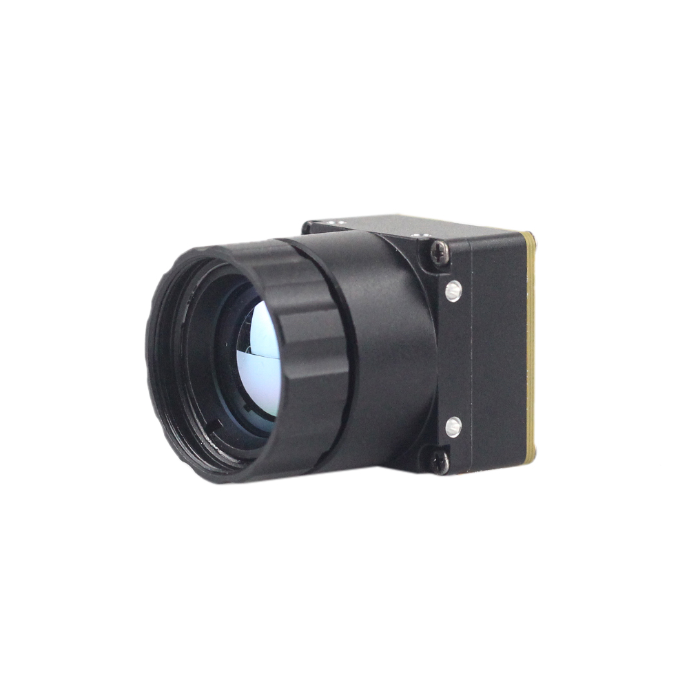
The Mini 256 Uncooled LWIR Thermal Camera Module uses a high-sensitivity VOx microbolometer array to capture long-wave thermal radiation, delivering clean thermal imaging alongside pixel-level temperature measurements. Built for tight spaces, this lightweight camera core outputs consistent thermal frames over multiple interface configurations.
- Resolution & Pitch: 256 × 192 pixels (12 µm VOx detector array)
- Thermal Sensitivity: NETD <40mK for sub-degree temperature accuracy
- Form Factor & Weight: Micro-sized body weighing under 15g for weight-critical systems
- Core Functionality: Full radiometric output capability with raw thermal array data access
2. Uncooled Infrared MIPI 640/384/256 9mm Thermal Imaging Module For Drones

Purpose-built for drone gimbals and autonomous edge vision hardware, the Mini2 Uncooled Infrared Thermal Camera Module delivers high thermal resolution with minimal power draw. Featuring a high-throughput MIPI CSI-2 interface and pre-focused 9mm athermalized optics, it plugs straight into host processors for real-time target recognition and inspection passes.
- Resolution Options: Native 640 × 512 matrix (also available in 384 × 288 and 256 × 192)
- Optical Lens: 9mm pre-focused infrared lens assembly
- Interface Architecture: Low-latency MIPI CSI-2 bus with direct board-to-board connector
- Application Profile: Aerial drone recon, site security, and onboard edge AI processing
Detailed Technical Specifications Comparison Matrix
| Specification Parameter | Mini 256*192 Module | Mini2 640*512 MIPI Module |
|---|---|---|
| Detector Type | Uncooled VOx Microbolometer | Uncooled VOx Microbolometer |
| Array Resolution | 256 × 192 pixels | 640 × 512 pixels (384/256 opt.) |
| Pixel Pitch | 12 µm | 12 µm |
| Spectral Range | 8 µm to 14 µm (LWIR) | 8 µm to 14 µm (LWIR) |
| Thermal Sensitivity (NETD) | <40 mK (@25°C, F#1.0) | <40 mK (@25°C, F#1.0) |
| Video Interface | USB / DVP / Serial | MIPI CSI-2 / Board-to-Board |
| Optics Assembly | Integrated Fixed Lens | 9 mm Athermalized Lens |
| Radiometric Measurement | Full Frame Radiometric Map | Full Frame Radiometric Map |
| Target Primary Use | Mine Detection, Handheld Scopes, Micro-Drones | UAV Inspection, Search & Rescue, Edge AI |
7. Engineering Deep-Dive FAQ
How do I integrate a thermal imaging module with microcontrollers or custom platforms without software driver issues?
If you're targeting low-power microcontrollers without full operating systems (like an STM32H7 or ESP32-S3), pick modules offering Digital Video Parallel (DVP) or SPI outputs. These let you dump raw pixel streams straight into memory using Direct Memory Access (DMA). Vendors supply lightweight C/C++ SDK libraries with helper functions to parse 14-bit data, write configuration registers over I2C/UART, and extract calibrated temperature values with minimal code footprint.
What is the recommended thermal camera module for drone payloads and DIY monocular projects under a reasonable budget?
For commercial aerial inspection, long-range search and rescue (SAR), or high-altitude mapping where detail is critical, step up to the Uncooled Infrared MIPI 640x512 9mm Thermal Module. Its 640x512 matrix provides four times the pixel count of 256x192 cores, letting operators identify targets at much greater slant ranges. Its MIPI CSI-2 link streams raw thermal video directly to onboard host processors for real-time edge processing.
Can small-form-factor thermal imaging modules perform accurate radiometric temperature measurement?
To maintain measurement precision across varying ambient conditions, embedded thermistors track internal housing temperatures in real time. Compensation math dynamically adjusts offset curves to eliminate thermal drift as the module warms up or cools down. By updating target emissivity, ambient temperature, and distance parameters in the host software SDK, system builders can achieve accurate non-contact measurements ideal for electrical grid monitoring, building diagnostics, and field threat detection.
8. Technical Integration Checklist for OEM Engineers
Before locking down your PCB layouts or finalizing custom gimbal designs, verify your implementation against this bench integration checklist:
- ✅ Power Supply Decoupling: Ensure power rail ripple on 3.3V or 5V DC lines powering the thermal module stays below 15mV peak-to-peak. Excessive rail noise creates horizontal fixed-pattern banding across thermal frames.
- ✅ MIPI Bus Impedance Control: Verify high-speed MIPI CSI-2 PCB trace differential impedance is tuned to a strict 100 ohms across all clock and data line pairs.
- ✅ Chassis Thermal Path: Provide a direct metal-to-metal heat conduction path from the core housing to your main frame to avoid sensor thermal saturation during long operation cycles.
- ✅ Lens Optical Calculations: Confirm lens focal lengths (9mm, 13mm, 19mm) fulfill Johnson's Criteria requirements for Detection, Recognition, and Identification (DRI) ranges against target profiles.
- ✅ Radiometric Parameter Setup: Verify target surface emissivity inputs are dynamically updated in software based on real-world target materials.
📚 References & Further Reading
- Industry Standard: Wikipedia Microbolometer Fundamentals
- Component Infrastructure: TE Connectivity Precision Connectors
- Related Technical Guide: 90mm Long-Range Thermal Core Architecture
- Related Technical Guide: Industrial Thermal Camera Core Selection Guide
- Related Technical Guide: High-Resolution Drone Thermal Camera Module Engineering