High-Performance Thermal Imaging Module Integration: Edge AI & UAV OEM Solutions
2026年8月12日
Commercial Uncooled Thermal Sensor Modules: High-Res OEM & Edge AI Integration Guide
2026年8月13日
High-Performance Thermal Imaged Module Selection Guide for OEM & Drones
When you're engineering systems for autonomous robotics, aerial surveillance, or industrial predictive maintenance, integrating an enterprise-grade thermal imaged module isn't just a nice feature to show off—it's an essential architectural choice. Modern electro-optical systems have to deliver clear thermal data through harsh atmospheric environments, thick smoke, fog, and zero-light conditions. But here's the reality: squeezing an uncooled long-wave infrared (LWIR) core into space-constrained UAV gimbals, handheld inspection gear, or automated security payloads means balancing optical performance, thermal sensitivity, processing latency, and physical footprint. As optical system engineers, we constantly make tough trade-offs—like balancing pixel pitch against lens aperture, or picking lightweight ASIC processing boards over full-featured radiometric SDK platforms to keep a project on target.
Getting real thermal imaging efficiency comes down to optimizing SWaP-C (Size, Weight, Power, and Cost) without destroying detector performance. Whether you're building defense drones with autonomous target recognition or setting up industrial IoT thermal sensors for 24/7 substation monitoring, choosing the right core requires a solid grip on microbolometer physics, interface standards (RTSP over IP vs. ultra-low latency CVBS analog), and non-uniformity correction (NUC) algorithms. This selection guide breaks down the core principles, engineering workflows, and real-world specs you need to integrate OEM thermal camera engines into custom hardware setups.
Table of Contents
- 👉 1. Phase-Engineered Thermal Imaged Module Fundamentals
- 👉 2. SWaP-C Optimization Strategy for UAV & Autonomous Payloads
- 👉 3. Dynamic Video Interface Engineering: RJ45 RTSP vs. CVBS Analog
- 👉 4. Comprehensive OEM Product Benchmarking & Specs Engine
- 👉 5. Optical Calibration, NUC, and Temperature Measurement Metrics
- 👉 6. Industrial Technical FAQ Directory
1. Phase-Engineered Thermal Imaged Module Fundamentals
An imaged module using long-wave infrared (LWIR) tech works by capturing thermal radiation emitted by surface objects within the 8 μm to 14 μm spectral band. Unlike standard optical sensors that need ambient light, an uncooled thermal microbolometer array detects blackbody radiation differences and turns raw kinetic heat into clear digital thermal maps. This independence from visual light makes an infrared camera engine indispensable for dark operations, search-and-rescue (SAR) missions, electrical cabinet checks, and early fire detection setups.
To understand how heat turns into a usable video feed or radiometric temperature grid, let's walk through the hardware pipeline step-by-step:
- ⚙️ Germanium / Chalcogenide Optics: Standard optical glass blocks infrared light completely. So, an infrared core relies on anti-reflective (AR) coated Germanium or Chalcogenide lenses engineered to pass 8–14 μm photons while suppressing optical distortions.
- ⚙️ Uncooled Microbolometer Detector Array: Infrared radiation passes through the lens and hits a tiny suspended microbolometer array made of heat-sensitive materials. As photons warm the suspended bridges, their electrical resistance changes directly based on the material's Temperature Coefficient of Resistance (TCR).
- ⚙️ Readout Integrated Circuit (ROIC): Right below the microbolometer matrix sits a CMOS ROIC. The ROIC samples resistance shifts pixel by pixel, turning microscopic electrical variations into clean digital counts.
- ⚙️ Onboard Processing Engine (ASIC/FPGA): The digital count feeds into a dedicated onboard processor. Here, non-uniformity correction (NUC), bad pixel replacement (BPR), noise filtering, and dynamic range algorithms run in real time to yield clean, high-contrast video or calibrated temperature profiles.
- ⚙️ Multi-Protocol Interface Backend: Finally, the backend packages the video or radiometric telemetry into standardized outputs—like zero-latency CVBS analog feeds or IP-based RTSP/ONVIF streams over RJ45 Ethernet.
Core Detector Physics: VOx vs. a-Si
At the center of any modern OEM thermal engine sit Vanadium Oxide (VOx) or Amorphous Silicon (a-Si) thin-film resistors mounted on a micro-machined silicon ROIC. Choosing between these materials is one of the biggest calls you'll make when picking hardware:
- ✅ Vanadium Oxide (VOx): VOx microbolometers offer a significantly higher Temperature Coefficient of Resistance (TCR). In simple terms: higher electrical sensitivity, lower noise, and solid long-term stability. VOx is the gold standard for high-precision industrial inspection, defense payloads, and enterprise drone gear where picking up sub-degree temperature differences matters.
- ✅ Amorphous Silicon (a-Si): Amorphous silicon gives solid uniform spatial response across the focal plane and keeps production costs down in high-volume runs. While a-Si cores generally run slightly less sensitive than VOx, their lower price point makes them ideal for commercial security systems and budget consumer tools.
Spatial Resolution and Pixel Pitch Dynamics
Array resolution dictates spatial detail, field of view (iFOV), and spatial Detection, Recognition, and Identification (DRI) ranges based on standard Johnson's criteria:
| Array Format | Total Pixel Count | Optimal Deployment Scenarios | Optical & SWaP Impact |
|---|---|---|---|
| 384×288 Array | 110,592 Pixels | Micro-drones, handheld tools, short-range perimeter monitoring | Lightweight footprint, minimal power draw, compact lens options |
| 640×512 Array | 327,680 Pixels | Enterprise SAR drones, high-altitude tactical payloads, power station inspection | Nearly 3x pixel count, extended DRI distances, wider horizontal view |
Along with array resolution, pixel pitch—measured in micrometers (μm)—defines center-to-center spacing between neighboring detector elements. Moving from legacy $17\mu m$ sensors to advanced $12\mu m$ microbolometers has been a massive win for flight payload designs. Dropping to $12\mu m$ reduces the optical focal length needed for the same magnification factor. That means you can trim lens diameter and mass by 30% to 40% without losing range performance. For a deeper breakdown on integrating cores across multi-sensor units, read our LTC Multi-Functional Thermal Camera Module Integration Guide.
Thermal Sensitivity (NETD) and Frame Refresh Rates
Two major specs determine how good your output video looks under real field conditions:
- ⚙️ Noise Equivalent Temperature Difference (NETD): Measured in millikelvins (mK), NETD marks the smallest temperature variation the sensor can pick up over baseline detector noise. A module rated at $\le 30\text{ mK}$ or $\le 40\text{ mK}$ will reveal subtle thermal boundaries—like wet building insulation or thin traces heating up on a PCB—much better than a budget core rated at $\ge 50\text{ mK}$.
- ⚙️ Frame Refresh Rates (25Hz / 30Hz / 50Hz / 60Hz): High frame rates are non-negotiable for stabilizing aerial gimbals and tracking fast-moving targets. While 9Hz cores bypass strict Wassenaar export rules, serious tactical and tracking applications require $\ge 30\text{Hz}$ or $50\text{Hz}$ to eliminate motion blur during fast drone turns.
2. SWaP-C Optimization Strategy for UAV & Autonomous Payloads
When you're fitting an OEM thermal camera engine into a drone, autonomous robot, or handheld rig, every gram and milliwatt counts. Extra mass cuts flight time down immediately, while excess heat build-up inside a sealed gimbal enclosure degrades detector sensitivity over time.
Here's how experienced payload engineers manage SWaP-C across hardware builds:
| SWaP-C Constraint | Primary Engineering Bottleneck | Architectural Solution Strategy |
|---|---|---|
| Physical Size & Mass | Heavy optic glass and bulky chassis ruin gimbal tuning and cut airframe flight time. | Use 12µm VOx detector arrays; pick CNC magnesium-aluminum or carbon-composite housing. |
| Electrical Power Draw | High power draw eats main flight batteries and causes internal self-heating. | Deploy custom low-power Application-Specific Integrated Circuits (ASICs) (<1.5W power draw). |
| Optical Efficiency | Narrow aperture lenses cut photon collection, degrading overall sensitivity. | Integrate fast F/1.0 to F/1.2 Germanium lenses with hard carbon protective coatings. |
| Edge AI Processing | Streaming raw video to ground stations adds latency and drops under interference. | Mount lightweight AI acceleration chips right onto the thermal board for local object recognition. |
Power Dissipation & Thermal Balance Mechanics
Uncooled microbolometer arrays react quickly to environmental heat shifts. Conductive or radiated heat coming from nearby ESCs, flight controllers, or motors causes shading artifacts across your image. Keeping imagery clear and accurate takes a direct heat management plan:
- ⚙️ ASIC Processing Backends: Swapping out power-hungry FPGAs for dedicated ASIC processors drops core power draw under 1.5 Watts. That keeps heat generation down and prevents internal sensor drift.
- ⚙️ Conductive Thermal Paths: Isolate the microbolometer assembly using thermal conductive pads tied straight to an aluminum outer shell. This dumps excess heat out into the airflow and preserves sensor calibration even during hot summer flights.
For additional details on airframe mounting and flight controller integration, check out the engineering teardowns at OBSETECH Drone Systems Integration. Pair low-power ASIC hardware with local computer vision models to form a reliable baseline for target tracking—a topic covered in our breakdown on Top AI-Powered Thermal Modules for UAV Payloads.
3. Dynamic Video Interface Engineering: RJ45 RTSP vs. CVBS Analog
Selecting the right interface output for a thermal imaged module depends entirely on your system setup. You need to balance resolution, control functions, cabling weight, and acceptable latency for your video pipeline.
Architectural Interface Pathways
An integrated thermal camera core handles raw detector data and outputs video in two primary ways: an RJ45 Ethernet IP Pipeline (delivering compressed H.264/H.265 streams over RTSP/ONVIF directly to custom SDKs and edge AI processors) or an Analog CVBS Interface (delivering low-latency raw video over 2-wire lines directly to FPV monitors and analog transmitters).
1. RJ45 Ethernet Interface (RTSP / IP Video Streaming)
Network-enabled thermal camera modules use hardware encoders (H.264 / H.265) to stream digital video over standard network cabling using RJ45 or compact micro-connectors:
- ⚙️ RTSP (Real-Time Streaming Protocol) Integration: RTSP lets mission computers, ground control stations (GCS), or custom software pull video feeds using straightforward network URIs (like
rtsp://192.168.1.100/live/main). This simplifies software design and allows multiple apps to read the same stream. - ⚙️ ONVIF Profile S Compliance: Standard ONVIF compliance means plug-and-play setup with commercial VMS platforms, security networks, and monitoring gear without writing custom drivers.
- ⚙️ Telemetry Overlays & Command Control: Ethernet supports two-way communication on a single cable harness. You can tweak color palettes, trigger non-uniformity correction cycles, and pull pixel-by-pixel radiometric data while video runs.
2. CVBS (Composite Video Blanking and Sync) Analog Interface
Even with advanced IP options available, plain analog CVBS video remains critical for fast tactical flying and low-weight gimbal setups:
- ✅ Near-Zero Latency Transmission: By skipping compression buffers, analog CVBS feeds video straight to ground screens with less than 10ms of delay. That instant visual response is essential for manual drone piloting in tight spaces.
- ✅ Simplified Wiring Harness: Standard SD analog video runs over a basic two-wire connection (Signal + Ground). This lightweight setup makes it easy to route cabling through compact 360-degree gimbal slip rings.
Comprehensive Interface Technical Comparison
| Performance Feature | RJ45 Ethernet (IP RTSP Stream) | CVBS (Analog Output) |
|---|---|---|
| Video Stream Latency | 100ms – 220ms (Depending on encoding buffer) | < 10ms (Near-Zero Latency) |
| Resolution Support | Native Array Resolution (640×512, 1024×768) | Standard Definition (NTSC 720×480 / PAL 720×576) |
| Cabling Harness Footprint | 4-wire / 8-wire Ethernet twisted pair | 2-wire Lightweight Micro-Pin Cable |
| Software Integration Ease | High (Direct OpenCV, Python, C++ socket access) | Requires hardware capture card on PC host |
| Telemetry Transmission | Integrated (Temperature data multiplexed over IP) | Limited (Visual OSB text overlays only) |
4. Comprehensive OEM Product Benchmarking & Specs Engine
To help you pick the right module, here are two of our uncooled OEM thermal camera engines designed specifically for drones, gimbals, and automated industrial equipment.
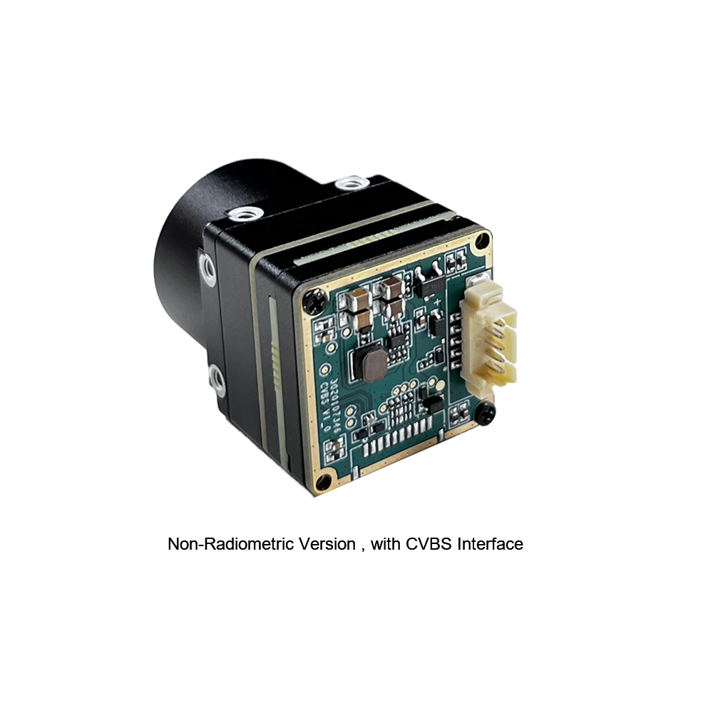
Uncooled Mini 384*288 Thermal Camera Module For Drones
The MINI series infrared thermal imaging module is a compact, high-precision thermal imager designed for direct integration. Featuring a sensitive detector core, stable performance, and essential system interfaces, it fits right into machine vision, drone payloads, automated safety inspections, and equipment monitoring platforms.
Technical Specification Breakdown
| Core Detector Array | 384 × 288 High-Sensitivity Uncooled Microbolometer |
| Video Interface Format | Analog CVBS Output with low-latency signal routing |
| Form Factor & SWaP | Ultra-miniaturized body designed for lightweight airborne gimbals |
| Primary Deployments | Machine vision, safety inspection, smart manufacturing, drone payloads |

Uncooled Infrared RJ45 CVBS RTSP IP 640*512 Thermal Sensor Camera Module
Powered by a high-efficiency ASIC processing core, this 640*512 thermal imaging camera module delivers detailed resolution alongside dual RJ45 Ethernet IP and CVBS analog outputs. Built specifically for long-range UAV search-and-rescue, site surveillance, and edge AI video pipelines.
Technical Specification Breakdown
| Core Detector Array | 640 × 512 High-Resolution Uncooled Microbolometer |
| Processing Architecture | Dedicated Low-Power Hardware ASIC Processing Core |
| Interface Ecosystem | RJ45 Ethernet (RTSP / IP) + Concurrent CVBS Analog Output |
| Primary Deployments | Enterprise drone systems, edge AI video platforms, long-range SAR |
Master OEM Thermal Module Comparison Matrix
| Product Model | Visual Reference | Array Resolution | Connectivity Profiles | Target Application Focus | Direct Datasheet Link |
|---|---|---|---|---|---|
| Uncooled Mini 384*288 Thermal Camera Module For Drones |
|
384 × 288 Pixels Microbolometer |
• Analog CVBS Output • Compact Pin Headers |
• Lightweight drone gimbals • Smart manufacturing • Machine vision inspection |
Open Specs ➔ |
| Uncooled Infrared RJ45 CVBS RTSP IP 640*512 Thermal Module |
|
640 × 512 Pixels ASIC Engine Core |
• RJ45 IP (RTSP / ONVIF) • Concurrent Analog CVBS |
• High-altitude SAR drones • Automated AI vision analytics • Perimeter monitoring |
Open Specs ➔ |
5. Optical Calibration, NUC, and Temperature Measurement Metrics
Getting clean image feeds out of an uncooled imaged module takes solid calibration. Microbolometers react constantly to external temperature shifts. Without active image corrections, your video stream will degrade and thermal measurements will drift off target.
Non-Uniformity Correction (NUC) Mechanics
Because micro-fabrication isn't 100% uniform across an array, every single pixel on a microbolometer has slightly different gain and resistance characteristics. Add in internal warmth from driving electronics, and you get fixed-pattern noise (FPN) and vertical streaks across your image if it isn't corrected.
- ⚙️ Mechanical Shutter Calibration (Shutter-Based NUC): The module drops a mechanical shutter flag in front of the array for a fraction of a second, presenting a flat, uniform thermal baseline. The DSP uses this event to reset pixel gain offsets. It works well, but it causes a brief video pause (about 200ms–500ms), which can disrupt auto-tracking algorithms.
- ⚙️ Shutterless Scene-Based NUC Algorithms: Modern modules run intelligent shutterless NUC routines. These mathematical models evaluate scene motion along with internal temperature sensors on the ROIC board to update offset values continuously. You get smooth, uninterrupted video feeds—critical for fast tactical drone operations.
Radiometric Temperature Measurement Math
It's important to differentiate between visual thermal cores (built for high-contrast viewing) and full radiometric temperature measurement engines. Radiometric cores calculate true target surface temperatures across every single pixel by factoring in atmospheric losses and target surface emissivity.
The total heat radiance ($W_{\text{total}}$) picked up by a microbolometer pixel follows the Stefan-Boltzmann radiometric transport model:
Where:
- ⚙️ τ (Tau): Atmospheric transmittance factor along the line-of-sight path.
- ⚙️ ε (Epsilon): Surface emissivity coefficient of the target material (e.g., bare shiny metal $\approx 0.05$, matte paint $\approx 0.95$).
- ⚙️ σ (Sigma): The Stefan-Boltzmann constant ($5.670374 \times 10^{-8} \text{ W/m}^2\text{K}^4$).
- ⚙️ T_target: Absolute target temperature (Kelvin).
- ⚙️ T_ambient: Reflected background temperature (Kelvin).
- ⚙️ T_atmosphere: Ambient air temperature along the path (Kelvin).
By solving this balance equation continuously inside the ASIC firmware, radiometric cores generate accurate temperature readings across changing outdoor conditions. For a broader look at adapting standard camera designs for thermal operation, read our overview on Converting Standard Optical Engines to Thermal Imaging Systems.
6. Industrial Technical FAQ Directory
How can I stream video from an IP-enabled thermal imaged module into a custom OpenCV processing pipeline?
Connecting an IP-enabled module—like the Uncooled Infrared RJ45 CVBS RTSP IP 640*512 Module—into a custom computer vision pipeline is straight forward over local network lines. The onboard hardware encoder outputs standard H.264 or H.265 streams accessible via RTSP URIs.
Here is a battle-tested Python setup using OpenCV to pull frames directly into memory:
import cv2

# Module RTSP network endpoint
rtsp_stream_uri = "rtsp://192.168.1.100/live/main"

# Initialize capture stream via FFMPEG backend
cap = cv2.VideoCapture(rtsp_stream_uri, cv2.CAP_FFMPEG)

if not cap.isOpened():
    print("Error: Unable to connect to thermal module stream.")
    exit()

while True:
    ret, frame = cap.read()
    if not ret:
        print("Error: Frame capture failed.")
        break

    # Process thermal frame (e.g., edge detection, target identification)
    gray_thermal = cv2.cvtColor(frame, cv2.COLOR_BGR2GRAY)

    # Render processed thermal frame
    cv2.imshow("OEM Thermal Module RTSP Stream", gray_thermal)

    if cv2.waitKey(1) & 0xFF == ord('q'):
        break

cap.release()
cv2.destroyAllWindows()
If you're running edge analytics, push this script to an embedded platform like an NVIDIA Jetson module mounted right next to the camera core to run real-time target detection models directly on incoming RTSP frames.
What critical criteria dictate thermal core selection for miniature UAV gimbal payloads?
Choosing an OEM thermal engine for lightweight drone gimbals requires balancing four core requirements:
- ⚙️ SWaP Constraints (Size, Weight, Power): Payload weight drops airframe flight times fast. Pick low-power ASIC cores (<1.5W draw) to keep battery drain down and prevent heat build-up inside tight gimbal shells.
- ⚙️ Resolution and Pixel Pitch: For close-up or low-altitude work, a 384×288 array gets the job done cleanly. For higher altitude flights or search-and-rescue work, go with a 640×512 array with 12µm pixel pitch to maintain high spatial detail at a distance.
- ⚙️ Video Latency & Control Interface: Manual piloting needs low delay—use analog CVBS (<10ms) for real-time control. For onboard AI tracking, feed high-resolution RTSP streams straight into your compute hardware.
- ⚙️ Ruggedization: Drone payloads take plenty of shock, vibration, and thermal exposure. Verify the thermal core supports extended operational ranges (-40°C to +80°C) with rigid mounting locations to keep optics aligned under heavy flight loads.
How do radiometric thermal camera modules differ operational-wise from standard thermal imaging cores?
The difference between standard thermal engines and radiometric thermal engines comes down to raw data processing and absolute temperature reporting:
Standard Thermal Camera Modules: These are built purely for image visual quality. They use Automatic Gain Control (AGC) curves to enhance image contrast, making targets pop against colder backgrounds. However, standard cores don't measure calibrated temperature values—pixel brightness simply shows relative heat contrast in the scene.
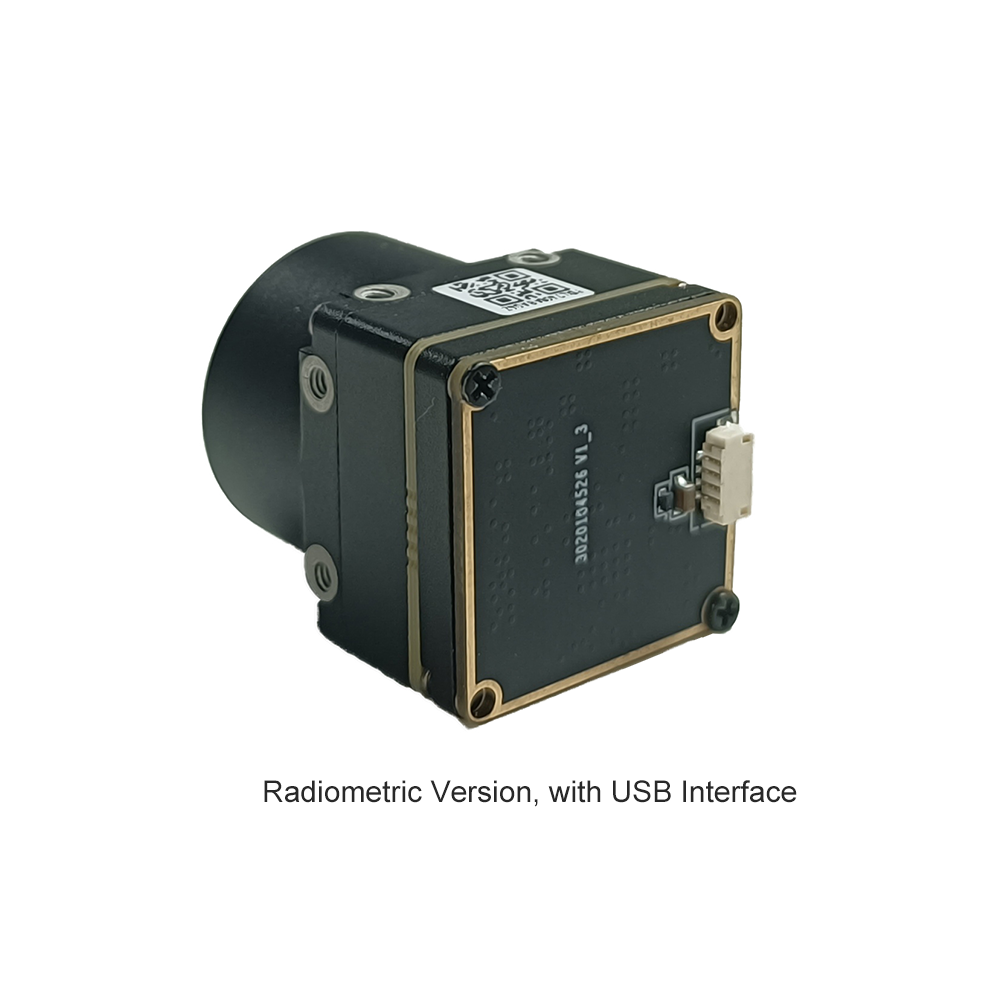
Radiometric Thermal Camera Modules: Radiometric cores maintain continuous factory and sensor-level thermal calibrations for every pixel on the detector array. By factoring in surface emissivity, distance, atmospheric loss, and ambient humidity, radiometric modules calculate real surface temperatures across the image. That makes them mandatory for utility inspections, solar panel checks, and fire monitoring applications where exact target temperatures are required.
How do optical lens parameters (Focal Length and F-Number) impact thermal range and NETD sensitivity?
The front optics act as the primary light collector, setting strict physical limits on spatial range and system noise:
Focal Length ($f$): Focal length directly dictates field of view (FOV) and optical magnification. Longer focal lengths narrow the view, focusing pixel density on distant targets to boost Detection, Recognition, and Identification (DRI) ranges. But keep in mind: long Germanium lenses add mass and footprint quickly, which can challenge strict SWaP limits.
Lens Aperture ($F$-Number): The $F$-number marks the light-gathering speed of the lens setup. Lower $F$-numbers (e.g., $F/1.0$ vs $F/1.4$) let significantly more infrared energy reach the microbolometer array. Opening up the aperture improves overall system thermal sensitivity (lower effective NETD), providing cleaner frames in low-contrast conditions. For enterprise setups, an $F/1.0$ to $F/1.2$ lens offers the ideal performance balance.
📚 References & Further Reading
- Industry Standard: OBSETECH Advanced Drone Platform Integrations
- Related Guide: LTC Multi-Functional Thermal Module Architecture Analysis
- AI Integration Manual: Top Thermal Camera Modules for UAV AI Processing Systems
- Technical Reference: Adapting Standard Electro-Optical Engines to Infrared Cores