UAV Infrared Thermal Camera Core Guide: OEM Integration, SWaP & Protocols
2026年9月29日
Best Industrial Inspection Thermal Camera Module: OEM Integration Guide
Thermal imaging has shifted from a specialized, standalone diagnostic instrument to an indispensable embedded sub-assembly in mission-critical manufacturing, automated condition monitoring, and robotic inspection platforms. For electrical enclosures prone to phase imbalances, mechanical gearboxes operating near critical friction thresholds, or utility drones tracing high-voltage transmission lines, continuous thermal visibility eliminates costly catastrophic downtime. Choosing the right industrial inspection thermal camera module requires navigating complex trade-offs between optical physics, sensor architecture, digital communication protocols, and edge compute capabilities.
Integrating an uncooled Long-Wave Infrared (LWIR) core directly into an original equipment manufacturer (OEM) housing demands more than simply routing video signals over USB or MIPI. Systems engineers must evaluate pixel pitch, detector chemistry, thermal drift compensation, spatial resolution, and optical field of view (FOV). This definitive OEM integration guide breaks down the core engineering principles of uncooled LWIR cores, analyzes mechanical and electronic interfacing, details edge AI telemetry integration, and highlights field-proven modules designed for next-generation automated thermal inspection platforms.
Table of Contents
- 👉 1. Uncooled LWIR Detector Physics: VOx, Pixel Pitch, and NETD
- 👉 2. Optical Engineering: Germanium Lenses, Chalcogenide, and Spatial Resolution (IFOV)
- 👉 3. Electrical & Embedded Interfacing: MIPI-CSI2, USB-C, and Industrial Fieldbuses
- 👉 4. Absolute Radiometry, NUC Shuttering, and Thermal Drift Mitigation
- 👉 5. Featured Industrial Modules: Specifications & Comparative Analysis
- 👉 6. Machine Vision & Edge AI: Automated Hot-Spot Tracking and Fault Classification
- 👉 7. Mechanical Packaging, Thermal Dissipation, and Harsh-Environment Hardening
- 👉 8. Deep-Dive OEM Integration FAQ
1. Uncooled LWIR Detector Physics: VOx, Pixel Pitch, and NETD
At the foundation of every modern industrial inspection thermal camera module is the uncooled microbolometer focal plane array (FPA). Unlike cooled medium-wave infrared (MWIR) detectors that rely on integrated Stirling cryocoolers operating down to 77 Kelvin, uncooled sensors detect electromagnetic radiation in the long-wave infrared band spanning from 8 µm to 14 µm at ambient device temperatures. This passive detection approach eliminates bulky thermodynamic cooling mechanisms, slashing size, weight, power, and cost (SWaP-C), while granting systems the structural durability required for years of continuous deployment across automated manufacturing plants, airborne gimbals, and automated optical inspection (AOI) machinery.
The operational physics of the microbolometer relies on energy absorption causing measurable electrical changes. Incident long-wave infrared radiation passes through an optimized optical train and strikes an array of micro-machined absorber membranes. Each individual microbolometer pixel consists of an infrared-absorptive material layer suspended above a silicon substrate via microscopic legs that provide extreme thermal isolation. When photon flux strikes the suspended membrane, its temperature increases. This micro-thermal swing modulates the electrical resistance of the thin-film layer, which is subsequently converted into an electrical voltage or current signal by the underlying silicon Readout Integrated Circuit (ROIC) via an array of analog-to-digital converters (ADCs).

Material Matrix: Vanadium Oxide (VOx) vs. Amorphous Silicon (a-Si)
The specific material deposited onto the suspended membrane fundamentally determines the performance envelope of the industrial inspection thermal camera module. In modern OEM optoelectronics, the market is divided between Vanadium Oxide (VOx) and Amorphous Silicon (a-Si):
- ⚙️ Vanadium Oxide (VOx): VOx thin films deliver an exceptional Temperature Coefficient of Resistance (TCR), typically operating between -2% and -3% per Kelvin. VOx microbolometers exhibit substantially lower 1/f low-frequency flicker noise, higher thermal responsivity, and faster thermal relaxation time constants (commonly 8 to 12 ms). Consequently, VOx is the industry standard for high-precision radiometric condition monitoring, gas leakage surveying, and micro-crack electrical fault diagnostics where discerning thermal deltas as fine as 0.04°C (40 mK) is non-negotiable.
- ⚙️ Amorphous Silicon (a-Si): Amorphous silicon layers can be deposited using standard, high-volume CMOS semiconductor manufacturing equipment. While this offers cost and scaling advantages in mass consumer electronics, a-Si exhibits higher inherent electrical noise, a poorer TCR (often -1.5% to -2.0% per Kelvin), and longer thermal response times. In high-speed industrial inspection, a-Si arrays are more susceptible to image lag, motion blur, and baseline thermal drift under volatile ambient temperature swings.
Pixel Pitch Dynamics and ROIC Scaling
Thermal microbolometer architectures have evolved through continuous micro-fabrication scaling, progressing from legacy 25 µm and 17 µm nodes down to state-of-the-art 12 µm pixel pitches. Shrinking the pixel pitch allows optical designers to reduce the physical diameter and focal length of costly monocrystalline Germanium lenses while preserving spatial resolution. A 12 µm 640×512 array occupies less than half the physical surface area of an equivalent 17 µm array, drastically reducing the physical payload profile for aerial drone gimbals and compact machine vision heads.
However, from a thermodynamic perspective, reducing pixel pitch decreases the active photon-collecting surface area by over 50% when stepping down from 17 µm to 12 µm. To prevent a catastrophic drop in the signal-to-noise ratio (SNR), high-grade OEM modules introduce advanced ROIC architectures featuring 3D folded leg designs, sub-surface mirror cavities to reflect unabsorbed photons back through the active layer, and ultra-high-vacuum hermetic packaging. These enhancements maintain a fill factor exceeding 80%, providing superior radiometric sensitivity despite the ultra-miniaturized physical footprint.
Noise Equivalent Temperature Difference (NETD)
The defining sensitivity metric of any industrial inspection thermal camera module is Noise Equivalent Temperature Difference (NETD), expressed in milliKelvins (mK). NETD quantifies the minimum temperature difference between an object and its surroundings that produces an electrical signal equivalent to the inherent RMS electronic noise of the focal plane array. Formally, NETD is expressed as:
NETD = V_n / [ (dV_s / dT) × τ_optics × (1 / (4 × F#^2)) ]
Where V_n represents system RMS noise voltage, dV_s / dT denotes the detector's responsivity with respect to temperature, τ_optics is optical transmission efficiency, and F# is the lens f-number. An industrial module rated at <40 mK (at f/1.0 and 25°C) can clearly resolve thermal differentials down to 0.04°C. In predictive maintenance contexts—such as tracing early phase imbalances across medium-voltage switchgear busbars, detecting bearing friction in automated conveyor pulleys, or localizing fluid friction inside chemical pipeline valves—a low NETD provides the signal fidelity needed to flag anomalies weeks before catastrophic physical failure occurs.
2. Optical Engineering: Germanium Lenses, Chalcogenide, and Spatial Resolution (IFOV)
Optical design dictates an inspection system’s spatial measurement precision, maximum working distance, and optical throughput. Because conventional optical glasses like borosilicate and fused silica are entirely opaque within the 8 µm to 14 µm LWIR spectrum, specialized infrared optical materials must be selected, shaped, and coated to focus long-wave thermal energy without severe chromatic or spherical aberrations.
Lens Materials: Monocrystalline Germanium vs. Molded Chalcogenide
Industrial imaging cores depend on two primary substrate classes for optical transmission:
- ⚙️ Monocrystalline Germanium (Ge): Germanium possesses an exceptionally high index of refraction (approximately 4.0 at 10 µm), allowing optical engineers to design thin, lightweight lens geometries with minimal curvature and low spherical aberration. However, Germanium exhibits significant absorption shifts when subjected to elevated temperatures and suffers from catastrophic thermal runaway around 100°C, where it becomes functionally opaque. Modules targeted for high-temperature metallurgy inspection, furnace monitoring, or continuous desert utility tracing require specialized Diamond-Like Carbon (DLC) external coatings and temperature-compensated athermal barrel mounts.
- ⚙️ Chalcogenide Glass: Chalcogenide glasses are amorphous compounds composed of heavy chalcogen elements (sulfur, selenium, and tellurium). Unlike Germanium, Chalcogenide glasses can be precision-molded into complex aspheric and diffractive surface profiles at lower mass-production costs. Furthermore, Chalcogenide exhibits a low change in refractive index with respect to temperature (dn/dT), allowing engineers to passively athermalize optical barrels across a wide industrial thermal operating envelope (-40°C to +85°C) without motorized focus-correction mechanisms.
Spatial Calculations: Instantaneous Field of View (IFOV) and MFOV
Specifying the proper focal length for an industrial inspection thermal camera module requires a clear calculation of Instantaneous Field of View (IFOV). The IFOV defines the physical angular area captured by a single microbolometer pixel and dictates spatial sampling capability:
IFOV (in milliradians) = [ Pixel Pitch (p) / Lens Focal Length (f) ] × 1000
To calculate the physical linear spot size (S) projected by one pixel at an inspection standoff distance (D):
S = D × ( p / f )
While IFOV defines spatial resolution, it does not guarantee accurate absolute temperature measurement. Because optical diffraction, lens aberrations, and cross-pixel heat dissipation smear incident radiation across adjacent pixels, accurate radiometry requires calculating the Measurement Instantaneous Field of View (MFOV). The MFOV represents the minimum physical target area required to capture at least 95% to 99% of the incident radiant energy.
As an industrial engineering standard, reliable radiometry requires a target to cover at least a 3×3 to 4×4 contiguous block of detector pixels. Attempting to measure the temperature of an electrical trace, an IC package, or a remote powerline insulator using a single pixel leads to spatial optical dilution, blending target energy with surrounding background temperatures and reporting falsely attenuated readings.
For example, an engineer inspecting a high-voltage utility pole bushing from an airborne drone at a standoff distance of 15 meters using a 12 µm pixel pitch sensor paired with a 9 mm focal length lens achieves an IFOV of 1.33 mrad. At 15 meters, each pixel covers a physical dimension of 20 mm. Under the 3×3 MFOV rule, the minimum target size for certified temperature accuracy is 60 mm. If the target bushing hotspot is smaller than 60 mm, the system requires either closer inspection proximity or a longer focal length optic (such as a 19 mm or 25 mm lens) to narrow the angular view and maintain radiometric integrity.
3. Electrical & Embedded Interfacing: MIPI-CSI2, USB-C, and Industrial Fieldbuses
Integrating an uncooled thermal module into an OEM host requires low-latency raw radiometric transmission and stable electrical interconnects. The choice of interface directly impacts the host processor’s CPU overhead, maximum transmission distance, cable flex durability, and integration footprint.
| Interface Protocol | Data Bandwidth | Transport Latency | Maximum Cable Run | Primary Industrial Use Case |
|---|---|---|---|---|
| MIPI-CSI2 (2/4-Lane) | Up to 2.5 Gbps per lane | < 2 milliseconds | < 15 cm (Trace/Flex) | Drone gimbals, embedded Edge-AI compute (Jetson, NXP, RK) |
| USB 3.0 / USB-C (UVC) | Up to 5.0 Gbps | 8 – 15 milliseconds | Up to 3.0 meters | Handheld diagnostic tools, benchtop test fixtures, automated kiosks |
| GigE Vision (PoE) | 1.0 to 10.0 Gbps | 10 – 25 milliseconds | Up to 100 meters | In-line factory automation, continuous plant monitoring, AOI lines |
| Parallel (DVP) / SPI | 10 to 50 Mbps | 25 – 50 milliseconds | < 10 cm board-to-board | Low-cost microcontrollers, simple thermal threshold telemetry |
Implementing Low-Latency MIPI-CSI2 Lanes
For high-performance embedded systems running processors such as the NVIDIA Jetson Orin, Rockchip RK3588, or Raspberry Pi Compute Module 4, MIPI Camera Serial Interface 2 (MIPI-CSI2) is the preferred physical integration bus. Unlike USB or Ethernet solutions that wrap payload packets inside multiple protocol layers, MIPI-CSI2 pipes uncompressed 14-bit or 16-bit radiometric frame buffers directly into the host SoC’s internal Video Input (VI) subsystem via Direct Memory Access (DMA).
Because the MIPI bus operates at high differential signal frequencies, PCB routing demands strict impedance matching (100Ω differential trace pairs) and trace length tuning to prevent phase skew between clock and data lanes. To guarantee signal integrity across dynamic mechanical environments like dual-axis drone gimbals or continuous robotic arms, design engineers rely on proven, noise-shielded board-to-board connectors and flexible flat cabling from specialized manufacturers such as Amphenol. Maintaining electromagnetic shielding prevents interference from motor drivers and radio transmitters from corrupting the raw radiometric data stream.
Industrial Fieldbuses and Network Infrastructure
In fixed industrial plants, integrating an infrared core into a Programmable Logic Controller (PLC) architecture requires converting raw pixel arrays into standardized industrial protocols. Dedicated gateway electronics translate the module's thermal telemetry into Modbus TCP or PROFINET register values. Engineers can define Regions of Interest (ROIs), such as bounding boxes around bearing housings or high-voltage transformers, and map their maximum, minimum, and average temperatures to dynamic PLC registers for real-time safety interlocks.
Concurrently, the module can output an H.264/H.265 compressed video stream over RTSP or ONVIF Profile S/T, allowing security and maintenance control rooms to display live thermal video alongside standard optical security feeds. When outfitting custom factory floors with ruggedized cables, specialized harnesses, and OEM core brackets, systems integrators frequently cross-evaluate precision components from precision sub-assembly providers such as KUYANG to maintain mechanical and electrical stability under severe vibration and washdown conditions.
Engineers designing compact, portable field diagnostic tools can explore practical USB OTG protocol implementations by reviewing this engineering analysis on USB smartphone camera architecture on Android, which covers host-driver negotiation and real-time radiometric parsing on mobile chipsets.
4. Absolute Radiometry, NUC Shuttering, and Thermal Drift Mitigation
Because uncooled microbolometers operate at ambient room temperatures, they are sensitive to internal and external thermal fluctuations. As the camera chassis, optical elements, and internal processing electronics heat up during operation, thermal energy conducts through the structure onto the microbolometer substrate. Without compensation, this internal parasitic heat creates spatial non-uniformities and causes temperature readings to drift over time.
Non-Uniformity Correction (NUC) Shutter Calibration
Every individual pixel on a microbolometer focal plane array possesses a slightly different electrical resistance, thermal capacity, and responsivity slope. Non-Uniformity Correction (NUC) normalizes these variations to deliver a clean image and uniform radiometric readings across the entire array. Most industrial inspection modules utilize an internal mechanical shutter actuated by a miniature solenoid to calibrate the sensor:
- ⚙️ Offset Normalization: At pre-programmed intervals or upon detecting internal temperature shifts, the solenoid moves an internal paddle of uniform temperature and emissivity directly in front of the detector for 200 to 500 milliseconds. The Readout Integrated Circuit samples this flat baseline reference and updates per-pixel offset values, eliminating fixed-pattern noise (FPN) and vertical striping.
- ⚙️ Gain Normalization: Individual pixel gain slopes are measured during factory calibration using certified blackbody radiation sources across high and low operational temperatures. These slope coefficients are stored inside the module's non-volatile memory in Look-Up Tables (LUTs).
- ⚙️ Bad Pixel Replacement (BPR): Pixels that are electrically dead, saturated, or exhibit extreme baseline drift are identified and cataloged during calibration. The module's image processor replaces these bad pixels in real time by interpolating values from adjacent operational pixels.
While mechanical shutter calibration provides unmatched radiometric precision, the momentary freezing of video frames can pose challenges for high-speed tracking or closed-loop robotic feedback. To address this, high-end modules offer advanced shutterless algorithms that employ spatial-temporal image filtering to compensate for drift. However, for applications requiring certified absolute metrology within ±2°C or ±2%, periodic shutter recalibration remains the definitive engineering standard.
Multi-Point Calibration Curves and Planck's Law
Converting raw digital numbers (DN) captured by the microbolometer into calibrated temperature values requires applying Planck’s Radiation Law. The module's internal signal processor evaluates the incoming flux using the following fundamental radiometric transfer formula:
DN = [ R / ( e^(B / T_target) - F ) ] + O
Where R represents the sensor's responsivity calibration factor, B is the spectral curve constant, F is the internal offset value, and O represents the ambient temperature offset derived from internal thermistors mounted adjacent to the FPA and optical barrel. Industrial-grade modules feature multi-point factory calibrations covering distinct operational spans:
- ✅ Low Gain Span (-20°C to +150°C): Delivers high thermal sensitivity with fine digital resolution, ideal for building diagnostics, HVAC airflow analysis, microfluidic cold spots, and sub-ambient cooling audits.
- ✅ High Gain Span (0°C to +550°C): Configured for higher scene flux, this mode prevents detector saturation when auditing electrical busbars, heavy machinery bearings, high-temperature motors, and factory exhaust stacks.
- ✅ Extended High-Temperature Span (Optional, up to +1500°C): Integrates optical neutral-density filters to measure metallurgical furnaces, blast crucibles, and high-temp glass forming operations.
For a detailed breakdown of core processing architectures, digital temperature conversion steps, and multi-gain switching logic, refer to this deep technical guide on uncooled thermal video core design.
5. Featured Industrial Modules: Specifications & Comparative Analysis
Selecting an uncooled thermal module requires matching sensor resolution, mechanical packaging, and interfaces to the intended deployment environment. Below are two industry-standard modules engineered for integration into airborne inspection gimbals, mobile handheld diagnostics, and continuous factory monitoring setups.
Product Showcase 1: Mini 256 Uncooled LWIR Thermal Camera Module
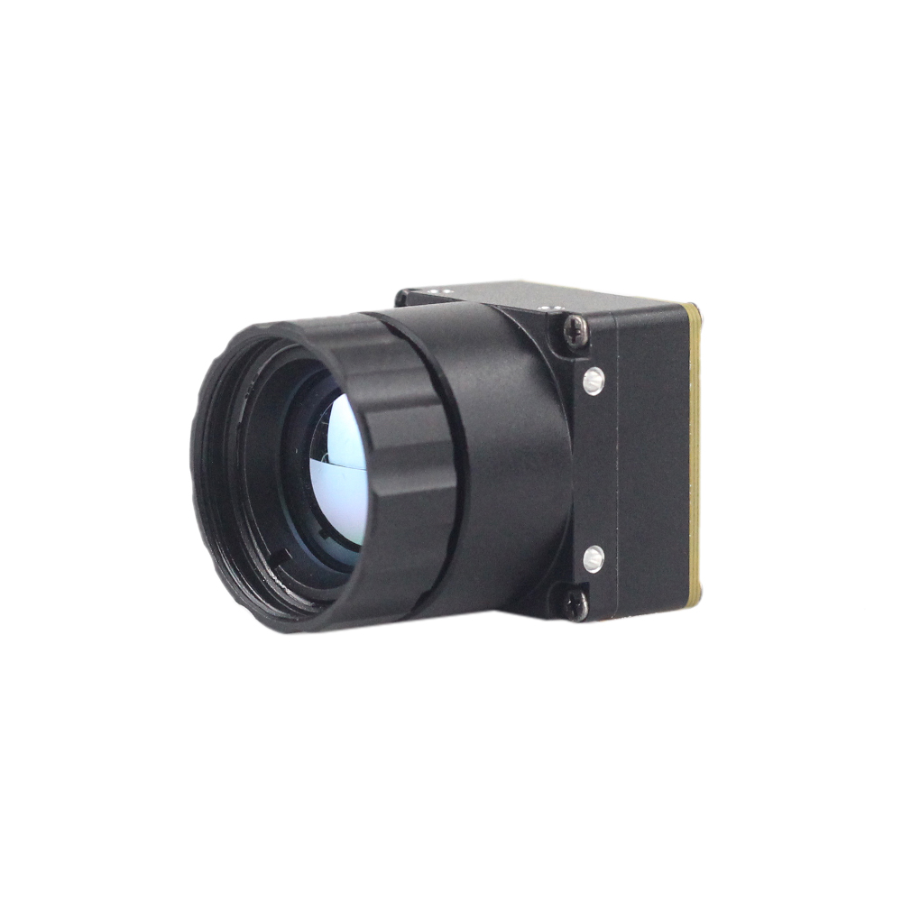
Mini 256 Uncooled LWIR Thermal Camera Module
The Mini 256 uncooled LWIR thermal camera module is engineered for ultra-compact applications requiring accurate radiometric measurement within tight SWaP constraints. Adopting high-performance infrared detectors for ultra-clear thermal imaging and accurate temperature measurement, this module captures infrared radiation and outputs a uniform thermal image with complete radiometric metadata. Designed to offer functionality similar to DJI-class platforms for detecting buried mines, concealed hazards, and fine electrical hot spots, it is well suited for micro-drones, handheld multimeters, and compact robotic chassis.
Core Technical Specifications:
| Detector Type | Uncooled VOx Microbolometer |
| Resolution & Pitch | 256 × 192 pixels (12 µm pixel pitch) |
| Spectral Range | 8 µm to 14 µm (LWIR) |
| Thermal Sensitivity (NETD) | < 40 mK to < 50 mK (@ f/1.0, 25°C) |
| Measurement Accuracy | ±2°C or ±2% of reading across industrial range |
| Electrical & Output | DVP / USB / UART Serial control; Low power consumption (< 0.8W) |
| Target Deployments | Mine detection, localized switchgear maintenance, micro-robotics |
Product Showcase 2: Mini2 640x512 9mm MIPI Thermal Imaging Camera Module For Drones
Mini2 640x512 9mm MIPI Thermal Imaging Camera Module For Drones
The uncooled infrared Mini2 640x512 9mm thermal imaging camera module for drones delivers high pixel density, low latency, and compact integration. Featuring sharp and crisp image presentation, compact dimensions, and a cost-effective architecture, this module provides native MIPI-CSI2 streaming alongside versatile configuration options for 640, 384, or 256 array designs. Fitted with a 9 mm precision-coated Germanium optic, it gives airborne inspection gimbals and automated machine vision cells the spatial clarity required to identify distant thermal anomalies on transmission towers, photovoltaic farms, and industrial perimeters.
Core Technical Specifications:
| Detector Type | Uncooled VOx Microbolometer Focal Plane Array |
| Resolution Matrix | 640 × 512 (Options for 384×288 and 256×192 pin-compatible) |
| Pixel Pitch | 12 µm |
| Optical Focal Length | 9.0 mm athermalized Germanium lens assembly |
| Interface Standards | Native 2-lane MIPI-CSI2 raw streaming, I2C command control, USB |
| Thermal Sensitivity (NETD) | < 40 mK (@ f/1.0, 25°C) |
| Core Applications | Drone inspection gimbals, in-line industrial AOI, automated sorting |
Direct Engineering Comparison
| Architectural Parameter | Mini 256 LWIR Core | Mini2 640x512 9mm MIPI Core |
|---|---|---|
| Total Pixel Count | 49,152 measurement points | 327,680 measurement points (6.6× density) |
| Native Interface | DVP / USB 2.0 / UART | Low-latency 2-Lane MIPI-CSI2 / I2C / USB |
| Optical Configuration | Compact wide-angle integrated optic | 9.0 mm precision coated Germanium optic |
| Working Range Profile | Close to medium range (0.1 m to 5 m) | Medium to long range (1.0 m to 100+ m) |
| Power Consumption | < 0.8W continuous | < 1.2W continuous |
| Mechanical Integration | Handheld enclosures, micro-gimbals, IoT probes | Airborne gimbals, robotic arms, AOI fixtures |
6. Machine Vision & Edge AI: Automated Hot-Spot Tracking and Fault Classification
Modern industrial installations are shifting from passive operator monitoring to autonomous, real-time edge processing. When integrating an industrial inspection thermal camera module into edge-AI compute clusters (such as NVIDIA Jetson Orin or embedded Linux SoCs), the software pipeline must handle both calibrated radiometric data and dynamic contrast-enhanced video streams.
Radiometric Dynamic Range vs. 8-Bit Tone Mapping
Uncooled microbolometers output 14-bit or 16-bit raw digital arrays, providing 16,384 to 65,536 discrete intensity steps per pixel. This wide dynamic range preserves sub-degree temperature measurements across scenes with wide temperature swings (e.g., from ambient room air to a 400°C steam line). However, traditional Convolutional Neural Networks (CNNs) and standard computer vision displays require 8-bit visual inputs (0 to 255 levels). Converting raw radiometric data for edge-AI processing involves two concurrent data pipelines:
- ⚙️ The 16-Bit Radiometric Telemetry Stream: Uncompressed 16-bit raw digital arrays bypass display processing and route directly into radiometric analysis routines. Edge-AI algorithms evaluate pixel values against physical thresholds, calculating minimum, maximum, and average values across dynamic Regions of Interest (ROIs) to flag anomalies (e.g., temperatures exceeding 80°C) within milliseconds.
- ⚙️ The 8-Bit Machine Vision Perception Stream: Raw data undergoes dynamic range compression using Digital Detail Enhancement (DDE) and Contrast Limited Adaptive Histogram Equalization (CLAHE). Unlike simple linear AGC—where a single hot object pushes the rest of the scene into uniform blackness—CLAHE and DDE adaptively compress broad ambient background spans while boosting local high-frequency edges. This preserves structural clarity (such as screw threads, pump edges, and pipe joints), enabling models like YOLOv8 to classify and locate components reliably.
Implementing Radiometric Extraction in OpenCV
The following Python routine illustrates how systems engineers ingest a raw 16-bit radiometric frame buffer over USB/V4L2 or MIPI-CSI2, convert raw pixel values into Celsius temperatures based on a 0.01K per LSB calibration slope, isolate anomalies above a user-defined threshold, and calculate bounding boxes for machine vision alerting:
import numpy as np
def process_thermal_radiometry(raw_16bit_frame, alert_threshold_celsius=85.0):
# Step 1: Convert raw 16-bit Digital Numbers (DN) to Kelvin (0.01K per LSB)
kelvin_array = raw_16bit_frame.astype(np.float32) * 0.01
# Step 2: Convert Kelvin array to Celsius values
celsius_array = kelvin_array - 273.15
# Step 3: Extract scene-wide statistical radiometric telemetry
max_temp = np.max(celsius_array)
min_temp = np.min(celsius_array)
avg_temp = np.mean(celsius_array)
# Step 4: Isolate pixels exceeding our critical industrial fault threshold
_, binary_mask = cv2.threshold(celsius_array, alert_threshold_celsius, 255, cv2.THRESH_BINARY)
binary_mask = binary_mask.astype(np.uint8)
# Step 5: Locate bounding contours of localized hot-spot anomalies
contours, _ = cv2.findContours(binary_mask, cv2.RETR_EXTERNAL, cv2.CHAIN_APPROX_SIMPLE)
fault_detections = []
for cnt in contours:
if cv2.contourArea(cnt) >= 4: # Filter out single-pixel transient noise
x, y, w, h = cv2.boundingRect(cnt)
peak_val = np.max(celsius_array[y:y+h, x:x+w])
fault_detections.append({
"bbox": (x, y, w, h),
"peak_temp_c": round(float(peak_val), 2)
})
return max_temp, min_temp, avg_temp, fault_detections
For more architectural perspectives on how high-sensitivity LWIR sensors enhance modern autonomous inspection and factory intelligence, review this comprehensive article on the evolution of uncooled LWIR technology.
7. Mechanical Packaging, Thermal Dissipation, and Harsh-Environment Hardening
Operating an industrial inspection thermal camera module within demanding industrial settings—such as steel mills, CNC machining centers, chemical plants, or outdoor airborne platforms—exposes the core to mechanical vibration, airborne particulates, and ambient thermal swings. Maintaining radiometric accuracy and structural reliability requires careful mechanical and thermal enclosure design.
Thermal Management in Sealed Enclosures
Because microbolometers measure microscopic temperature changes, uneven thermal gradients across the camera chassis introduce significant measurement errors. To ensure thermal stability:
- ⚙️ Direct Conductive Heat Sinking: Avoid isolating the thermal module inside dead air pockets. High-performance cores dissipate between 0.8W and 1.5W of continuous electrical power, primarily from the ADC, ROIC, and processing boards. Designers should use high-conductivity, silicone-free thermal gap fillers (with thermal conductivities greater than 3.0 W/m·K) to bridge heat directly from the module’s internal structural frame to an external aluminum enclosure.
- ⚙️ Symmetrical Thermal Loading: Never position auxiliary high-heat components—such as DC-DC switching regulators, motor H-bridges, or wireless radio transceivers—directly beside or behind one side of the microbolometer detector. Asymmetrical heating across the focal plane array generates localized baseline drift that internal NUC routines cannot fully correct, degrading image uniformity and accuracy.
- ⚙️ Optical Barrel Thermal Decoupling: Thermal expansion of the optical barrel can shift the focal plane relative to the detector surface, causing image defocusing. Using mechanically athermalized lens mounts with low-expansion Chalcogenide or invar sleeves ensures focus remains sharp across wide operational temperature envelopes (-20°C to +60°C).
Protective Viewports and Transmission Compensation
Direct exposure of delicate Germanium antireflective coatings to corrosive vapors, abrasive dust, water spray, or chemical washdowns quickly degrades the optical surface. Industrial deployments typically require enclosing the camera inside an IP67-sealed housing fitted with a protective infrared viewport:
- ✅ Infrared Optical Substrates: Conventional borosilicate or polycarbonate windows absorb LWIR radiation completely. The viewport must be fabricated from monocrystalline Germanium, Zinc Selenide (ZnSe), or Silicon, coated with a durable Diamond-Like Carbon (DLC) exterior finish to resist scratching, acid vapors, and abrasive particles.
- ✅ Transmission Attenuation Recalibration: Even high-grade DLC-coated Germanium windows absorb and reflect a portion of incident infrared energy, typically transmitting 88% to 94% of incident photons. If uncompensated, this attenuation causes the sensor to read temperatures systematically lower than actual target values. OEM software must include an adjustable optical transmission parameter (τ) to recalibrate the radiometric pipeline:
T_corrected = [ ( T_apparent - ( ( 1 - τ_window ) × T_window_ambient ) ) / τ_window ]
By entering the window's calibrated transmission factor alongside the ambient window temperature into the module's configuration registers, systems engineers can preserve ±2°C absolute radiometric accuracy even behind heavy, hermetically sealed IP67 protective enclosures.
8. Deep-Dive OEM Integration FAQ
How do I choose between 256x192 and 640x512 resolutions for industrial electrical and HVAC inspection?
Thermal camera modules often drift in fluctuating industrial environments. How is measurement stability maintained?
What are the architectural advantages of MIPI-CSI2 over USB when integrating into embedded AI vision systems?
Can an uncooled thermal camera module measure absolute surface temperature accurately through protective glass or acrylic?
📚 References & Further Reading
- Industry Standard: Precision interconnect, cabling, and ruggedized packaging hardware specifications for industrial vision: Amphenol
- Industry Standard: Specialized OEM cable harnesses and optical sub-assembly engineering: KUYANG
- Related Guide: Embedded handheld diagnostics and host driver negotiation: USB Smartphone Camera Architecture on Android
- Related Guide: Uncooled thermal video core design, ADC pipelines, and digital noise suppression: Design Principles of Uncooled Thermal Video Cores
- Related Guide: Evolution of uncooled microbolometer arrays and modern optical metrology: The Revolution of Uncooled Thermal Imaging: 5 Core Advancements