Best Industrial Inspection Thermal Camera Module: OEM Integration Guide
2026年9月30日
Best Thermal Module for Security Camera: OEM Integration & Selection Guide
2026年10月9日
Choosing the Right Thermal Camera Core for Predictive Maintenance: OEM Guide
Unplanned downtime in high-throughput industrial plants carries a catastrophic financial and operational burden, frequently exceeding tens of thousands of dollars per minute in lost output, mechanical tooling destruction, and emergency remediation efforts. Traditional condition-monitoring architectures that rely exclusively on periodic manual inspections or point-source infrared pyrometers create massive blind spots. These legacy methods systematically fail to detect distributed thermal anomalies across complex mechanical surfaces, high-density electrical cabinets, and continuous automated assembly lines. To achieve true Industry 4.0 predictive maintenance (PdM), original equipment manufacturers (OEMs), systems integrators, and automation design engineers are moving past bulky handheld imagers and static spot sensors in favor of deeply embedded, radiometric thermal camera cores. These miniature long-wave infrared (LWIR) optical engines continuously capture real-time thermodynamic gradients, exposing early-stage bearing fatigue, localized electrical phase imbalances, fluid lubrication starvation, and insulation breakdown long before catastrophic component failure occurs.
Selecting an uncooled thermal camera core for continuous automated monitoring requires balancing optical physics, digital signal integrity, edge computation overhead, and physical form factor constraints. A thermal core engineered for a lightweight aerial gimbal or an autonomous mobile robot (AMR) must operate under entirely different thermal dissipation, mass budget, and bus architecture profiles than a stationary condition sensor fixed inside an explosion-proof medium-voltage switchgear cabinet. This technical OEM guide explores the critical engineering parameters for selecting, integrating, and optimizing a thermal camera core for predictive maintenance, providing automation engineers and hardware designers with the architectural knowledge needed to build resilient, next-generation condition-monitoring nodes.
Table of Contents
- 👉 The PdM Paradigm Shift: Continuous Area Monitoring vs. Point Pyrometers
- 👉 Key OEM Sensor Parameters: Resolution, NETD, and Frame Rate
- 👉 Data Bus Architectures & Signal Processing: MIPI, USB, and Edge AI
- 👉 Optical Engineering: Instantaneous Field of View (IFOV) and Focal Length Matching
- 👉 Product Showcase: Mini 640 Uncooled LWIR USB Thermal Module
- 👉 Product Showcase: Mini2 MIPI 640/384/256 Thermal Module
- 👉 OEM Core Comparison: Benchmarking Mini USB vs. Mini2 MIPI Modules
- 👉 Overcoming Integration Bottlenecks: Thermal Drift, NUC, and Mechanical Enclosures
- 👉 Application Architectures: Switchgear, Turbomachinery, and Mobile Robotics
- 👉 Engineering Deep-Dive FAQ
The PdM Paradigm Shift: Continuous Area Monitoring vs. Point Pyrometers
Modern predictive maintenance strategies rely on capturing thermodynamic drift well before physical mechanisms suffer permanent mechanical or dielectric failure. When electromechanical components experience micro-fractures, lubrication breakdown, chemical contamination, or high-resistance electrical connections, they dissipate kinetic and electrical energy outward in the form of localized heat. Identifying this emitted thermal energy during early operational degradation is the single most reliable way to prevent catastrophic secondary damage across heavy industrial machinery.
Historically, industrial facilities monitored operational temperatures using single-point infrared pyrometers or manual thermography inspection walkdowns using handheld cameras. Both methodologies introduce major operational and technical vulnerabilities into modern continuous manufacturing lines. A non-imaging infrared pyrometer optical system averages all emitted infrared flux over a geometric target area defined by its distance-to-spot ratio. If an overheating electrical lug on an automation control panel or a micro-crack on a high-speed roller bearing occupies only a tiny fraction of that measurement spot, the pyrometer averages the defect's extreme temperature with the cooler surrounding ambient background. The resulting measurement underreports the anomaly, leaving critical thermal runaways undetected until direct failure occurs.
Similarly, manual walkdowns using handheld thermal cameras capture machine health only at arbitrary, discontinuous points in time. Industrial machinery experiences complex, dynamic duty cycles. If severe peak thermal stresses manifest during specific high-torque mechanical states, transient electrical surges, or off-shift production cycles when thermographers are absent, developing defects remain unrecorded until complete system breakdown. Furthermore, routing personnel into energized, high-voltage substations or explosive chemical processing environments presents profound safety, arc-flash, and liability risks.
Integrating an uncooled thermal camera core for predictive maintenance directly into industrial machinery, production cells, or autonomous inspection robots fundamentally changes condition monitoring. Rather than taking intermittent spot checks, an uncooled microbolometer continuously records long-wave infrared radiation—typically within the 8 to 14 micrometer spectral range—across an entire spatial pixel matrix. Every individual pixel on the sensor array functions as an independent, calibrated radiometric thermometer. By continuously streaming radiometric matrix frames into embedded processing units, OEM systems run automated real-time diagnostics, calculating spatial temperature differentials, rate-of-rise metrics, and multi-zone threshold evaluations across structural machinery boundaries.
Key OEM Sensor Parameters: Resolution, NETD, and Frame Rate
Specifying an embedded thermal camera engine requires a balanced evaluation of sensor physics to meet application-specific demands without unnecessarily inflating bill-of-materials costs, compute loads, or mechanical footprint constraints. System designers must carefully evaluate spatial resolution, thermal sensitivity, and temporal sampling rates to ensure the chosen core matches both the mechanical realities of the machine and the mathematical requirements of edge analytics.
1. Spatial Resolution and Array Density
The native pixel resolution of an infrared focal plane array (FPA) determines its spatial measurement density and optical field of view. Lower-resolution arrays, such as 256×192 or 384×288 detectors, are well suited for localized, fixed-geometry installations where the region of interest is tightly restricted—such as monitoring an isolated terminal junction block or an individual small pump seal. However, for complex industrial assemblies or wider inspection fields, higher spatial resolution is indispensable.
A native 640×512 resolution core delivers 327,680 discrete temperature points per frame. This high pixel density enables an OEM design to monitor an entire multi-stage motor-pump assembly, a wide bank of high-voltage circuit breakers, or complex industrial mechanical linkages with a single sensor head. Crucially, high array density ensures that small, critical components—such as individual terminal screws or localized bearing races—subtend enough pixels at safe working distances to yield mathematically accurate absolute temperature readings rather than blended approximations.
2. Thermal Sensitivity (NETD)
Noise Equivalent Temperature Difference (NETD) is the primary metric defining an infrared detector's thermal sensitivity. Expressed in millikelvins (mK), NETD quantifies the minimum temperature differential the core can resolve before detector noise obscures the measurement. The lower the millikelvin rating, the cleaner and more sensitive the thermal signal.
While coarse sensors rated at 50mK or higher can detect gross failures—such as a totally collapsed bearing assembly or an uncoupled phase conductor running hot—they lack the sensitivity needed to capture subtle thermodynamic clues. High-performance cores delivering sensitivities of less than 40mK or 30mK are necessary for detecting early mechanical friction, slight subsurface insulation degradation, micro-fluidic blockages, and low-amplitude harmonic heating. Lower NETD values directly translate into a higher signal-to-noise ratio, stabilizing automated edge detection algorithms and preventing false alarm trips caused by electrical interference in industrial environments.
3. Frame Rate: 25Hz/30Hz/50Hz vs. Export-Controlled 9Hz
The frame rate of a thermal camera core directly affects its dynamic measurement accuracy and global procurement logistics. Cores operating at frame rates below 9Hz are exempt from strict dual-use Wassenaar Arrangement export controls. This exemption significantly simplifies international component shipping, customs clearances, and multi-regional supply chain management for global OEMs. However, a 9Hz temporal refresh rate is inadequate for tracking fast-moving rotary components, dynamic robotic arms, pan-tilt gimbal platforms, or continuous high-speed web handling lines, where motion blur ruins pixel-level radiometry.
Cores operating at smooth industrial frame rates of 25Hz, 30Hz, or 50Hz provide the rapid temporal sampling needed to resolve fast-moving thermal events. Smooth frame rates eliminate spatial smearing, ensuring that each microbolometer pixel reaches steady-state radiometric integration even when the sensor is moving on an autonomous robotic cart or tracking dynamic cyclical mechanical processes.
Data Bus Architectures & Signal Processing: MIPI, USB, and Edge AI
Selecting an OEM thermal camera core requires aligning the sensor's physical and electrical data interface with the host processing architecture. Industrial engineers must choose between low-level embedded hardware buses and standardized, host-driven serial interfaces based on latency, cabling distance, compute budgets, and enclosure limitations.
MIPI-CSI2: Ultra-Low-Latency Embedded Interfacing
For deeply embedded edge designs, weight-constrained robotic platforms, and aerial payloads, the Mobile Industry Processor Interface Camera Serial Interface 2 (MIPI-CSI2) represents the premier physical layer standard. MIPI-CSI2 routes uncompressed, raw digital radiometric stream data directly into the host processor's Image Signal Processor (ISP) and memory subsystem using Direct Memory Access (DMA). This direct board-level connection bypasses the protocol translation, framing overhead, serialization steps, and OS driver latencies typical of USB bridges.
Because MIPI engines interface directly with system-on-chip architectures—such as NVIDIA Jetson, NXP i.MX8, or Rockchip platforms—they consume minimal host CPU cycles for packet handling. This allows the host processor to dedicate its computational budget entirely to complex thermal analytics and machine vision. System architects looking to integrate advanced machine vision models can review the detailed AI thermal camera selection framework to evaluate edge bandwidth trade-offs alongside neural network inference latencies. The primary trade-off with MIPI is trace length: high-speed MIPI signals are typically restricted to short flex-PCB runs under 15 to 20 centimeters without active, power-consuming serialization hardware.
USB 2.0 / Type-C (UVC + Radiometric Telemetry)
For applications where the sensor head must sit several meters away from the primary compute module, or where system engineers need rapid development turnarounds, USB interfaces provide unmatched integration speed. USB-enabled cores leverage the universal USB Video Class (UVC) standard, enabling immediate streaming of false-color visual thermal frames across native Linux, Windows, and Android runtimes without custom kernel drivers. Radiometric temperature metadata is typically transmitted concurrently across a secondary virtual COM port or a dedicated vendor endpoint, giving application software direct, per-pixel temperature arrays.
USB simplifies retrofitting predictive maintenance capabilities onto existing industrial machines, test benches, and processing enclosures. To ensure reliable signal integrity, ruggedized data cabling, and continuous EMC shielding across challenging industrial operating environments, design teams frequently incorporate mission-critical connection solutions from TE Connectivity to protect physical links from electromagnetic noise and factory floor vibration.
Edge AI Processing Architectures
Rather than continuously streaming massive volumes of high-bandwidth raw radiometric video across industrial wireless or fieldbus networks to centralized server rooms, modern Industry 4.0 architectures execute inference models directly at the machine edge. Combining embedded thermal cores with compact AI computing hardware provides two primary functional advantages:
- ✅ Dynamic Target and Region-of-Interest (ROI) Tracking: Convolutional neural networks identify and isolate specific components—such as bearing caps, busbar splices, gearbox seals, and cooling fins—within the thermal field of view. The system dynamically measures temperatures on these target assets while filtering out non-critical background thermal swings, hot exhaust vents, and ambient structural shifts.
- ✅ Intelligent Anomaly Filtering: On-device inference algorithms evaluate localized thermal trends in real time, distinguishing between normal baseline heat increases (such as an induction motor ramping up under higher torque) and abnormal thermodynamic runaways caused by mechanical friction, electrical degradation, or phase imbalances.
Optical Engineering: Instantaneous Field of View (IFOV) and Focal Length Matching
Thermal optical systems cannot rely on standard borosilicate optical glass, which is opaque to long-wave infrared wavelengths. Instead, thermal lenses require specialized, precision-machined elements fabricated from Germanium (Ge), Chalcogenide glass alloys, or high-purity Silicon. Selecting the proper lens focal length requires calculating the physical relationship between sensor pixel pitch, target component dimensions, stand-off distances, and optical dispersion physics.
The fundamental metric for optical design is the Instantaneous Field of View (IFOV), which describes the angular cone seen by an individual microbolometer pixel. The IFOV, expressed in milliradians (mrad), is calculated using the following formula:
IFOV (mrad) = [Pixel Pitch (microns) / Focal Length (mm)]
Multiplying the calculated IFOV by the operating distance between the sensor and the monitored target yields the projected physical spot size represented by a single pixel. However, due to optical diffraction, optical aberrations, and atmospheric scattering, a target that fills only a single pixel will not provide an accurate temperature reading. Optical physics dictates that the physical target must completely cover a minimum measurement spot of at least 3×3 pixels—and ideally 4×4 pixels—to ensure optical energy fills the microbolometer detector without background attenuation. This corrected threshold is known as the Measurement Field of View (MFOV).
| Focal Length | Typical FOV (640 Core) | IFOV (12µm Pitch) | Min Accurate Target Size @ 5m (3×3 MFOV) | Primary Industrial Application |
|---|---|---|---|---|
| 5.0 mm | ~88° × 70° | 2.40 mrad | 36.0 mm | Internal switchgear cabinets, tight machine frames, bus ducts |
| 9.1 mm | ~48° × 38° | 1.32 mrad | 19.8 mm | General motor-pump skids, short-range robotic inspection payloads |
| 18.0 mm | ~24° × 19° | 0.67 mrad | 10.0 mm | Medium-range factory monitoring, conveyor bearing diagnostics |
| 35.0 mm | ~12.5° × 10° | 0.34 mrad | 5.1 mm | Outdoor electrical substations, overhead cranes, high-bay monitors |
| 50.0 mm - 150.0 mm | Sub-9° Narrow | < 0.24 mrad | < 3.6 mm | Long-range utility infrastructure, flare stacks, high-voltage lines |
Choosing between wide-angle and narrow-telephoto optics involves a fundamental mechanical trade-off. Wide-angle lenses (5mm to 9mm) provide broad spatial coverage across close-proximity equipment, but their large IFOV limits their ability to resolve small thermal details from a distance. Conversely, telephoto lenses (35mm to 150mm) can resolve small, millimeter-scale thermal anomalies from tens of meters away, keeping sensors and personnel safely outside high-voltage arc-flash zones. However, telephoto lenses require larger germanium optical elements, which increases both the overall payload weight and optical hardware costs.
Product Showcase: Mini 640 Uncooled LWIR USB Thermal Module
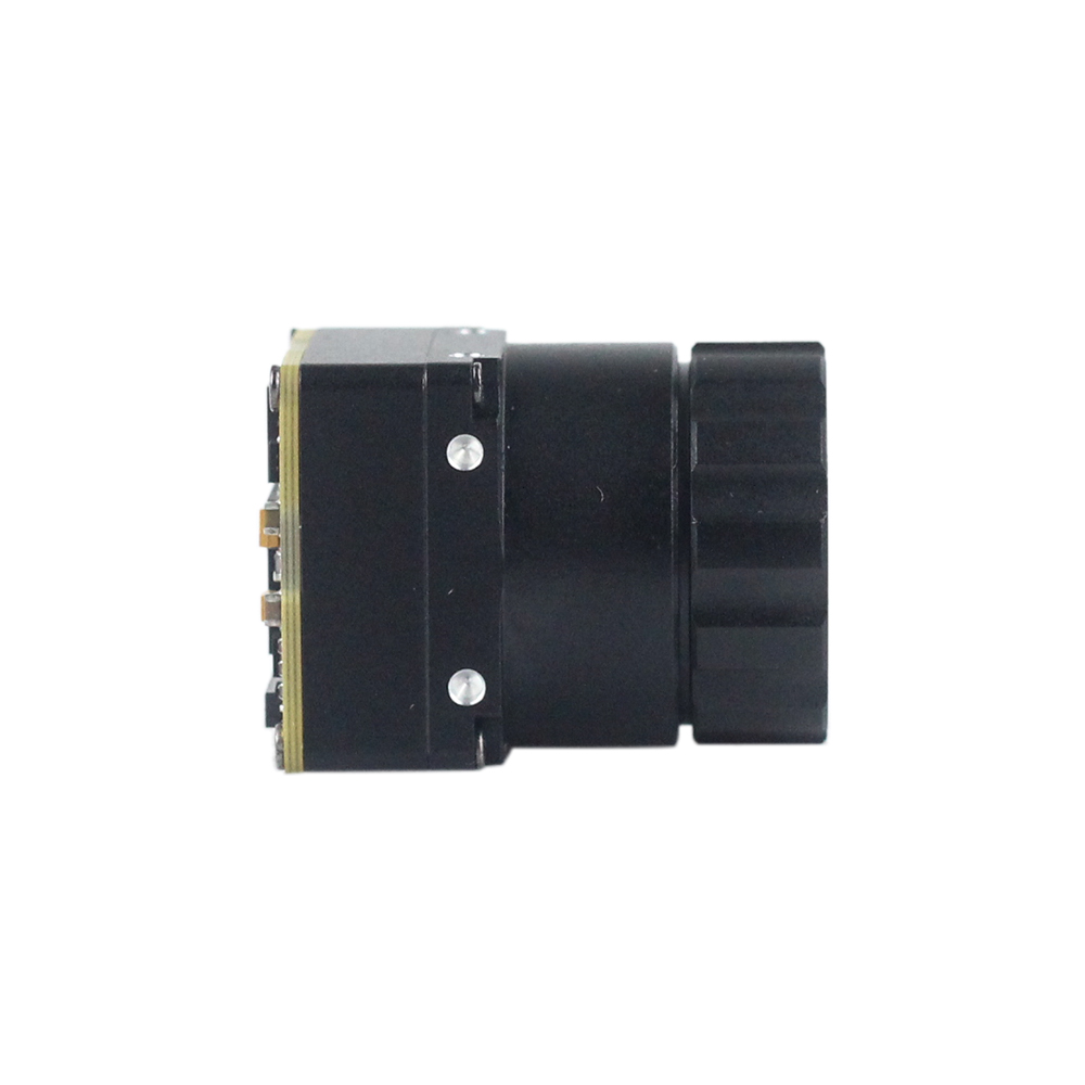
The Mini 640 Uncooled LWIR USB Thermal Imaging Camera Core Module is engineered for high-performance industrial predictive maintenance, system prototyping, and embedded monitoring applications. Featuring an ultra-compact outer form factor of just 21mm by 21mm, this lightweight core delivers high-definition radiometric thermal imaging in a package designed for space-constrained industrial installations. The core provides crisp image quality, stable radiometric performance, and exceptional environmental adaptability across harsh factory environments.

With its native 640×512 resolution (640×480 resolution optional), this module packs 327,680 measurement pixels into a 21mm housing, allowing OEM engineers to capture minute temperature gradients across large machinery surfaces. The module interfaces over standard USB, functioning as a plug-and-play UVC video source while simultaneously delivering uncompressed radiometric data arrays across a secondary virtual telemetry interface. This simplifies integration into industrial PCs, test fixtures, and machine vision setups.
A major design strength of the Mini 640 is its broad optical compatibility. The core supports a comprehensive optical line-up with interchangeable focal lengths: 5mm, 9mm, 13mm, 18mm, 35mm, 50mm, 75mm, 100mm, and 150mm. This wide focal range gives systems engineers the flexibility to configure the module for close-proximity switchgear cabinets using wide optics or long-range utility monitoring using telephoto lenses.
View Product Details & Pricing ➔
Product Showcase: Mini2 MIPI 640/384/256 Thermal Module
The Mini2 Uncooled Infrared MIPI Thermal Imaging Camera Module is built for size-, weight-, and power-constrained (SWaP) applications, including airborne drone gimbals, compact autonomous mobile robotics, and embedded edge devices. Delivering crisp thermal image presentation, high spatial sensitivity, and a lightweight footprint at a competitive price point, the Mini2 module streams raw radiometric data directly to host processors over a native MIPI-CSI2 connection.

The Mini2 is available in multiple native resolution options—including high-resolution 640×512, balanced 384×288, and cost-effective 256×192 arrays. This range allows OEM design teams to standardize on a single electrical architecture across different product tiers. The standard 9mm thermal lens configuration provides a balanced field of view optimized for mobile inspection platforms, automated robotic surveillance carts, and unmanned aerial monitoring systems.
By routing uncompressed radiometric video directly across MIPI-CSI2 lanes into the host processor's DMA pipeline, the Mini2 achieves ultra-low transmission latency with minimal CPU overhead. This makes it an ideal platform for running real-time edge AI models, such as automated target tracking, spatial temperature profiling, and instant anomaly triggering on embedded systems like the NVIDIA Jetson platform.
View Product Details & Pricing ➔
OEM Core Comparison: Benchmarking Mini USB vs. Mini2 MIPI Modules
Engineers can explore the wider portfolio within the OEM thermal core catalog to evaluate hardware options across varied industrial form factors. The table below provides a direct architectural comparison between the Mini 640 USB module and the Mini2 MIPI core, helping engineering teams choose the right hardware architecture for their predictive maintenance platform:
| Hardware Feature | Mini 640 Uncooled LWIR USB Core | Mini2 640/384/256 MIPI Core |
|---|---|---|
| Native Array Resolution | 640×512 (640×480 optional) | Configurable: 640×512 / 384×288 / 256×192 |
| Form Factor Dimensions | 21mm × 21mm ultra-compact block | Sub-miniature, low-profile footprint |
| Lens Options (Focal Length) | Broad line-up: 5 / 9 / 13 / 18 / 35 / 50 / 75 / 100 / 150mm | Optimized 9mm standard configuration |
| Primary Communication Bus | USB 2.0 / USB Type-C (UVC Video + Telemetry) | MIPI-CSI2 (Direct Memory Access via ISP) |
| Data Latency Profile | Standard host-driven latency (15–30 ms) | Ultra-low direct pipeline latency (< 5 ms) |
| Driver Integration Level | Universal UVC driver stack; rapid cross-platform deployment | Board support package (BSP) driver integration required |
| Ideal Application Space | Fixed machine monitoring, IPCs, test benches, retrofit pods | Inspection drones, micro-gimbals, battery-powered robotics |
Overcoming Integration Bottlenecks: Thermal Drift, NUC, and Mechanical Enclosures
Integrating an uncooled microbolometer sensor into heavy industrial machinery introduces real-world thermal, optical, and mechanical challenges. Unlike active visible-light image sensors, uncooled thermal detectors absorb ambient radiation directly, altering their internal electrical resistance. As a result, ambient thermal swings and localized internal electronics heat will distort baseline radiometric values if not properly managed.
1. Thermal Drift and Non-Uniformity Correction (NUC) Management
As an industrial camera engine warms up during normal operation, internal electronic components generate heat that conducts into the optical barrel and sensor housing. This localized heating causes non-uniform baseline signal drift across the microbolometer array. To maintain high radiometric accuracy, embedded cores use Non-Uniformity Correction (NUC) algorithms:
- ⚙️ Mechanical Shutter Calibration: Most cores use a miniature mechanical solenoid shutter that briefly drops a uniform, opaque blade in front of the detector array for approximately 200 milliseconds. This momentary event provides a flat, single-temperature reference frame, allowing the internal processor to calculate updated per-pixel offset correction coefficients. However, this shutter event momentarily pauses the video feed, which may be problematic for high-speed dynamic tracking systems.
- ⚙️ Shutterless Algorithmic Correction: For real-time applications where a 200ms frame freeze is unacceptable, high-performance cores use shutterless correction engines. These systems use arrays of high-precision internal thermistors positioned across the lens barrel, detector substrate, and processing board. Real-time mathematical models process these temperature inputs against extensive multi-point lookup tables, adjusting per-pixel gain and offset continuously without interrupting the radiometric stream.
2. Optical Protective Windows and Material Transmittance
Deploying a sensitive thermal core into rugged manufacturing environments requires packaging it inside a protective IP67, IP68, or NEMA 4X enclosure. Standard viewing windows made of acrylic, borosilicate glass, or polycarbonate are opaque to the 8–14 μm LWIR spectrum and cannot be used. Instead, system designers must select dedicated infrared optical materials:
- ⚙️ Germanium (Ge): The industry standard for ruggedness, offering high mechanical surface hardness and exceptional LWIR transmission efficiency. However, Germanium experiences thermal runaway at elevated operating temperatures (typically above 70°C), where its internal transmission drops significantly.
- ⚙️ Zinc Selenide (ZnSe): Provides broad spectral transmission spanning visible through long-wave infrared wavelengths, making it well-suited for dual-spectrum visible-thermal systems. However, ZnSe is mechanically softer than Germanium and requires protective antireflective coatings in abrasive industrial settings.
- ⚙️ Silicon (Si): A lightweight, cost-effective window material ideal for high-volume deployments, though it delivers slightly lower overall transmission efficiency across long wavelengths.
Every protective window introduces a measurable degree of infrared absorption and surface reflection. The window's transmission coefficient (typically between 88% and 94%) must be factored directly into the core's radiometric calculation engine. Failing to calibrate for window attenuation will cause the system to consistently underreport absolute asset temperatures.
Application Architectures: Switchgear, Turbomachinery, and Mobile Robotics
Applying embedded thermal imaging cores across diverse industrial environments requires application-specific mounting geometries, data pathways, and optical selections tailored to the operating conditions.
1. Continuous High-Voltage Switchgear and Busbar Monitoring
Arc-flash hazards make opening energized medium- and high-voltage switchgear doors to perform manual thermal checks exceptionally dangerous for maintenance personnel. By mounting miniature thermal camera cores—such as the 21mm × 21mm Mini 640 USB module fitted with wide-angle 5mm optics—permanently inside isolated breaker compartments, facilities achieve continuous, hands-free thermographic visibility.
These fixed cores continuously inspect high-risk connection points, including busbar splices, cable terminations, and circuit breaker stabs. When electrical connections experience mechanical loosening, surface oxidation, or harmonic distortion, the resulting high-resistance joints generate localized heat. The embedded core flags these temperature rises the moment current-induced thermal stress begins, dispatching automated alerts over industrial networks long before an explosive arc-flash event occurs.
2. Heavy Rotating Turbomachinery and Critical Bearing Assemblies
Continuous thermal monitoring across industrial turbomachinery, induction motor bearings, and high-load pillow blocks catches early lubrication breakdown and mechanical wear. When lubricating grease degrades, leaks past seals, or suffers particulate contamination, metal-on-metal friction generates localized heat before high-frequency mechanical vibration levels breach alarm thresholds.
Mounting an embedded uncooled core directed at the bearing housing provides an immediate, continuous thermal gradient profile. By pairing real-time radiometric telemetry with traditional vibration spectral analysis, reliability systems gain dual-modality fault verification. This integrated approach confirms emerging mechanical failures while eliminating false alarms triggered by ambient noise or harmless process load variations.
3. Mobile Robotic and Autonomous Aerial Infrastructure Audits
For large-scale industrial complexes—such as utility solar farms, sprawling petrochemical plants, and overhead transmission line corridors—fixed sensor installations can be cost-prohibitive. In these environments, integrating lightweight, low-power thermal cores into autonomous robotic systems and aerial inspection platforms provides an ideal predictive maintenance solution.
In autonomous UAV applications, systems such as those engineered by OBSETECH show how high-resolution LWIR cores integrate into balanced aerial gimbals, combining live radiometric tracking with autonomous flight planning. System designers can view real-world aerial implementations in this drone thermal video integration overview to see how lightweight aerial gimbals maintain image stabilization and stream radiometric telemetry during mobile inspections.
Engineering Deep-Dive FAQ
How reliable is a thermal camera core for detecting early bearing failures?
Does 24/7 predictive maintenance require an enterprise-level budget?
How does Edge AI enhance thermal cores in industrial environments?
📚 References & Further Reading
- ⚙️ Industry Standard: Industrial connectivity and harsh-environment sensor hardware by TE Connectivity
- ⚙️ Industry Standard: Advanced robotic aerial inspection and drone integration architectures by OBSETECH
- ⚙️ Related Guide: AI-Powered Thermal Camera Selection Framework
- ⚙️ Related Guide: Explore the Full Industrial Thermal Core Catalog
- ⚙️ Related Guide: Drone-Mounted Thermal Imaging Camera Module Integration Video