وحدة التصوير الحراري عالية الأداء: تكامل الذكاء الاصطناعي الطرفي وحلول المصنّع الأصلي للطائرات بدون طيار
12 أغسطس 2026
دليل اختيار وحدة التصوير الحراري عالية الأداء لمصنعي المعدات الأصلية والطائرات بدون طيار
عند هندسة أنظمة الروبوتات المستقلة، أو المراقبة الجوية، أو الصيانة التنبؤية الصناعية، فإن دمج وحدة تصوير حراري من الفئة المؤسسية وحدة التصوير الحراري ليس مجرد ميزة لطيفة للتباهي بها - إنه خيار معماري أساسي. يجب أن تقدم الأنظمة الكهروضوئية الحديثة بيانات حرارية واضحة عبر البيئات الجوية القاسية، والدخان الكثيف، والضباب، وظروف انعدام الضوء. ولكن ها هي الحقيقة: إن ضغط نواة الأشعة تحت الحمراء طويلة الموجة غير المبردة في محاور الطائرات بدون طيار محدودة المساحة، أو معدات الفحص المحمولة، أو حمولات الأمان الآلية يعني موازنة الأداء البصري، والحساسية الحرارية، وزمن انتقال المعالجة، والبصمة المادية. كمهندسي أنظمة بصرية، نقوم باستمرار بمقايضات صعبة - مثل موازنة تباعد البكسل مقابل فتحة العدسة، أو اختيار لوحات معالجة ASIC خفيفة الوزن على منصات SDK الإشعاعية كاملة الميزات لإبقاء المشروع على المسار الصحيح.
الحصول على كفاءة تصوير حراري حقيقية يتلخص في تحسين SWaP-C (الحجم، الوزن، الطاقة، والتكلفة) دون تدمير أداء الكاشف. سواء كنت تبني طائرات بدون طيار دفاعية مع التعرف التلقائي على الأهداف أو تقوم بإعداد مستشعرات حرارية لإنترنت الأشياء الصناعي لمراقبة المحطات الفرعية على مدار الساعة طوال أيام الأسبوع، فإن اختيار النواة الصحيحة يتطلب فهمًا قويًا لفيزياء الميكروبولومتر، ومعايير الواجهة (RTSP عبر IP مقابل CVBS التناظري منخفض زمن الانتقال للغاية)، وخوارزميات تصحيح عدم الانتظام (NUC). يفصل دليل الاختيار هذا المبادئ الأساسية، وسير العمل الهندسي، والمواصفات الواقعية التي تحتاجها لدمج محركات كاميرات التصوير الحراري OEM في إعدادات الأجهزة المخصصة.
جدول المحتويات
- 👉 أساسيات وحدة التصوير الحراري ذات الطور الهندسي
- 👉 استراتيجية تحسين SWaP-C للحمولات المستقلة والطائرات بدون طيار
- 👉 هندسة واجهة الفيديو الديناميكية: RJ45 RTSP مقابل CVBS التناظري
- 👉 قياس أداء منتجات OEM الشامل ومحرك المواصفات
- 👉 المعايرة البصرية، وتصحيح عدم الانتظام (NUC)، ومقاييس قياس درجة الحرارة
- 👉 دليل الأسئلة الشائعة التقنية الصناعية
أساسيات وحدة التصوير الحراري ذات الطور الهندسي
تختلف وحدة التصوير باستخدام تقنية الأشعة تحت الحمراء طويلة الموجة (LWIR) تعمل عن طريق التقاط الإشعاع الحراري المنبعث من الأجسام السطحية ضمن النطاق الطيفي من 8 ميكرومتر إلى 14 ميكرومتر. على عكس المستشعرات البصرية القياسية التي تحتاج إلى ضوء محيط، تكتشف مصفوفة الميكروبولومتر الحراري غير المبردة اختلافات إشعاع الجسم الأسود وتحول الحرارة الحركية الخام إلى خرائط حرارية رقمية واضحة. هذا الاستقلال عن الضوء المرئي يجعل محرك كاميرا الأشعة تحت الحمراء لا غنى عنه للعمليات المظلمة، ومهام البحث والإنقاذ، وفحص الخزانات الكهربائية، وإعدادات الكشف المبكر عن الحرائق.
لفهم كيف تتحول الحرارة إلى تغذية فيديو قابلة للاستخدام أو شبكة درجة حرارة إشعاعية، دعنا نمر عبر خط أنابيب الأجهزة خطوة بخطوة:
- ⚙️ بصريات الجرمانيوم / الكالكوجينيد: الزجاج البصري القياسي يحجب ضوء الأشعة تحت الحمراء تمامًا. لذا، تعتمد نواة الأشعة تحت الحمراء على عدسات الجرمانيوم أو الكالكوجينيد المطلية بمضاد الانعكاس (AR) والمصممة لتمرير فوتونات 8-14 ميكرومتر مع قمع التشوهات البصرية.
- ⚙️ مصفوفة كاشف الميكروبولومتر غير المبرد: يمر إشعاع الأشعة تحت الحمراء عبر العدسة ويصطدم بمصفوفة ميكروبولومتر صغيرة معلقة مصنوعة من مواد حساسة للحرارة. عندما تقوم الفوتونات بتسخين الجسور المعلقة، تتغير مقاومتها الكهربائية مباشرة بناءً على معامل درجة حرارة المقاومة (TCR) للمادة.
- ⚙️ دائرة القراءة المتكاملة (ROIC): أسفل مصفوفة الميكروبولومتر مباشرة توجد دائرة CMOS المتكاملة للقراءة (ROIC). تقوم ROIC بأخذ عينات من تغيرات المقاومة بكسلًا تلو الآخر، محولةً التغيرات الكهربائية الدقيقة إلى قيم رقمية نظيفة.
- ⚙️ محرك المعالجة المدمج (ASIC/FPGA): تُغذى القيم الرقمية إلى معالج مدمج مخصص. هنا، تعمل خوارزميات تصحيح عدم الانتظام (NUC)، واستبدال البكسلات التالفة (BPR)، وتصفية الضوضاء، والنطاق الديناميكي في الزمن الحقيقي لإنتاج فيديو نظيف عالي التباين أو مقاطع حرارية معايرة لدرجة الحرارة.
- ⚙️ الواجهة الخلفية متعددة البروتوكولات: أخيرًا، تقوم الواجهة الخلفية بتجميع الفيديو أو القياسات الإشعاعية الحرارية في مخرجات قياسية—مثل التغذية التناظرية CVBS عديمة التأخير أو تدفقات RTSP/ONVIF القائمة على IP عبر إيثرنت RJ45.
فيزياء الكاشف الأساسي: VOx مقابل a-Si
في قلب أي محرك حراري OEM حديث توجد مقاومات الأغشية الرقيقة من أكسيد الفاناديوم (VOx) أو السيليكون غير المتبلور (a-Si) المثبتة على دائرة ROIC سيليكونية دقيقة التصنيع. الاختيار بين هاتين المادتين هو أحد أكبر القرارات التي ستتخذها عند اختيار العتاد:
- ✅ أكسيد الفاناديوم (VOx): توفر ميكروبولومترات VOx معامل مقاومة حرارية (TCR) أعلى بكثير. بعبارات بسيطة: حساسية كهربائية أعلى، وضوضاء أقل، واستقرار قوي طويل الأمد. VOx هو المعيار الذهبي للفحص الصناعي عالي الدقة، والحمولات الدفاعية، ومعدات الطائرات بدون طيار المؤسسية حيث يكون التقاط فروق درجات الحرارة دون الدرجة الواحدة أمرًا مهمًا.
- ✅ السيليكون غير المتبلور (a-Si): يمنح السيليكون غير المتبلور استجابة مكانية موحدة وقوية عبر المستوى البؤري ويبقي تكاليف الإنتاج منخفضة في عمليات التشغيل عالية الحجم. بينما تعمل نوى a-Si عمومًا بحساسية أقل قليلاً من VOx، فإن نقطة سعرها المنخفضة تجعلها مثالية لأنظمة الأمن التجارية وأدوات المستهلك الاقتصادية.
الدقة المكانية وديناميكيات تباعد البكسل
تملي دقة المصفوفة التفاصيل المكانية، ومجال الرؤية (iFOV)، ومدى الكشف والتعرف والتمييز (DRI) المكاني بناءً على معايير جونسون القياسية:
| تنسيق المصفوفة | إجمالي عدد البكسلات | سيناريوهات النشر المثلى | التأثير البصري وتأثير SWaP |
|---|---|---|---|
| مصفوفة 384×288 | 110,592 بكسل | الطائرات بدون طيار الصغيرة، الأدوات المحمولة، مراقبة المحيط قصيرة المدى | بصمة خفيفة الوزن، استهلاك طاقة ضئيل، خيارات عدسات مدمجة |
| مصفوفة 640×512 | 327,680 بكسل | طائرات البحث والإنقاذ المؤسسية بدون طيار، الحمولات التكتيكية عالية الارتفاع، فحص محطات الطاقة | ما يقرب من 3 أضعاف عدد البكسلات، مسافات DRI ممتدة، رؤية أفقية أوسع |
إلى جانب دقة المصفوفة، يحدد تباعد البكسل—المقاس بالميكرومتر (μm)—المسافة من المركز إلى المركز بين عناصر الكاشف المتجاورة. كان الانتقال من مستشعرات $17\mu m$ القديمة إلى ميكروبولومترات $12\mu m$ المتقدمة مكسبًا هائلاً لتصاميم حمولات الطيران. التخفيض إلى $12\mu m$ يقلل الطول البؤري البصري المطلوب لنفس عامل التكبير. هذا يعني أنه يمكنك تقليص قطر العدسة وكتلتها بنسبة 30% إلى 40% دون فقدان أداء المدى. للحصول على تفصيل أعمق حول دمج النوى عبر وحدات الاستشعار المتعددة، اقرأ دليل دمج وحدة الكاميرا الحرارية متعددة الوظائف LTC.
الحساسية الحرارية (NETD) ومعدلات تحديث الإطار
هناك مواصفتان رئيسيتان تحددان مدى جودة فيديو المخرجات في ظل ظروف المجال الحقيقية:
- ⚙️ فرق درجة الحرارة المكافئ للضوضاء (NETD): تقاس بالميلي كلفن (mK)، وتحدد NETD أصغر تغير في درجة الحرارة يمكن للمستشعر التقاطه فوق ضوضاء الكاشف الأساسية. الوحدة المصنفة عند $\le 30\text{ mK}$ أو $\le 40\text{ mK}$ ستكشف الحدود الحرارية الدقيقة—مثل عزل المباني الرطب أو الآثار الرفيعة التي تسخن على لوحة الدوائر المطبوعة—بشكل أفضل بكثير من النواة الاقتصادية المصنفة عند $\ge 50\text{ mK}$.
- ⚙️ Frame Refresh Rates (25Hz / 30Hz / 50Hz / 60Hz): High frame rates are non-negotiable for stabilizing aerial gimbals and tracking fast-moving targets. While 9Hz cores bypass strict Wassenaar export rules, serious tactical and tracking applications require $\ge 30\text{Hz}$ or $50\text{Hz}$ to eliminate motion blur during fast drone turns.
2. SWaP-C Optimization Strategy for UAV & Autonomous Payloads
When you're fitting an OEM thermal camera engine into a drone, autonomous robot, or handheld rig, every gram and milliwatt counts. Extra mass cuts flight time down immediately, while excess heat build-up inside a sealed gimbal enclosure degrades detector sensitivity over time.
Here's how experienced payload engineers manage SWaP-C across hardware builds:
| SWaP-C Constraint | Primary Engineering Bottleneck | Architectural Solution Strategy |
|---|---|---|
| Physical Size & Mass | Heavy optic glass and bulky chassis ruin gimbal tuning and cut airframe flight time. | Use 12µm VOx detector arrays; pick CNC magnesium-aluminum or carbon-composite housing. |
| Electrical Power Draw | High power draw eats main flight batteries and causes internal self-heating. | Deploy custom low-power Application-Specific Integrated Circuits (ASICs) (<1.5W power draw). |
| Optical Efficiency | Narrow aperture lenses cut photon collection, degrading overall sensitivity. | Integrate fast F/1.0 to F/1.2 Germanium lenses with hard carbon protective coatings. |
| Edge AI Processing | Streaming raw video to ground stations adds latency and drops under interference. | Mount lightweight AI acceleration chips right onto the thermal board for local object recognition. |
Power Dissipation & Thermal Balance Mechanics
Uncooled microbolometer arrays react quickly to environmental heat shifts. Conductive or radiated heat coming from nearby ESCs, flight controllers, or motors causes shading artifacts across your image. Keeping imagery clear and accurate takes a direct heat management plan:
- ⚙️ ASIC Processing Backends: Swapping out power-hungry FPGAs for dedicated ASIC processors drops core power draw under 1.5 Watts. That keeps heat generation down and prevents internal sensor drift.
- ⚙️ Conductive Thermal Paths: Isolate the microbolometer assembly using thermal conductive pads tied straight to an aluminum outer shell. This dumps excess heat out into the airflow and preserves sensor calibration even during hot summer flights.
For additional details on airframe mounting and flight controller integration, check out the engineering teardowns at OBSETECH Drone Systems Integration. Pair low-power ASIC hardware with local computer vision models to form a reliable baseline for target tracking—a topic covered in our breakdown on Top AI-Powered Thermal Modules for UAV Payloads.
هندسة واجهة الفيديو الديناميكية: RJ45 RTSP مقابل CVBS التناظري
Selecting the right interface output for a thermal وحدة التصوير depends entirely on your system setup. You need to balance resolution, control functions, cabling weight, and acceptable latency for your video pipeline.
Architectural Interface Pathways
An integrated thermal camera core handles raw detector data and outputs video in two primary ways: an RJ45 Ethernet IP Pipeline (delivering compressed H.264/H.265 streams over RTSP/ONVIF directly to custom SDKs and edge AI processors) or an Analog CVBS Interface (delivering low-latency raw video over 2-wire lines directly to FPV monitors and analog transmitters).
1. RJ45 Ethernet Interface (RTSP / IP Video Streaming)
Network-enabled thermal camera modules use hardware encoders (H.264 / H.265) to stream digital video over standard network cabling using RJ45 or compact micro-connectors:
- ⚙️ RTSP (Real-Time Streaming Protocol) Integration: RTSP lets mission computers, ground control stations (GCS), or custom software pull video feeds using straightforward network URIs (like
rtsp://192.168.1.100/live/main). This simplifies software design and allows multiple apps to read the same stream. - ⚙️ ONVIF Profile S Compliance: Standard ONVIF compliance means plug-and-play setup with commercial VMS platforms, security networks, and monitoring gear without writing custom drivers.
- ⚙️ Telemetry Overlays & Command Control: Ethernet supports two-way communication on a single cable harness. You can tweak color palettes, trigger non-uniformity correction cycles, and pull pixel-by-pixel radiometric data while video runs.
2. CVBS (Composite Video Blanking and Sync) Analog Interface
Even with advanced IP options available, plain analog CVBS video remains critical for fast tactical flying and low-weight gimbal setups:
- ✅ Near-Zero Latency Transmission: By skipping compression buffers, analog CVBS feeds video straight to ground screens with less than 10ms of delay. That instant visual response is essential for manual drone piloting in tight spaces.
- ✅ Simplified Wiring Harness: Standard SD analog video runs over a basic two-wire connection (Signal + Ground). This lightweight setup makes it easy to route cabling through compact 360-degree gimbal slip rings.
Comprehensive Interface Technical Comparison
| ميزة الأداء | RJ45 Ethernet (IP RTSP Stream) | CVBS (Analog Output) |
|---|---|---|
| Video Stream Latency | 100ms – 220ms (Depending on encoding buffer) | < 10ms (Near-Zero Latency) |
| دعم الدقة | Native Array Resolution (640×512, 1024×768) | Standard Definition (NTSC 720×480 / PAL 720×576) |
| Cabling Harness Footprint | 4-wire / 8-wire Ethernet twisted pair | 2-wire Lightweight Micro-Pin Cable |
| Software Integration Ease | High (Direct OpenCV, Python, C++ socket access) | Requires hardware capture card on PC host |
| Telemetry Transmission | Integrated (Temperature data multiplexed over IP) | Limited (Visual OSB text overlays only) |
4. Comprehensive OEM Product Benchmarking & Specs Engine
To help you pick the right module, here are two of our uncooled OEM thermal camera engines designed specifically for drones, gimbals, and automated industrial equipment.
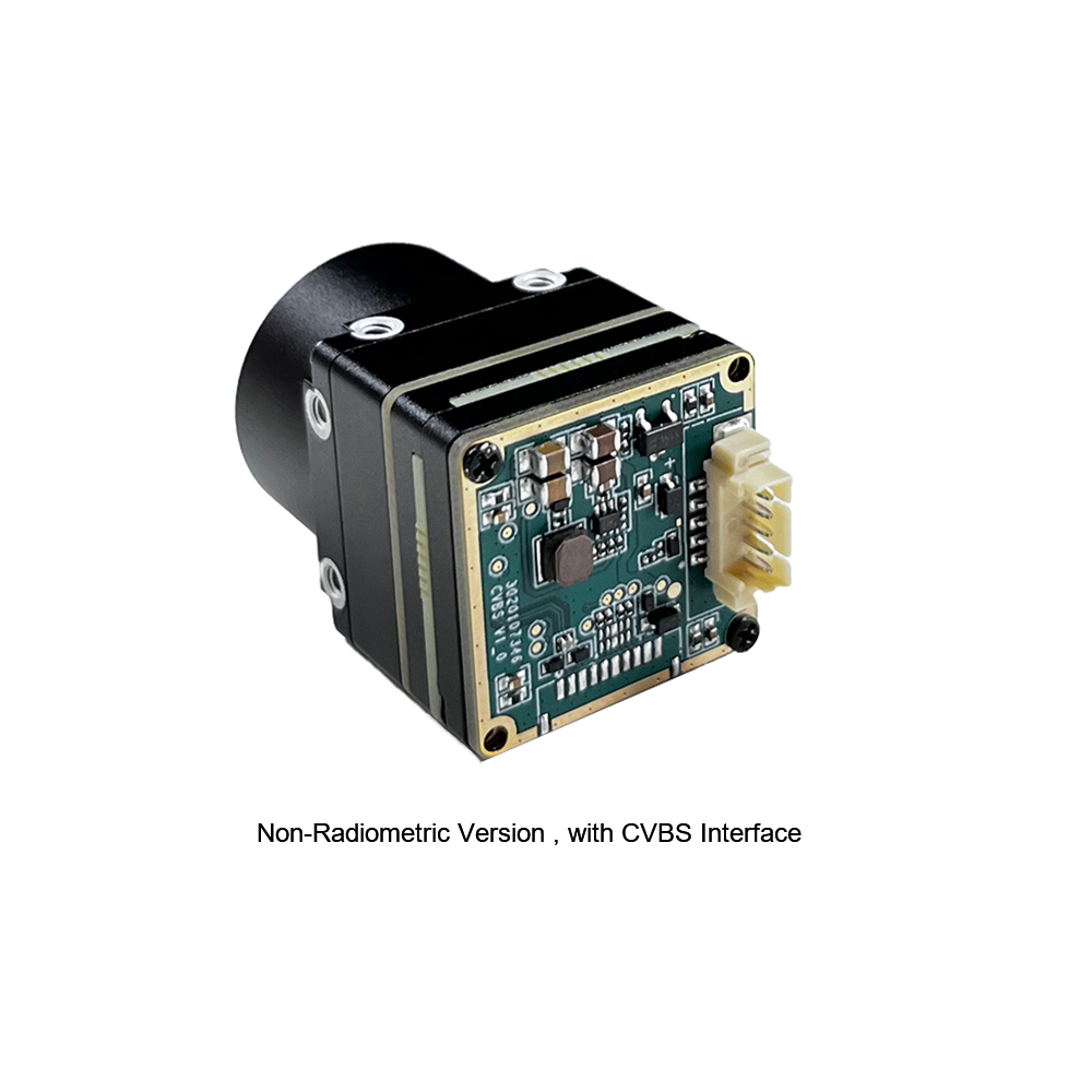
وحدة كاميرا حرارية مصغرة غير مبردة 384*288 للطائرات بدون طيار
The MINI series infrared thermal imaging module is a compact, high-precision thermal imager designed for direct integration. Featuring a sensitive detector core, stable performance, and essential system interfaces, it fits right into machine vision, drone payloads, automated safety inspections, and equipment monitoring platforms.
Technical Specification Breakdown
| Core Detector Array | 384 × 288 High-Sensitivity Uncooled Microbolometer |
| Video Interface Format | Analog CVBS Output with low-latency signal routing |
| Form Factor & SWaP | Ultra-miniaturized body designed for lightweight airborne gimbals |
| النشر الأساسي | Machine vision, safety inspection, smart manufacturing, drone payloads |

وحدة كاميرا استشعار حراري غير مبردة RJ45 CVBS RTSP IP بدقة 640*512
Powered by a high-efficiency ASIC processing core, this 640*512 thermal imaging camera module delivers detailed resolution alongside dual RJ45 Ethernet IP and CVBS analog outputs. Built specifically for long-range UAV search-and-rescue, site surveillance, and edge AI video pipelines.
Technical Specification Breakdown
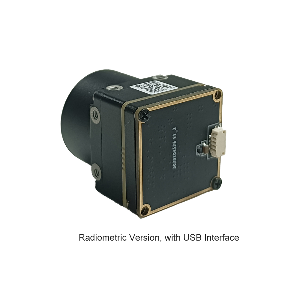
| Core Detector Array | 640 × 512 High-Resolution Uncooled Microbolometer |
| بنية المعالجة | Dedicated Low-Power Hardware ASIC Processing Core |
| Interface Ecosystem | RJ45 Ethernet (RTSP / IP) + Concurrent CVBS Analog Output |
| النشر الأساسي | Enterprise drone systems, edge AI video platforms, long-range SAR |
Master OEM Thermal Module Comparison Matrix
| Product Model | Visual Reference | دقة المصفوفة | Connectivity Profiles | Target Application Focus | Direct Datasheet Link |
|---|---|---|---|---|---|
| وحدة كاميرا حرارية مصغرة غير مبردة 384*288 للطائرات بدون طيار |
|
384 × 288 بكسل Microbolometer |
• Analog CVBS Output • Compact Pin Headers |
• Lightweight drone gimbals • Smart manufacturing • Machine vision inspection |
Open Specs ➔ |
| Uncooled Infrared RJ45 CVBS RTSP IP 640*512 Thermal Module |
|
640 × 512 بكسل ASIC Engine Core |
• RJ45 IP (RTSP / ONVIF) • Concurrent Analog CVBS |
• High-altitude SAR drones • Automated AI vision analytics • Perimeter monitoring |
Open Specs ➔ |
المعايرة البصرية، وتصحيح عدم الانتظام (NUC)، ومقاييس قياس درجة الحرارة
Getting clean image feeds out of an uncooled وحدة التصوير takes solid calibration. Microbolometers react constantly to external temperature shifts. Without active image corrections, your video stream will degrade and thermal measurements will drift off target.
Non-Uniformity Correction (NUC) Mechanics
Because micro-fabrication isn't 100% uniform across an array, every single pixel on a microbolometer has slightly different gain and resistance characteristics. Add in internal warmth from driving electronics, and you get fixed-pattern noise (FPN) and vertical streaks across your image if it isn't corrected.
- ⚙️ Mechanical Shutter Calibration (Shutter-Based NUC): The module drops a mechanical shutter flag in front of the array for a fraction of a second, presenting a flat, uniform thermal baseline. The DSP uses this event to reset pixel gain offsets. It works well, but it causes a brief video pause (about 200ms–500ms), which can disrupt auto-tracking algorithms.
- ⚙️ Shutterless Scene-Based NUC Algorithms: Modern modules run intelligent shutterless NUC routines. These mathematical models evaluate scene motion along with internal temperature sensors on the ROIC board to update offset values continuously. You get smooth, uninterrupted video feeds—critical for fast tactical drone operations.
Radiometric Temperature Measurement Math
It's important to differentiate between visual thermal cores (built for high-contrast viewing) and full radiometric temperature measurement engines. Radiometric cores calculate true target surface temperatures across every single pixel by factoring in atmospheric losses and target surface emissivity.
The total heat radiance ($W_{\text{total}}$) picked up by a microbolometer pixel follows the Stefan-Boltzmann radiometric transport model:
حيث:
- ⚙️ τ (Tau): Atmospheric transmittance factor along the line-of-sight path.
- ⚙️ ε (Epsilon): Surface emissivity coefficient of the target material (e.g., bare shiny metal $\approx 0.05$, matte paint $\approx 0.95$).
- ⚙️ σ (Sigma): The Stefan-Boltzmann constant ($5.670374 \times 10^{-8} \text{ W/m}^2\text{K}^4$).
- ⚙️ T_target: Absolute target temperature (Kelvin).
- ⚙️ T_ambient: Reflected background temperature (Kelvin).
- ⚙️ T_atmosphere: Ambient air temperature along the path (Kelvin).
By solving this balance equation continuously inside the ASIC firmware, radiometric cores generate accurate temperature readings across changing outdoor conditions. For a broader look at adapting standard camera designs for thermal operation, read our overview on Converting Standard Optical Engines to Thermal Imaging Systems.
دليل الأسئلة الشائعة التقنية الصناعية
How can I stream video from an IP-enabled thermal imaged module into a custom OpenCV processing pipeline?
Connecting an IP-enabled module—like the Uncooled Infrared RJ45 CVBS RTSP IP 640*512 Module—into a custom computer vision pipeline is straight forward over local network lines. The onboard hardware encoder outputs standard H.264 or H.265 streams accessible via RTSP URIs.
Here is a battle-tested Python setup using OpenCV to pull frames directly into memory:
import cv2

# Module RTSP network endpoint
rtsp_stream_uri = "rtsp://192.168.1.100/live/main"

# Initialize capture stream via FFMPEG backend
cap = cv2.VideoCapture(rtsp_stream_uri, cv2.CAP_FFMPEG)

if not cap.isOpened():
    print("Error: Unable to connect to thermal module stream.")
    exit()

while True:
    ret, frame = cap.read()
    if not ret:
        print("Error: Frame capture failed.")
        break

    # Process thermal frame (e.g., edge detection, target identification)
    gray_thermal = cv2.cvtColor(frame, cv2.COLOR_BGR2GRAY)

    # Render processed thermal frame
    cv2.imshow("OEM Thermal Module RTSP Stream", gray_thermal)

    if cv2.waitKey(1) & 0xFF == ord('q'):
        break

cap.release()
cv2.destroyAllWindows()
If you're running edge analytics, push this script to an embedded platform like an NVIDIA Jetson module mounted right next to the camera core to run real-time target detection models directly on incoming RTSP frames.
What critical criteria dictate thermal core selection for miniature UAV gimbal payloads?
Choosing an OEM thermal engine for lightweight drone gimbals requires balancing four core requirements:
- ⚙️ SWaP Constraints (Size, Weight, Power): Payload weight drops airframe flight times fast. Pick low-power ASIC cores (<1.5W draw) to keep battery drain down and prevent heat build-up inside tight gimbal shells.
- ⚙️ Resolution and Pixel Pitch: For close-up or low-altitude work, a 384×288 array gets the job done cleanly. For higher altitude flights or search-and-rescue work, go with a 640×512 array with 12µm pixel pitch to maintain high spatial detail at a distance.
- ⚙️ Video Latency & Control Interface: Manual piloting needs low delay—use analog CVBS (<10ms) for real-time control. For onboard AI tracking, feed high-resolution RTSP streams straight into your compute hardware.
- ⚙️ Ruggedization: Drone payloads take plenty of shock, vibration, and thermal exposure. Verify the thermal core supports extended operational ranges (-40°C to +80°C) with rigid mounting locations to keep optics aligned under heavy flight loads.
How do radiometric thermal camera modules differ operational-wise from standard thermal imaging cores?
The difference between standard thermal engines and radiometric thermal engines comes down to raw data processing and absolute temperature reporting:
Standard Thermal Camera Modules: These are built purely for image visual quality. They use Automatic Gain Control (AGC) curves to enhance image contrast, making targets pop against colder backgrounds. However, standard cores don't measure calibrated temperature values—pixel brightness simply shows relative heat contrast in the scene.
Radiometric Thermal Camera Modules: Radiometric cores maintain continuous factory and sensor-level thermal calibrations for every pixel on the detector array. By factoring in surface emissivity, distance, atmospheric loss, and ambient humidity, radiometric modules calculate real surface temperatures across the image. That makes them mandatory for utility inspections, solar panel checks, and fire monitoring applications where exact target temperatures are required.
How do optical lens parameters (Focal Length and F-Number) impact thermal range and NETD sensitivity?
The front optics act as the primary light collector, setting strict physical limits on spatial range and system noise:
Focal Length ($f$): Focal length directly dictates field of view (FOV) and optical magnification. Longer focal lengths narrow the view, focusing pixel density on distant targets to boost Detection, Recognition, and Identification (DRI) ranges. But keep in mind: long Germanium lenses add mass and footprint quickly, which can challenge strict SWaP limits.
Lens Aperture ($F$-Number): The $F$-number marks the light-gathering speed of the lens setup. Lower $F$-numbers (e.g., $F/1.0$ vs $F/1.4$) let significantly more infrared energy reach the microbolometer array. Opening up the aperture improves overall system thermal sensitivity (lower effective NETD), providing cleaner frames in low-contrast conditions. For enterprise setups, an $F/1.0$ to $F/1.2$ lens offers the ideal performance balance.
عند إحكام إغلاق نواة حرارية غير مبردة داخل علبة مقاومة للطقس IP67/IP68، يكون التصميم الحراري السلبي حاسمًا لإيقاف الانحراف الحراري الأساسي وتدهور الصورة. لا تحتاج الميكروبولومترات إلى مبردات نشطة، لكن ASIC الصورة المدمجة ومشفرات الفيديو الشبكية تستهلك بين 1.0 واط و 2.5 واط أثناء التشغيل. في صندوق محكم ضيق بدون تدفق هواء، تخلق الحرارة الداخلية المحتبسة نقاطًا ساخنة عبر هيكل النواة ومصفوفة المستوى البؤري. تؤدي هذه التدرجات الحرارية الموضعية إلى خلل في قراءات درجة الحرارة الإشعاعية وتزيد من ضوضاء المستشعر، مما يقلل من حساسية NETD الفعالة لديك. لحل هذا، صمم مسارات مباشرة لتبديد الحرارة المعدنية—مثل كتلة باردة من الألومنيوم أو النحاس مقترنة بوسادات فجوة عالية التوصيل—تربط اللوحة الحرارية للوحدة مباشرة بالغلاف المعدني الخارجي. هذا يحول كامل الهيكل الخارجي إلى مشتت حراري كبير. أيضًا، تجنب تركيب أجزاء عالية الطاقة (مثل أجهزة الراديو RF أو محولات الطاقة الساخنة) بجوار النواة البصرية مباشرة للحفاظ على استقرار الظروف الحرارية عبر المستشعر.
- المعيار الصناعي: OBSETECH Advanced Drone Platform Integrations
- دليل ذو صلة: LTC Multi-Functional Thermal Module Architecture Analysis
- AI Integration Manual: Top Thermal Camera Modules for UAV AI Processing Systems
- مرجع تقني: Adapting Standard Electro-Optical Engines to Infrared Cores