Najlepszy moduł kamery termowizyjnej 256x192 25mm do samodzielnie budowanych lunet i dronów: Ekonomiczny czujnik IR dalekiego zasięgu
3 lipca 2026
Moduł kamery termowizyjnej 640x512 VOx: Kompletny przewodnik po Edge AI, dronach i transmisji na żywo
6 lipca 2026
Moduł Kamery Termowizyjnej 90mm z Edge AI: Precyzja Dalekiego Zasięgu
W monitoringu optycznym dalekiego zasięgu, nadzorze przemysłowym i ładunkach użytkowych dronów klasy obronnej zapotrzebowanie na akwizycję celów o wysokiej rozdzielczości na dużych odległościach jest krytyczne. Standardowe obiektywy szerokokątne nie zapewniają rozdzielczości przestrzennej w zasięgu celu ($IFOV$) wymaganej do pozytywnej identyfikacji poza kilkaset metrów. Integracja modułu kamery termowizyjnej 90 mm wypełnia tę lukę operacyjną. Łącząc wysokoprecyzyjny, niechłodzony mikrobolometr o rastrze pikseli 17 µm lub 12 µm z zespołem germanowego obiektywu o długiej ogniskowej 90 mm, architekci systemów mogą osiągnąć wąskie pola widzenia (FOV) zoptymalizowane do obserwacji na odległości kilometrów. Po wzbogaceniu o sprzętowo przyspieszaną sztuczną inteligencję brzegową (Edge AI), moduły te przekształcają surowe dane długofalowej podczerwieni (LWIR) w użyteczne informacje bezpośrednio na brzegu sieci, redukując opóźnienia i eliminując ogromne obciążenie pasma związane z przesyłaniem strumieni surowych tabel wideo termicznego przez łącza bezprzewodowe.
Zespoły inżynieryjne integrujące technologie podczerwieni w niestandardowych celownikach taktycznych, platformach dronów wysokogórskich czy systemach ochrony perymetrycznej potrzebują więcej niż gotowych, konsumenckich komponentów. Ten plan analizuje wymagania strukturalne, optyczne i radiometryczne rdzeni kamer termowizyjnych LWIR 90 mm. Badamy, jak czułość na poziomie piksela — mierzona za pomocą różnicy temperatur ekwiwalentnej szumom (NETD) — współdziała z profilami transmisji optycznej, aby określić rzeczywistą maksymalną wydajność zasięgu w warunkach rzeczywistej atenuacji atmosferycznej. Poprzez szczegółowe analizy architektoniczne, przewodniki integracji sprzętowej i porównawcze badania produktów, ten podręcznik techniczny służy jako ostateczne odniesienie do wdrażania profesjonalnych, inteligentnych ładunków użytkowych LWIR.
Oto sedno: jeśli budujesz systemy przeznaczone do działania w zmiennych, rzeczywistych środowiskach, nie możesz polegać na teoretycznych, najlepszych scenariuszach. Musisz projektować z myślą o najgorszym przypadku dyspersji atmosferycznej i maksymalizować swoje przewagi optyczne od samego początku. W warsztacie nazywamy to inżynierią dla rzeczywistości termicznej, a nie dla karty katalogowej.

Spis treści
- 👉 Fizyka optyczna i współczynniki rozdzielczości przestrzennej
- 👉 Architektury integracji sprzętu elektronicznego
- 👉 Odblokowanie Edge AI: Wnioskowanie w czasie rzeczywistym na sensorze
- 👉 Przegląd porównawczy przemysłowych modułów rdzeniowych LWIR
- 👉 Ramy integracji: UAV, celowniki taktyczne i robotyka autonomiczna
- 👉 Pogłębione najczęściej zadawane pytania
Fizyka optyczna i współczynniki rozdzielczości przestrzennej
1 Obliczenia ogniskowej obiektywu a IFOV
Podstawową funkcją obiektywu o ogniskowej 90 mm sparowanego z długofalową podczerwienią (LWIR) Wikipedia Mikrobolometr jest ograniczenie chwilowego pola widzenia ($IFOV$), a tym samym maksymalizacja rozdzielczości przestrzennej na długich ścieżkach celu. $IFOV$, reprezentujący projekcję kątową pojedynczego elementu detektora (piksela) w przestrzeń obiektową, jest podstawową metryką. Jest on matematycznie sformułowany jako:
$$IFOV = \frac{p}{f}$$
gdzie $p$ to fizyczny raster pikseli matrycy sensora (zazwyczaj 12 µm lub 17 µm dla standardowych rdzeni przemysłowych), a $f$ to efektywna ogniskowa zespołu optycznego (90 mm).
Dla rdzenia sensora 12 µm zintegrowanego z obiektywem 90 mm:
$$IFOV_{12\mu m} = \frac{12 \times 10^{-6}\text{ m}}{90 \times 10^{-3}\text{ m}} \approx 0,133\text{ mrad}$$
Z kolei dla starszego sensora 17 µm:
$$IFOV_{17\mu m} = \frac{17 \times 10^{-6}\text{ m}}{90 \times 10^{-3}\text{ m}} \approx 0,189\text{ mrad}$$
Zwróć uwagę, że zmniejszenie rastra pikseli z 17 µm do 12 µm daje 29,6% redukcji kątowego rozmiaru piksela. Przekłada się to bezpośrednio na gęstsze próbkowanie celów na odległość. W praktyce terenowej rozdzielczość przestrzenną na dystansie 1000 metrów ($S_{1000}$) oblicza się według wzoru:
$$S_{1000} = 1000\text{ m} \times IFOV$$
Oto jak to wygląda pod względem fizycznego śladu:
- ✅ Sensor 12 µm przy obiektywie 90mm: $S_{1000} \approx 0.133\text{ m} = 13.3\text{ cm}$ fizyczny ślad na piksel. Zapewnia to niezwykle ścisłą dyskretyzację przestrzenną.
- ✅ Sensor 17 µm przy obiektywie 90mm: $S_{1000} \approx 0.189\text{ m} = 18.9\text{ cm}$ fizyczny ślad na piksel. Wciąż użyteczny, ale brakuje mu precyzyjnego odwzorowania krawędzi systemu 12 µm.
Podczas planowania konfiguracji do wykrywania, śledzenia i identyfikacji dalekiego zasięgu, gęstość przestrzenna na celu podlega Kryteriom Johnsona. Dla standardowego wykrycia celu (1,5 piksela na wymiar krytyczny), cel ludzki (modelowany jako szerokość krytyczna 0,75 m) musi obejmować co najmniej 1,5 piksela.
W przypadku systemu z rdzeniem 12 µm, 90mm, maksymalny zasięg wykrywania ($R_{det}$) celu ludzkiego w idealnych warunkach transmisji atmosferycznej jest wyprowadzany dynamicznie poprzez:
$$R_{det} = \frac{\text{Wymiar Krytyczny Celu}}{IFOV \times \text{Wymagane Piksele}} = \frac{0.75\text{ m}}{0.133 \times 10^{-3}\text{ rad} \times 1.5} \approx 3,759\text{ metrów}$$
Ta wysoka gęstość przestrzenna czyni matrycę o ogniskowej 90mm kluczowym narzędziem w systemach ochrony granic perymetrycznych oraz poszukiwawczo-ratowniczych. Więcej szczegółów na temat doboru sensorów można znaleźć w naszym kompleksowym przewodniku po modułach sensorów kamer termowizyjnych.
2 Wydajność MTF w spektrum 8-14μm
Funkcja Przenoszenia Modulacji (MTF) określa zdolność systemu do przenoszenia kontrastu ze sceny optycznej na powierzchnię detektora przy zmiennych częstotliwościach przestrzennych, mierzonych w parach linii na milimetr ($\text{lp}/{\text{mm}}$). Ponieważ promieniowanie LWIR działa w pasmach spektralnych $8\ \mu\text{m} \le \lambda \le 14\ \mu\text{m}$, ograniczona dyfrakcyjnie przestrzenna częstotliwość odcięcia jest znacząco niższa niż w optyce światła widzialnego, zgodnie z zależnością:
$$\xi_{odcięcia} = \frac{1}{\lambda \cdot F\#}$$
Pracując przy $F/1.25$ ze średnią długością fali $\lambda = 10\ \mu\text{m}$, absolutna termodynamiczna granica optycznej funkcji przenoszenia wynosi:
$$\xi_{odcięcia} = \frac{1}{10 \times 10^{-3}\text{ mm} \times 1.25} = 80\text{ lp/mm}$$
Standardowe zespoły soczewek germanowych 90mm, skonfigurowane do systemów dwupolowych (dual-FOV) lub z ciągłym zoomem, wykorzystują powłoki antyrefleksyjne (AR) oraz twarde powłoki węglowe/diamentopodobne (DLC), aby przetrwać degradację środowiskową i zminimalizować wewnętrzne odbicia Fresnela.
Aby utrzymać wydajność MTF na poziomie systemu powyżej $35\%$ kontrastu przy częstotliwości Nyquista mikroblometru 12 µm ($\approx 41.6\text{ lp/mm}$), zespół optyczny musi korygować aberracje sferyczne, chromatyczne i astygmatyczne natywnie w swoim wieloelementowym stosie germanowym. Źle zaprojektowane soczewki degradują optyczną MTF poniżej limitu Nyquista sensora, wprowadzając aliasing przestrzenny i obniżając efektywną czułość termiczną zintegrowanego systemu kamery.
Architektury integracji sprzętu elektronicznego
1 Natywne trasowanie mostka równoległego CMOS do MIPI CSI-2/USB 3.0
Na poziomie fizycznej warstwy krzemowej, surowy sygnał cyfrowy z niechłodzonego mikrobolometru składa się z szybkiej, niskonapięciowej równoległej magistrali CMOS (często 14-bitowe surowe dane cyfrowe sparowane z sygnałami sterującymi: zegarem pikseli `PCLK`, sygnałem ważności linii `LVAL` i sygnałem ważności ramki `FVAL`). Wysokowydajne rdzenie termowizyjne konwertują tę równoległą magistralę lokalnie na nowoczesne topologie szeregowych łączy o dużej gęstości, takie jak MIPI CSI-2 lub interfejsy USB 3.0/Type-C, aby obsługiwać wysoki zakres dynamiczny i szybki transfer danych.
Podczas prowadzenia tych sygnałów różnicowych na wielowarstwowej płycie głównej, inżynierowie muszą precyzyjnie skonfigurować impedancje docelowe zgodnie z tymi ścisłymi układami fizycznymi:
- ⚙️ Pary różnicowe MIPI CSI-2: Muszą utrzymywać stałą impedancję różnicową $100\ \Omega$ ($\pm 10\%$), aby zapobiec problemom z odbiciami transmisji wysokiej częstotliwości na liniach zegara i danych.
- ⚙️ USB 3.0 SuperSpeed (TX/RX): Wymaga prowadzenia z impedancją różnicową $90\ \Omega$.
- ⚙️ Odniesienia do płaszczyzn masy: Poprowadź nieprzerwane płaszczyzny masy bezpośrednio pod wszystkimi ścieżkami szybkich sygnałów, aby odizolować szum cyfrowy od wrażliwego analogowego front-endu bolometru.
Dodatkowo, skośność wewnątrz pary musi być ograniczona do $<0.15\text{ mm}$ poprzez symetryczne trasowanie ścieżek i dopasowywanie długości wężownicą, aby zapobiec przesunięciom fazowym sygnału przy szybkich przejściach. Deweloperzy mogą dowiedzieć się więcej o wysokiej integralności warstw płyt w naszym Przewodnik integracji modułu mikro kamery termowizyjnej LWIR.
Do integracji z automatycznymi platformami pozycjonującymi i wieloczujnikowymi gimbalami stabilizacyjnymi, Shenzhen ChiYi Electronics Co., Ltd. zapewnia wyspecjalizowane, niskolatencyjne konwertery interfejsów. Te komponenty łączą przemysłowe magistrale równoległe LWIR z cyfrowymi wyjściami wideo, takimi jak HD-SDI, LVDS lub HDMI, zachowując integralność sygnału na długich trasach wiązek.
2 Interfejsy na poziomie SDK dla wbudowanych SBC
Aby pobrać surowe 14-bitowe zestawy danych radiometrycznych do komputera jednopłytkowego (SBC), takiego jak Raspberry Pi 4/5, NVIDIA Jetson Orin Nano lub niestandardowe bloki przetwarzania ARM/FPGA, deweloperzy muszą wykorzystać SDK rdzenia termicznego. Potok integracji działa przez standardowe magistrale interfejsów, wyodrębniając ładunek bezpośrednio do surowych buforów pamięci. Proces rozpoczyna się od utworzenia instancji nasłuchiwaczy surowego strumienia UVC przy użyciu backendu, takiego jak `libuvc` lub standardowych interfejsów jądra:
#includeTen surowy potok omija standardowe kodery wideo, zachowując obliczenia temperatury docelowej z dokładnością do $\pm 2^\circ\text{C}$ lub $2\%$ na lokalizację piksela.
Odblokowanie Edge AI: Wnioskowanie w czasie rzeczywistym na sensorze
1 Warstwy akceleracji sprzętowej FPGA i NPU
Przetwarzanie rdzeniowe na sensorze opiera się na koprocesorze FPGA/ASIC wykonującym zrównoleglone potoki do korekcji przestrzennej w czasie rzeczywistym, korekcji niejednorodności (NUC) i zastępowania uszkodzonych pikseli (BPR). Zastosowanie tych tablic korekcyjnych przed wnioskowaniem głębokiej sieci neuronowej zapobiega powstawaniu fałszywych alarmów w wykrywaniu celów spowodowanych przez martwe piksele i dryft kolumn.
W przypadku modeli uruchamiających cele Yolov8 lub MobileNet-SSD na lokalnych Edge NPU, 14-bitowy analityczny strumień radiometryczny jest przetwarzany równolegle. Jedna gałąź skaluje zakres dynamiczny termiczny za pomocą algorytmu adaptacyjnej projekcji histogramu do przestrzeni tensorowej INT8 odpowiedniej dla warstw sieci neuronowej. Faza kwantyzacji mapuje wariancję mikrokelwinów na solidne cechy fizyczne, umożliwiając systemom autonomicznym identyfikację personelu, struktur i maszyn w warunkach słabej widoczności lub silnego zatłoczenia.
Aby poznać natywne akceleratory AI wewnątrz kompaktowych konfiguracji LWIR, zobacz nasz Przewodnik integracji modułu LWIR wzbogaconego o Edge AI.
2 Pomiar temperatury i struktury danych radiometrycznych
Prawdziwe systemy monitoringu radiometrycznego generują surowe dane pikseli, które bezpośrednio odpowiadają rzeczywistym wartościom temperatury fizycznej. Każda wartość piksela reprezentuje wysoce skalibrowany odczyt czujnika energii promieniowania emitowanej przez obiekt docelowy. Aby utrzymać dokładność odczytu w zmiennych warunkach otoczenia, wewnętrzny algorytm kalibracji oblicza współczynniki kompensacji na podstawie kluczowych właściwości fizycznych. W praktyce nasz przepływ pracy wykorzystuje następujące parametry:
- ⚙️ Emisyjność celu ($E$): Określa wydajność emisji powierzchni materiału docelowego (kalibrowana od 0,01 do 1,00).
- ⚙️ Odległość atmosferyczna ($D$): Kompensuje straty tłumienia na ścieżce optycznej o długości 90 mm.
- ⚙️ Temperatura otoczenia ($T_{amb}$): Kompensuje odbite promieniowanie otoczenia wchodzące na ścieżkę optyczną.
Te zmienne są dynamicznie dostosowywane w oprogramowaniu za pośrednictwem rejestru sterowania SDK. Zapisanie zaktualizowanych wartości do rejestrów dostosowuje wewnętrzne obliczenia radiometryczne na podstawie odległości do celu i lokalnych warunków atmosferycznych.
Przegląd porównawczy przemysłowych modułów rdzeniowych LWIR
Aby pomóc zespołom ds. zakupów i inżynierii, poniższe szczegółowe porównanie zawiera parametry techniczne obecnie dostępnych niechłodzonych systemów rdzeniowych LWIR, skategoryzowane według gęstości pikseli, formatów wyjściowych i możliwości zasięgu.
1 Bezpośrednie parametry produktu i dopasowanie arkuszy danych
| Specyfikacje modelu | Niechłodzony mini rdzeń LWIR 256*192 | Niechłodzony mini rdzeń USB LWIR 640*512 |
|---|---|---|
| Obraz docelowy produktu | 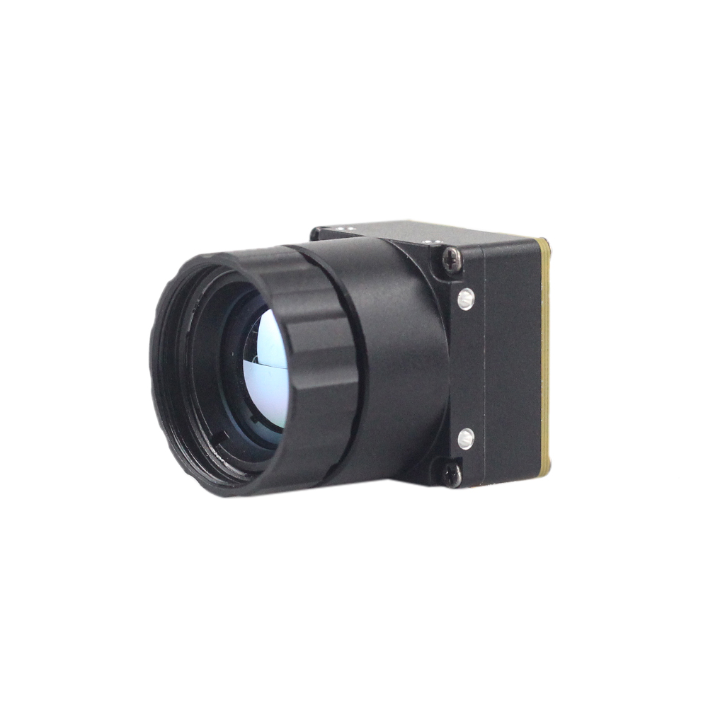 |
 |
| Rozdzielczość detektora | 256 x 192 (ultrakompaktowa obudowa) | 640 x 512 / 640 x 480 (rdzeń o wysokiej rozdzielczości) |
| Rozstaw pikseli | 12 µm | 12 µm |
| Pasmo spektralne | 8 µm do 14 µm (LWIR) | 8 µm do 14 µm (LWIR) |
| Czułość termiczna (NETD) | ≤ 50 mK (ultrawyraźny obraz termiczny) | ≤ 40 mK (ostra i wyraźna prezentacja obrazu) |
| Dostępne obiektywy (ogniskowa) | Zintegrowane stałoogniskowe obiektywy szerokokątne/średnie | Konfiguracje 5 / 9 / 13 / 18 / 35 / 50 / 75 / 100 / 150 mm |
| Waga i wymiary | Ultralekka miniaturowa konstrukcja | Podstawa o miniaturowym rozmiarze 21 mm x 21 mm, ultraniski koszt |
| Główne zastosowania | Wykrywanie min, kompaktowe UAV, lokalne mapowanie temperatury | Drony dalekiego zasięgu, śledzenie perymetryczne, celowniki termiczne |
Prezentacja: Niechłodzona mini kamera termowizyjna LWIR 256*192 podobna do DJI do wykrywania min
Mini niechłodzona kamera termowizyjna LWIR 256 wykorzystuje wysokowydajne detektory podczerwieni do ultrawyraźnego obrazowania termicznego i dokładnego pomiaru temperatury. Przechwytuje promieniowanie podczerwone i generuje jednolity obraz termiczny z radiometrią. Zapewnia to dokładność na poziomie mikro w misjach poszukiwawczo-ratowniczych, wdrażaniu mikro UAV i specjalistycznych misjach ograniczania zagrożeń strukturalnych.
Jej lekka konstrukcja sprawia, że idealnie nadaje się do prac teledetekcyjnych bliskiego i średniego zasięgu, gdzie liczy się każdy gram. Oferując czystą integrację z komputerami jednopłytkowymi, dostarcza surowe pola temperatury bezpośrednio przez nowoczesne magistrale cyfrowe.
Zobacz szczegóły produktu i ceny ➔
Prezentacja: Niechłodzony mini moduł kamery termowizyjnej USB LWIR 640*512 do dronów podobny do DJI
Zespoły projektowe wymagające czystej wydajności na długich kanałach detekcji polegają na konfiguracjach o wysokiej rozdzielczości. Mini niechłodzony moduł kamery termowizyjnej na podczerwień charakteryzuje się ostrą i wyraźną prezentacją obrazu, kompaktowymi rozmiarami i niskim kosztem. Dzięki miniaturowemu rozmiarowi 21 mm*21 mm i ogniskowym obiektywów obejmującym 5/9/13/18/35/50/75/100/150 mm oraz opcjonalnej rozdzielczości 640*480, zapewnia stabilną wydajność i silną adaptowalność środowiskową.
W połączeniu z konfiguracjami teleobiektywów i zoomu do 90 mm lub 150 mm, zapewnia wyraźne sygnatury fizyczne celów oddalonych o kilka kilometrów. Ten poziom rozdzielczości ma kluczowe znaczenie dla zautomatyzowanej obrony perymetrycznej, ochrony infrastruktury krytycznej i operacji poszukiwawczych z użyciem dronów.
Zobacz szczegóły produktu i ceny ➔
Ramy integracji: UAV, celowniki taktyczne i robotyka autonomiczna
Wdrożenie solidnych możliwości termowizyjnych w rzeczywistych ładunkach wymaga starannego wyważenia kwestii mechanicznych, termicznych i optycznych, aby chronić elektronikę na poziomie rdzenia.
1 Rozważania dotyczące SWaP ładunku drona
W przypadku ograniczeń rozmiaru, wagi i mocy (SWaP) w bezzałogowych statkach powietrznych (UAV), integracja obiektywu o ogniskowej 90 mm wprowadza przesunięcie masy, które przesuwa środek ciężkości czujnika do przodu.
- ✅ Przesunięcie masy: Teleobiektyw germanowy 90 mm może ważyć od $180\text{ g}$ do $350\text{ g}$, w porównaniu do lekkiego rdzenia ultra-mikrobolometrycznego o masie $15\text{ g}$.
- ✅ Wyważanie gimbala: Umieszczenie zespołu rdzeń-czujnik za ciężkim obiektywem przesuwa docelowy punkt równowagi do przodu. Fizyczny środek ciężkości na niestandardowych dwuosiowych gimbalach bezszczotkowych musi być ręcznie wyważany wzdłuż osi pochylenia. Zapewnia to, że silniki gimbala nie przegrzewają się ani nie pogarszają integralności pętli sterowania podczas korekcji przy silnym wietrze o wysokiej częstotliwości.
Szczytowe wymagania dotyczące momentu obrotowego silnika ($T_m$) są obliczane na podstawie przewidywanych obciążeń wiatrem i operacyjnych przyspieszeń kątowych:
$$T_m = I_{oś} \cdot \alpha_{docelowe}$$
gdzie $I_{oś}$ to łączny moment bezwładności obiektywu 90 mm i struktury rdzenia, a $\alpha_{docelowe}$ to docelowa prędkość reakcji kątowej. Zapewnienie, że system gimbala ma odpowiedni moment trzymający, zapobiega poślizgowi śledzenia w turbulentnych warunkach lotu.
Dodatkowo, system rdzenia 90 mm pobierający do $1,5\text{ W}$ przy szczytowej wydajności (zazwyczaj podczas automatycznych cykli kalibracji migawki) musi być zasilany przez ekranowane przetwornice obniżające DC-DC typu buck. Zapobiega to zakłóceniom elektromagnetycznym wysokiej częstotliwości (EMI), które mogłyby pogorszyć działanie GPS, kompasu i komunikacji telemetrycznej UAV.
2 Zakres i wytrzymała optomechanika celowników broni
Aby zastosować niechłodzone zespoły termiczne 90 mm w taktycznych systemach celowniczych, mocowania i wewnętrzna elektronika muszą wytrzymywać wysokie, nagłe siły mechaniczne:
- ⚙️ Izolacja wstrząsów i wibracji: Zespoły celownicze mogą doświadczać przyspieszeń impulsowych przekraczających $1 000\text{ G}$ w czasie krótszym niż milisekunda podczas odrzutu. Rdzenie czujników muszą być izolowane od wstrząsów wewnątrz głównej obudowy frezowanej CNC za pomocą strukturalnych tłumików fluorosilikonowych. Chroni to zarówno ceramiczną obudowę mikrobolometru z uszczelnieniem szklanym, jak i podzespół optyczny.
- ⚙️ Uszczelnienie atmosferyczne i środowiskowe: Lunety celownicze muszą utrzymywać obojętne środowisko wewnętrzne podczas gwałtownych zmian temperatury i ciśnienia. Obudowy powinny być wypełnione azotem i uszczelnione podwójnymi pierścieniami O-ring Viton do stopnia ochrony IP67. Zapobiega to kondensacji wilgoci na wewnętrznych powierzchniach optycznych elementów soczewki germanowej.
- ⚙️ Izolacja termiczna i jednorodność: Zmiany temperatury lufy mogą przenosić ciepło do obudowy lunety, tworząc wewnętrzne gradienty termiczne. Izolowanie rdzenia podczerwieni od pierścieni montażowych za pomocą pierścieni izolacji termicznej z Delrinu lub laminatu G10 pomaga utrzymać przestrzenną jednorodność temperatury na matrycy detektora. Minimalizuje to dryft kalibracji i zapewnia dokładne wykrywanie celów podczas długotrwałych operacji.
Pogłębione najczęściej zadawane pytania
Czy mogę przesyłać strumieniowo dane termiczne o wysokiej rozdzielczości w czasie rzeczywistym z modułu 90 mm do Raspberry Pi lub Arduino?
Natomiast mikrokontrolery 8-bitowe lub 32-bitowe, takie jak Arduino Uno, ESP32 czy STM32, nie mają przepustowości magistrali pamięci i mocy obliczeniowej wymaganej do strumieniowania wideo w wysokiej rozdzielczości w czasie rzeczywistym. Ramka $640\times512$ przy 16 bitach na piksel wymaga $655 360\text{ bajtów}$ fizycznej pamięci RAM na bufor ramki, co przekracza całkowitą pojemność RAM standardowych mikrokontrolerów. W przypadku lekkich integracji z mikrokontrolerami można użyć próbkowanego w dół strumienia telemetrii SPI lub szeregowego o niskiej przepływności do przechwytywania surowych odczytów temperatury przy niższych częstotliwościach klatek (zazwyczaj $\le 2\text{ fps}$). Alternatywnie, aplikacje o wysokiej wydajności powinny wykorzystywać dedykowane procesory wbudowane do strumieniowania pełnoklatkowego wideo termowizyjnego w wysokiej rozdzielczości.
Jak sprawdza się moduł termowizyjny 90 mm w niestandardowych lunetach DIY, integracji z UAV i projektach montowanych na pojazdach?
$$HFOV = 2 \cdot \arctan\left(\frac{640 \times 12 \times 10^{-6}\text{ m}}{2 \times 90 \times 10^{-3}\text{ m}}\right) \approx 4,88^\circ$$
To wąskie pole widzenia koncentruje rozdzielczość przestrzenną czujnika na silnie skupionym obszarze, umożliwiając klasyfikację celów na dalekim dystansie, której nie mogą rozróżnić standardowe rdzenie szerokokątne (np. modele 9 mm lub 13 mm). W przypadku montażu na dronach i pojazdach to wysokie powiększenie optyczne pozwala operatorom zachować bezpieczną odległość, jednocześnie rejestrując wyraźne, szczegółowe obrazy termowizyjne. Jednak węższe pole widzenia zwiększa również wrażliwość na wibracje mechaniczne. Integracja tych systemów na platformach ruchomych zazwyczaj wymaga aktywnej stabilizacji, takiej jak szybki gimbal bezszczotkowy, lub algorytmów elektronicznej stabilizacji obrazu (EIS) w niestandardowych lunetach taktycznych, aby utrzymać stabilny obraz i zapobiec utracie śledzenia celu.
Dlaczego warto wybrać profesjonalny rdzeń termowizyjny Edge AI zamiast używanego czujnika samochodowego lub taniego czujnika DIY?
Dzięki profesjonalnemu termicznemu rdzeniowi Edge AI, deweloperzy zyskują dostęp do kompleksowych zestawów SDK, otwartych standardów oprogramowania układowego, konfiguracji API oraz skalibrowanych danych radiometrycznych ($Kelwin = LSB / 100$) bezpośrednio przez standardowe połączenia cyfrowe. Nowoczesne rdzenie posiadają również wbudowane akceleratory sprzętowe dla potoków inteligencji, umożliwiając deweloperom wykonywanie śledzenia, detekcji obiektów i wyzwalania alarmów anomalii temperaturowych bezpośrednio na rdzeniu, bez potrzeby stosowania ciężkich zewnętrznych modułów przetwarzających.
📚 Referencje i dalsza lektura
- Standard branżowy: Wikipedia Mikrobolometr
- Portal producenta: Shenzhen ChiYi Electronics Co., Ltd.
- Przewodniki integracyjne: