








Best 256x192 25mm Thermal Camera Module for DIY Scopes & Drones: Cost-Effective Long-Range IR Sensor
2026年7月3日
640x512 VOx Thermal Camera Module: The Ultimate Guide for Edge AI, Drones & Live Streaming
2026年7月6日
90mm Thermal Imaging Camera Module with Edge AI: Long-Range Precision
In long-range optical monitoring, industrial surveillance, and defense-grade UAV payloads, the demand for high-resolution target acquisition at extended distances is critical. Standard wide-angle lenses fail to deliver the spatial resolution at target range ($IFOV$) required for positive identification beyond a few hundred meters. The integration of a 90mm thermal imaging camera module bridges this operational gap. By pairing a high-precision, 17µm or 12µm pixel-pitch uncooled microbolometer with a 90mm long-focal-length germanium lens assembly, system architects can achieve narrow fields of view (FOV) optimized for kilometers-range observation. When enhanced with hardware-accelerated Edge AI, these modules transform raw Long-Wave Infrared (LWIR) data into actionable intelligence directly at the edge, reducing latency and eliminating the massive bandwidth overhead of streaming raw thermal video tables over wireless downlinks.
Engineering teams integrating infrared technologies into custom tactical scopes, high-altitude drone platforms, or perimeter security systems require more than off-the-shelf, consumer-grade components. This blueprint analyzes the structural, optical, and radiometric requirements of 90mm LWIR thermal camera cores. We inspect how pixel-level sensitivity—measured via Noise Equivalent Temperature Difference (NETD)—interacts with optical transmission profiles to determine true maximum range performance under real-world atmospheric attenuation. Through detailed architectural examinations, hardware integration guides, and comparative product examinations, this technical manual serves as the definitive reference for deploying professional-grade, intelligent LWIR payloads.
Here's the deal: if you are building systems meant to operate in volatile, real-world environments, you cannot rely on theoretical best-case numbers. You need to design for worst-case atmospheric dispersion and maximize your optical advantages from day one. In the shop, we refer to this as engineering for the thermal reality, not the datasheet.

Table of Contents
- 👉 1. Optical Physics & Spatial Resolution Coefficients
- 👉 2. Electronic Hardware Integration Architectures
- 👉 3. Unlocking Edge AI: On-Sensor Real-Time Inference
- 👉 4. Comparative Review of Industrial LWIR Core Modules
- 👉 5. Integration Frameworks: UAV, Tactical Scopes, and Autonomous Robotics
- 👉 6. Deep-Dive Frequently Asked Questions
1. Optical Physics & Spatial Resolution Coefficients
1.1 Lens focal length vs. IFOV calculations
The primary function of a 90mm focal length lens paired with a long-wave infrared (LWIR) Wikipedia Microbolometer is to constrain the instantaneous field of view ($IFOV$), thereby maximizing spatial resolution over long target paths. The $IFOV$, representing the angular projection of a single detector element (pixel) into object space, is a fundamental metric. It is mathematically formulated as:
$$IFOV = \frac{p}{f}$$
where $p$ is the physical pixel pitch of the sensor array (typically 12 µm or 17 µm for standard industrial cores) and $f$ is the effective focal length of the optical assembly (90 mm).
For a 12 µm sensor core integrated with a 90mm lens:
$$IFOV_{12\mu m} = \frac{12 \times 10^{-6}\text{ m}}{90 \times 10^{-3}\text{ m}} \approx 0.133\text{ mrad}$$
Conversely, for a legacy 17 µm sensor:
$$IFOV_{17\mu m} = \frac{17 \times 10^{-6}\text{ m}}{90 \times 10^{-3}\text{ m}} \approx 0.189\text{ mrad}$$
Look, decreasing the pixel pitch from 17 µm to 12 µm yields a 29.6% reduction in angular pixel size. That translates directly to a denser sampling rate of targets at range. To put this in practical field terms, spatial resolution at a distance of 1,000 meters ($S_{1000}$) is calculated via:
$$S_{1000} = 1000\text{ m} \times IFOV$$
Here is what that looks like in terms of physical footprint:
- ✅ 12 µm Sensor @ 90mm Lens: $S_{1000} \approx 0.133\text{ m} = 13.3\text{ cm}$ physical footprint per pixel. This gives you incredibly tight spatial discretization.
- ✅ 17 µm Sensor @ 90mm Lens: $S_{1000} \approx 0.189\text{ m} = 18.9\text{ cm}$ physical footprint per pixel. Still usable, but lacks the fine edge definition of the 12 µm system.
When planning long-range detection, tracking, and identification configurations, spatial density over a target is governed by the Johnson Criteria. For standard target detection (1.5 pixels across the critical dimension), a human target (modeled as 0.75m critical width) must span at least 1.5 pixels.
With a 12 µm, 90mm core system, the maximum detection range ($R_{det}$) for a human target under ideal atmospheric transmission conditions is derived dynamically through:
$$R_{det} = \frac{\text{Critical Target Dimension}}{IFOV \times \text{Required Pixels}} = \frac{0.75\text{ m}}{0.133 \times 10^{-3}\text{ rad} \times 1.5} \approx 3,759\text{ meters}$$
This high spatial density makes the 90mm focal length array a critical tool for perimeter boundary enforcement and search-and-rescue systems. More details on sensor selection can be found in our comprehensive thermal camera sensor module guide.
1.2 MTF performance in the 8-14μm spectrum
The Modulation Transfer Function (MTF) dictates the system's ability to transfer contrast from the optical scene to the detector surface at varying spatial frequencies, measured in line pairs per millimeter ($\text{lp}/{\text{mm}}$). Because LWIR radiation operates within the $8\ \mu\text{m} \le \lambda \le 14\ \mu\text{m}$ spectral bands, the diffraction-limited spatial cutoff frequency is significantly lower than that of visible light optics, governed by:
$$\xi_{cutoff} = \frac{1}{\lambda \cdot F\#}$$
Operating at $F/1.25$ with a median wavelength $\lambda = 10\ \mu\text{m}$, the absolute thermodynamic limit of the optical transfer function is:
$$\xi_{cutoff} = \frac{1}{10 \times 10^{-3}\text{ mm} \times 1.25} = 80\text{ lp/mm}$$
Standard 90mm germanium lens assemblies configured for dual-FOV or continuous-zoom systems utilize anti-reflective (AR) and hard carbon/diamond-like coatings (DLC) to survive environmental degradation and minimize internal Fresnel reflections.
To maintain system-level MTF performance above $35\%$ contrast at the Nyquist frequency of a 12 µm microbolometer ($\approx 41.6\text{ lp/mm}$), the optical assembly must correct for spherical, chromatic, and astigmatic aberrations natively within its multielement germanium stack. Poorly engineered lenses degrade the optical MTF below the sensor’s Nyquist limit, introducing spatial aliasing and lowering the effective thermal sensitivity of the integrated camera system.
2. Electronic Hardware Integration Architectures
2.1 Native Parallel CMOS to MIPI CSI-2/USB 3.0 bridge routing
At the physical silicon layer, the raw digital feed from the uncooled microbolometer consists of a high-bitrate, low-voltage parallel CMOS bus (often 14-bit raw digital data paired with pixel clock `PCLK`, line valid `LVAL`, and frame valid `FVAL` control strobes). High-performance thermal cores convert this parallel bus locally to modern high-density serial link topologies like MIPI CSI-2 or USB 3.0/Type-C interfaces to support high dynamic range and high-speed data transfer.
When routing these differential signals on a multi-layer host board, engineers must configure target impedances precisely with these strict physical layouts:
- ⚙️ MIPI CSI-2 Differential Pairs: Must maintain a constant $100\ \Omega$ differential impedance ($\pm 10\%$) to prevent high-frequency transmission reflection issues on the clock and data lanes.
- ⚙️ USB 3.0 SuperSpeed (TX/RX): Requires $90\ \Omega$ differential impedance routing.
- ⚙️ Ground Plane References: Run unbroken ground planes directly beneath all high-speed routes to isolate digital noise from the sensitive analog frontend of the bolometer.
Additionally, intra-pair skew must be limited to $<0.15\text{ mm}$ via symmetric trace routing and length snake-matching to prevent signal phase shifts on high-speed transitions. Developers can learn more about high-integrity board layups in our LWIR micro thermal camera module integration guide.
For integration with automated positioning platforms and multi-sensor stabilization gimbals, Shenzhen ChiYi Electronics Co., Ltd. provides specialized, low-latency interface converters. These components bridge industrial LWIR parallel buses to digital video outputs like HD-SDI, LVDS, or HDMI, preserving signal integrity across extended harness routings.
2.2 SDK-level interfaces for Embedded SBCs
To ingest raw 14-bit radiometric datasets into a single-board computer (SBC) like a Raspberry Pi 4/5, NVIDIA Jetson Orin Nano, or custom ARM/FPGA processing blocks, developers need to leverage the thermal core SDK. The integration pipeline executes over standard interface buses, extracting the payload directly to raw memory buffers. The process begins by instantiating raw UVC stream listeners using a backend like `libuvc` or standard kernel interfaces:
#include <iostream>
#include <libuvc/libuvc.h>

// Callback signature for processing incoming raw LWIR frames
void frame_callback(uvc_frame_t *frame, void *ptr) {
    if (frame->data_format != UVC_FRAME_FORMAT_Y16) {
        std::cerr << "Error: Incoming frame format is not 16-bit Raw Radiometric." << std::endl;
        return;
    }

    // Cast the payload data pointer to unsigned 16-bit array
    uint16_t *raw_data = static_cast<uint16_t*>(frame->data);
    int width = frame->width;
    int height = frame->height;

    // Read central frame pixel for core temperature monitoring
    int center_pixel_index = (height / 2) * width + (width / 2);
    uint16_t raw_val = raw_data[center_pixel_index];

    // Convert Kelvin hundredths representation to Celsius:
    // Temp (K) = Raw_Val / 100.0f -> Celsius = Temp (K) - 273.15f
    float temperature_celsius = (static_cast<float>(raw_val) / 100.0f) - 273.15f;

    std::printf("Center Pixel Raw: %u | Temperature: %.2f °C\n", raw_val, temperature_celsius);
}
This raw pipeline bypasses standard video encoders, preserving target temperature calculations down to $\pm 2^\circ\text{C}$ or $2\%$ accuracy per pixel location.
3. Unlocking Edge AI: On-Sensor Real-Time Inference
3.1 FPGA and NPU hardware acceleration layers
On-sensor core processing relies on an FPGA/ASIC coprocessor running parallelized pipelines for real-time spatial correction, Non-Uniformity Correction (NUC), and Bad Pixel Replacement (BPR). Applying these correction arrays before deep neural network inference prevents dead pixels and column drift from causing false positives in target detection.
For models running Yolov8 or MobileNet-SSD targets on local Edge NPUs, the 14-bit analytical radiometric stream is parallel-processed. One branch scales the thermal dynamic range using an adaptive histogram projection algorithm down to an INT8 tensor space suitable for neural network layers. The quantization phase maps microkelvin variance to robust physical features, enabling autonomous systems to identify personnel, structures, and machinery in low-visibility or highly congested environments.
To explore native AI accelerators inside compact LWIR setups, see our Edge AI enhanced LWIR module integration guide.
3.2 Temperature Measurement & Radiometric Data Structures
True radiometric monitoring systems output raw pixel data that corresponds directly to actual physical temperature values. Each pixel value represents a highly calibrated sensor capture of the radiant energy emitted by the target object. To maintain reading accuracy across varying ambient conditions, the internal calibration algorithm calculates compensation factors based on key physical properties. In practice, our workflow uses these parameters:
- ⚙️ Target Emissivity ($E$): Dictates the emission efficiency of the target material's surface (calibrated from 0.01 to 1.00).
- ⚙️ Atmospheric Distance ($D$): Compensates for path attenuation losses along the 90mm optical line-of-sight.
- ⚙️ Ambient Temperature ($T_{amb}$): Compensates for reflected ambient radiation entering the optical path.
These variables are adjusted dynamically in software via the SDK control registry. Writing updated values to the registers adapts the internal radiometric calculation based on the distance to the target and the local atmospheric conditions.
4. Comparative Review of Industrial LWIR Core Modules
To guide procurement and engineering teams, the detailed comparison below lists the technical parameters of currently available uncooled LWIR core systems, categorized by pixel density, output formats, and range capabilities.
4.1 Direct product parameters & datasheet matching
| Model Specifications | Uncooled LWIR Mini 256*192 Core | Uncooled LWIR USB Mini 640*512 Core |
|---|---|---|
| Product Target Image | 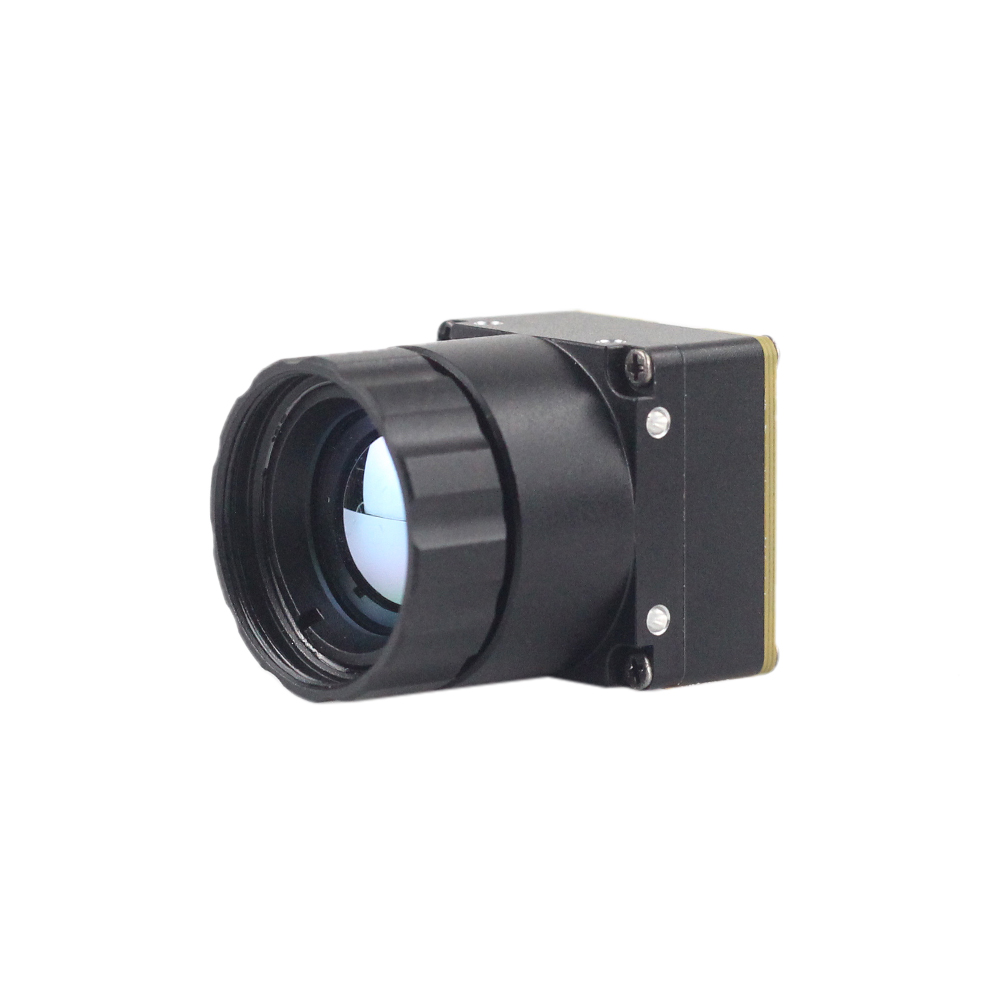 |
 |
| Detector Resolution | 256 x 192 (Ultra-Compact Form Factor) | 640 x 512 / 640 x 480 (High-Resolution Core) |
| Pixel Pitch | 12 µm | 12 µm |
| Spectral Band | 8 µm to 14 µm (LWIR) | 8 µm to 14 µm (LWIR) |
| Thermal Sensitivity (NETD) | ≤ 50 mK (Ultra-clear thermal output) | ≤ 40 mK (Sharp and crisp image presentation) |
| Available Lenses (Focal Length) | Integrated wide/mid fixed lenses | 5 / 9 / 13 / 18 / 35 / 50 / 75 / 100 / 150mm configurations |
| Weight & Dimensions | Ultra-lightweight miniature design | 21mm x 21mm base mini-size, ultra-low cost |
| Primary Applications | Detecting mines, compact UAVs, local temperature mapping | Long-range drones, perimeter tracking, thermal sights |
Showcasing: Uncooled LWIR Mini 256*192 Thermal Imaging Camera Module Similar To DJI For Detecting Mines
The Mini 256 Uncooled LWIR thermal Camera Module adopts high-performance infrared detectors for ultra-clear thermal imaging and accurate temperature measurement. It captures infrared radiation and outputs a uniform thermal image with radiometry. This brings micro-class accuracy to search-and-rescue, micro UAV deployment, and specialized structural hazard mitigation missions.
Its lightweight structure makes it ideal for close-range and medium-range remote sensing work where every gram counts. Offering clean integration on single-board computers, it delivers raw temperature fields directly over modern digital buses.
View Product Details & Pricing ➔
Showcasing: Uncooled LWIR USB Mini 640*512 Thermal Imaging Camera Core Module For Drones Similar To DJI
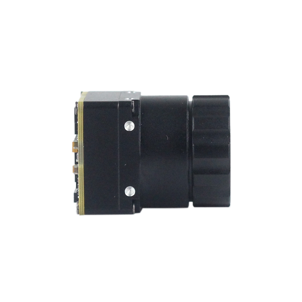
Design teams requiring clean performance over long detection channels rely on high-resolution setups. The Mini uncooled infrared thermal imaging module features in sharp and crisp image presentation, compact size and low cost. Featuring a mini-size of 21mm*21mm, and with lens focal lengths spanning 5/9/13/18/35/50/75/100/150mm and 640*480 resolution optional, it ensures stable performance and strong environmental adaptability.
When used with telephoto and zoom configurations up to 90mm or 150mm, it delivers clear physical signatures of targets several kilometers away. This level of resolution is crucial for automated perimeter defense, critical infrastructure protection, and drone-based search operations.
View Product Details & Pricing ➔
5. Integration Frameworks: UAV, Tactical Scopes, and Autonomous Robotics
Implementing robust thermal imaging capabilities within real-world payloads requires careful balancing of mechanical, thermal, and optical considerations to protect the core-level electronics.
5.1 Drone payload SWaP considerations
For Size, Weight, and Power (SWaP) constraints on unmanned aerial vehicles (UAVs), integrating a 90mm focal length lens introduces a weight offset that shifts the sensor's center of gravity forward.
- ✅ Weight Offset: A 90mm telephoto germanium lens can weigh between $180\text{ g}$ and $350\text{ g}$, compared to a lightweight $15\text{ g}$ ultra-microbolometer core.
- ✅ Gimbal Balancing: Placing the core-sensor assembly behind a heavy lens shift moves the target balance forward. The physical center of gravity on custom dual-axis brushless gimbals must be manually trim-balanced along the pitch axes. This ensures the gimbal motors don't overheat or degrade control loop integrity during high-frequency wind corrections.
Peak motor torque requirements ($T_m$) are calculated based on predicted wind loads and operational angular accelerations:
$$T_m = I_{axis} \cdot \alpha_{target}$$
where $I_{axis}$ is the combined moment of inertia of the 90mm lens and core structure, and $\alpha_{target}$ is the targeted angular response speed. Ensuring the gimbal system has adequate holding torque prevents tracking slippage in turbulent flight conditions.
Additionally, a 90mm core-system drawing up to $1.5\text{W}$ at peak performance (typically during automated calibration shutter cycles) must be powered via shielded DC-DC buck step-down converters. This prevents high-frequency electromagnetic interference (EMI) from degrading the UAV's GPS, compass, and telemetry communications.
5.2 Scope & Weapon-Sight ruggedized optomechanics
To deploy 90mm uncooled thermal assemblies in tactical sighting systems, the mountings and internal electronics must withstand high, sudden mechanical forces:
- ⚙️ Shock & Vibe Isolation: Sighting assemblies can experience impulse accelerations exceeding $1,000\text{ G}$ over sub-millisecond durations during recoil. Sensor cores must be shock-isolated within the main CNC-milled chassis using structural fluoro-silicone dampers. This protects both the ceramic microbolometer package glass seal and the optical sub-assembly.
- ⚙️ Atmospheric & Environmental Sealing: Sighting scopes must maintain an inert internal environment across rapid temperature and pressure changes. Housings should be nitrogen-purged and sealed with dual Viton O-rings to an IP67 rating. This prevents moisture from condensing on the internal optical surfaces of the germanium lens elements.
- ⚙️ Thermal Isolation & Uniformity: Changes in barrel temperature can transfer heat to the scope enclosure, creating internal thermal gradients. Isolating the infrared core from the mounting rings using Delrin or G10 fiberglass thermal isolation rings helps maintain spatial temperature uniformity across the detector array. This minimizes calibration drift and ensures accurate target detection over extended operations.
6. Deep-Dive Frequently Asked Questions
Can I stream real-time, high-resolution thermal data from a 90mm module to a Raspberry Pi or Arduino?
In contrast, 8-bit or 32-bit microcontrollers like Arduino Uno, ESP32, or STM32 lack the memory bus bandwidth and processing capacity required for real-time high-resolution video streams. A $640\times512$ frame at 16 bits per pixel requires $655,360\text{ bytes}$ of physical RAM per frame buffer, which exceeds the entire RAM capacity of standard microcontrollers. For lightweight microcontroller integrations, a downsampled low-rate SPI or serial telemetry stream can be used to capture raw temperature readings at lower frame rates (typically $\le 2\text{ fps}$). Alternatively, high-performance applications should leverage dedicated embedded processors to stream full-frame, high-resolution thermal video.
How does a 90mm thermal imaging module perform for custom DIY scopes, UAV integration, and vehicle-mounted projects?
$$HFOV = 2 \cdot \arctan\left(\frac{640 \times 12 \times 10^{-6}\text{ m}}{2 \times 90 \times 10^{-3}\text{ m}}\right) \approx 4.88^\circ$$
This narrow field of view concentrates the spatial resolution of the sensor over a highly focused area, enabling long-range target classification at distances that standard wide-angle cores (e.g., 9mm or 13mm models) cannot resolve. For drone and vehicle mounts, this high optical magnification allows operators to maintain a safe standoff distance while capturing clear, detailed thermal images. However, the narrower field of view also increases sensitivity to mechanical vibrations. Integrating these systems on moving platforms typically requires active stabilization, such as a high-frequency brushless gimbal, or electronic image stabilization (EIS) algorithms on custom tactical scopes to maintain a steady image and prevent target tracking loss.
Why choose a professional Edge AI thermal core over a salvaged automotive or cheap DIY sensor?
With a professional Edge AI thermal core, developers gain access to comprehensive SDKs, open firmware standards, API configurations, and calibrated radiometric data ($Kelvin = LSB / 100$) directly over standard digital connections. Modern cores also feature on-board hardware accelerators for intelligence pipelines, allowing developers to execute tracking, object detection, and temperature-anomaly triggering directly on the core without needing heavy external processing assemblies.
📚 References & Further Reading
- Industry Standard: Wikipedia Microbolometer
- Manufacturer Portal: Shenzhen ChiYi Electronics Co., Ltd.
- Integration Guides:





