Przewodnik po module kamery termowizyjnej MIPI: Integracja AI brzegowej wysokiej rozdzielczości dla Raspberry Pi i dronów
20 lipca 2026
Moduł kamery termowizyjnej z sensorem CMOS: Przewodnik integracji i rozwiązania OEM
21 lipca 2026 r.
Najlepsze moduły kamer termowizyjnych UVC dla Linuxa, Raspberry Pi i systemów wbudowanych
Jeśli działasz na pierwszej linii frontu przy budowie sprzętu – niezależnie od tego, czy jesteś integratorem systemów, programistą dronów montującym autonomiczne ładunki, czy inżynierem automatyki przemysłowej – doskonale znasz realia. Prawdziwym wąskim gardłem we wdrażaniu detekcji w dalekiej podczerwieni (LWIR) nie jest już fizyczna rozdzielczość sensora. Głównym utrapieniem jest coś, co nazywam "podatkiem SDK". Tradycyjne moduły rdzeni termowizyjnych są znane z wymagania zamkniętych sterowników jądra, binariów zablokowanych na platformę oraz zawiłych, zastrzeżonych potoków oprogramowania. Spróbuj sprawić, by współpracowały one z niestandardową dystrybucją Linuksa, nowoczesnym środowiskiem Robot Operating System (ROS 1 lub ROS 2) czy energooszczędnym Raspberry Pi, a szybko znajdziesz się w piekle integracji. To pochłania godziny pracy inżynierów, opóźnia wprowadzenie produktu na rynek i wprowadza ogromne luki w zabezpieczeniach konfiguracji przetwarzania brzegowego.
Oto sedno: standardowe moduły kamer termowizyjnych USB Video Class (UVC) całkowicie zmieniają zasady gry. Mapując niechłodzone sensory mikrobolometryczne LWIR bezpośrednio na natywny protokół wideo USB, moduły te udostępniają strumienie obrazowania termicznego bezpośrednio wbudowanym sterownikom systemu operacyjnego. Mówimy o Video4Linux2 (V4L2) na Linuksie i standardowych interfejsach API DirectShow/MediaFoundation w Windows. To czysty plug-and-play. Możesz pobierać surowe strumienie danych radiometrycznych lub YUV od razu po wyjęciu z pudełka, redukując narzut na integrację oprogramowania niemal do zera, uwalniając krytyczne cykle CPU na pokładzie i czyniąc wdrażanie Edge AI praktycznie wykonalnym. Ten przewodnik to kompletny, sprawdzony w boju projektowy plan wyboru, konfiguracji i programowania wysokowydajnych niechłodzonych modułów kamer termowizyjnych UVC i surowych cyfrowych w ekosystemach wbudowanego Linuksa.
Spis treści
- 👉 Czym jest natywny moduł kamery termowizyjnej UVC?
- 👉 UVC USB-C vs. MIPI CSI-2 vs. sieci (strumienie IP RJ45)
- 👉 Architektura sterownika V4L2, integracja z ROS i konfiguracje Raspberry Pi
- 👉 Dekodowanie strumienia: oddzielanie wizualnej skali szarości od surowych macierzy radiometrycznych
- 👉 Dynamika mikrobolometrów optycznych: rozmiar piksela (12 µm vs. 17 µm) i odpowiedź spektralna
- 👉 Profile produktów przemysłowych i rzeczywiste parametry wydajności
- 👉 Implementacje sterowników w C++ i Pythonie dla platform wbudowanego Linuksa
- 👉 Pogłębione techniczne FAQ
Zrozumienie modułów kamer termowizyjnych UVC
Poszerzanie horyzontów wbudowanych: czym jest moduł kamery termowizyjnej UVC?
W uproszczeniu, moduł kamery termowizyjnej UVC to po prostu niechłodzony sensor podczerwieni połączony z wbudowanym zapleczem cyfrowym, które komunikuje się w języku standardowych parametrów USB-IF UVC. W przeciwieństwie do typowych konsumenckich opcji termowizyjnych, które zmuszają do uruchamiania zastrzeżonych nakładek programowych, rdzeń UVC działa dokładnie jak standardowa kamera internetowa. Bezproblemowo integruje się z systemem operacyjnym hosta, co czyni go niezawodnym, wieloplatformowym wyborem do poważnych projektów przemysłowych.
Zajrzyjmy pod maskę. Cały proces zaczyna się od optyki. Promieniowanie dalekiej podczerwieni (zazwyczaj w paśmie spektralnym od 8 µm do 14 µm) przechodzi przez specjalistyczny element z germanu – szkło tutaj nie wystarcza – i skupia się na matrycy mikrobolometrów. Te mikrobolometry są zwykle wykonane z tlenku wanadu (VOx) lub amorficznego krzemu (a-Si). Gdy uderza w nie promieniowanie podczerwone, zmieniają swoją rezystancję w zależności od temperatury. Ta zmiana jest próbkowana przez wbudowany przetwornik analogowo-cyfrowy (ADC) i konwertowana na surowe cyfrowe rejestry wartości, zwykle o głębokości 14-bitowej lub 16-bitowej.
Następnie, wbudowany układ ASIC lub DSP zajmuje się najcięższą pracą. Wykonuje krytyczne, działające w czasie rzeczywistym korekcje, takie jak Korekcja Niejednorodności (NUC), Zastępowanie Wadliwych Pikseli (BPR) i Automatyczna Regulacja Wzmocnienia (AGC). Następnie, zamiast przesyłać te przetworzone dane przez niestandardową magistralę równoległą, układ ASIC pakuje je jako standardowe, zgodne z UVC pakiety wideo USB. Niezależnie od tego, czy łączysz się przez USB-C, micro-USB, czy wytrzymałe złącze JST płytka-płytka, urządzenie przesyła strumień bezpośrednio do rejestrów pamięci procesora hosta, korzystając z natywnych sterowników systemu operacyjnego.
W warsztacie największą zaletą jest tutaj niezawodność. Jeśli wykonasz zwykłą aktualizację jądra w systemie Ubuntu lub Debian, nie zepsuje to twojego potoku czujnika. To ogromna zaleta, gdy budujesz złożone, krytyczne maszyny, takie jak bezzałogowe statki powietrzne (UAV), gdzie komputer towarzyszący działa pod kontrolą łatki systemu operacyjnego czasu rzeczywistego, takiej jak PREEMPT_RT. Ponieważ wbudowany procesor kamery obsługuje skomplikowane obliczenia korekcyjne — NUC, zastępowanie defektów i kompresję zakresu dynamicznego — procesor główny hosta nie przeciąża się, pozostawiając swoje cykle wolne na potrzeby wizji komputerowej, planowania ścieżki lub sieci neuronowych.
Starcie interfejsów sprzętowych: UVC USB-C vs. MIPI CSI-2 vs. streamery RTSP/IP RJ45
Ocena fizycznych połączeń
Wybór odpowiedniego połączenia fizycznego wyznaczy granice dla całego twojego projektu — określa on maksymalną liczbę klatek na sekundę, limity rozdzielczości, opóźnienie systemu oraz maksymalną długość kabli. Kiedy siedzisz przy stacji CAD, projektując układ przechwytywania termicznego, zazwyczaj rozważasz trzy opcje fizyczne: USB, MIPI CSI-2 lub streaming przez zwykły Ethernet RJ45.
Interfejs UVC USB
W warsztacie uwielbiamy standardowe potoki USB, ponieważ niesamowicie ułatwiają nam życie. Poprzez fizyczny interfejs USB 2.0 lub 3.0 (zazwyczaj natywne złącze Type-C lub JST płytka-płytka), moduł ujawnia się za pomocą podstawowych, przewidywalnych deskryptorów wideo USB. Żąda punktów końcowych typu bulk lub izochronicznego i wysyła czyste, surowe strumienie cyfrowe YUYV, MJPEG lub monochromatyczne. Bez kompilowania niestandardowych sterowników jądra, bez walki z dziwnymi konfiguracjami źródłowymi — to po prostu działa.
Jedynym prawdziwym haczykiem jest tutaj fizyczne trasowanie. Standardowe pary różnicowe USB o wysokiej prędkości nie mogą być prowadzone na duże odległości bez degradacji sygnału i są bardzo wrażliwe na zakłócenia elektromagnetyczne (EMI). Jeśli projektujesz układy macierzy wewnątrz ramy drona o dużej mocy z regulatorami ESC o wysokim kV lub w pobliżu masywnych przemysłowych napędów serwo, musisz starannie ekranować linie USB. Mimo to, w przypadku systemów blisko sprzężonych, takich jak wyświetlacze nagłowne, monitory ręczne i kompaktowe urządzenia brzegowe, USB-UVC jest zdecydowanie ścieżką najmniejszego oporu.
Interfejs MIPI CSI-2
Jeśli wyciskasz każdą mikrosekundę ze swojego potoku, MIPI CSI-2 jest ciężkim zawodnikiem. Przesyła surowe, nieskompresowane dane z mikrobolometru bezpośrednio do sprzętowego procesora sygnału obrazu (ISP) w twoim CPU. Mówimy o absolutnie minimalnym opóźnieniu, gdzie klatki lądują bezpośrednio w buforach pamięci przez DMA. To standardowy wybór dla profesjonalnych, stabilizowanych gimbali dronów, gdzie pętle sterowania lotem zależą od przepływu optycznego lub śledzenia wizualnego.
Ale uwaga: koszt rozwoju jest wysoki. MIPI CSI-2 nie jest plug-and-play. Brakuje mu samoopisujących się deskryptorów. Będziesz musiał opracować własne pakiety wsparcia sprzętowego (BSP) i nakładki device-tree, a także poprowadzić szybkie linie różnicowe z rygorystycznym dopasowaniem długości ścieżek i ograniczeniami docelowej impedancji na twojej płytce PCB. Jeśli prototypujesz lub budujesz systemy w małych i średnich seriach, MIPI może stać się poważnym wąskim gardłem inżynieryjnym.
Sieć RJ45 (moduły RTSP/IP)
Gdy potrzebujesz przesłać strumień wideo przez obiekt, chcesz skonfigurować sieć. Te moduły integrują dodatkowy układ ASIC do kompresji wideo na samej płycie, pakując klatki termiczne w standardowe strumienie H.264 lub H.265 dostarczane przez protokoły RTSP, RTMP lub ONVIF. Możesz poprowadzić kable ethernetowe Cat6 na odległość do 100 metrów bez ani jednego wzmacniacza – idealne do konfigurowania zabezpieczeń obwodowych, monitorów podstacji lub systemów monitorowania strukturalnego.
Doskonałe rozwiązania sieciowe typu system-on-chip dostosowane do tych środowisk są szeroko rozwijane przez wyspecjalizowanych dostawców sprzętu, takich jak Układ JM. Należy jednak pamiętać, że kodowanie klatek na czujniku dodaje opóźnienia kompresji, a dekodowanie strumienia po drugiej stronie zużywa cykle CPU na twojej maszynie docelowej, co czyni go mniej odpowiednim do szybkiego dynamicznego śledzenia lub surowych pętli sterowania o niskim opóźnieniu.
Jądro Linux i V4L2: czysta architektura sterowników plug-and-play dla Raspberry Pi i ROS
Na nowoczesnych wbudowanych płytach Linux ARMv7 i ARMv8 — takich jak Broadcom BCM2711/BCM2712 zasilających Raspberry Pi 4 i 5 — jądro Linux automatycznie ładuje standardowy uvcvideo moduł w momencie podłączenia urządzenia. Ta kamera mapuje się bezpośrednio na /dev/videoX.
Rozrysujmy tę architekturę oprogramowania. Pod maską surowy fizyczny rdzeń termiczny UVC łączy się przez USB. Natywny uvcvideo sterownik jądra przechwytuje go, natychmiast udostępniając go V4L2 (Video4Linux2). To tworzy węzły urządzeń w /dev/videoX, umożliwiając dalszym frameworkom — takim jak usb_cam węzeł ROS 1 lub v4l2_camera kontener ROS 2 — bezproblemowe przechwytywanie strumieni. Otrzymujesz standardowe tematy wizyjne (jak /thermal/image_raw) gotowe do dalszych zadań wizyjnych lub wysokiej wierności 16-bitowe macierze gotowe do automatycznych skryptów.
Jeśli używasz architektur Robot Operating System (ROS 1 lub ROS 2), możesz powiązać standardowe węzły sterowników bezpośrednio ze ścieżką urządzenia i rozpocząć publikowanie standardowych tematów obrazu (sensor_msgs/Image). Aby dynamicznie odpytywać lub konfigurować parametry urządzenia (takie jak liczba klatek na sekundę, docelowe rozdzielczości lub tryby wzmocnienia) bez pisania kodu, użyj standardowych narzędzi wiersza poleceń w terminalu:
# Odpytywanie zarejestrowanych w systemie urządzeń USB V4L2W wielosensorowych konfiguracjach robotycznych ta natywna architektura eliminuje strukturalne problemy. Nie musisz martwić się o konflikty zależności SDK innych firm z twoim środowiskiem pracy. Możesz używać poleceń V4L2 IOCTL bezpośrednio w swoim kodzie, aby zmieniać kompensację ekspozycji kamery, przełączać nakładki pseudo-kolorów lub przełączać się między trybami wysokiego i niskiego wzmocnienia w locie. W przypadku wytrzymałych implementacji dronów lub integracji zewnętrznych możesz również zobaczyć konfiguracje śledzenia wdrożone przez operatorów takich jak OBSETECH którzy specjalizują się we wdrażaniu wysokowydajnych kamer ładunkowych w trudnych, nieprzyjaznych warunkach zewnętrznych.
Dekodowanie strumienia: Wizyjny bufor ramki YUV vs. Surowe dane radiometryczne temperatury
Podczas gdy moduł termiczny UVC przesyła standardowo wyglądające pakiety kamery internetowej (używając znanych formatów pikseli, takich jak MJPEG, YUYV lub RGB24), musisz zrozumieć, że wyjściowy strumień danych może reprezentować dwa całkowicie różne potoki w zależności od twoich wymagań rozwojowych.
Wizyjne strumienie mapowane kolorami (YUYV/MJPEG)
W tym trybie wbudowany procesor DSP kamery pobiera surowe, wysokiej wierności informacje termiczne i konwertuje je do 8-bitowej skali wizyjnej (wartości od 0 do 255, często kolorowane przy użyciu standardowych palet, takich jak Ironbow, Rainbow lub surowa skala szarości). Ten strumień jest tym, czego potrzebujesz, jeśli wyświetlasz obraz na żywo na ekranie dla człowieka, budujesz monitor mobilny lub zasilasz wizyjną głęboką sieć neuronową (np. uruchamiając YOLO lub własne modele inferencyjne do identyfikacji ludzi lub maszyn w całkowitej ciemności).
Haczyk? Tracisz rzeczywiste surowe dane temperatury. Ponieważ wbudowany procesor stale skaluje kontrast, aby obraz był wyraźny dla ludzkich oczu, wartość piksela 150 na ekranie nie reprezentuje statycznej, bezwzględnej temperatury. Jeśli potrzebujesz mapować precyzyjne trendy temperatury, strumienie wizyjne nie wystarczą.
Surowe strumienie radiometryczne (Y16 / 14-bitowe monochromatyczne)
Aby uzyskać rzeczywiste, bezwzględne temperatury fizyczne, musisz skonfigurować swój potok V4L2 do przechwytywania nieskompresowanych surowych ramek Y16. W tym trybie każdy piksel jest dostarczany jako surowa 14-bitowa lub 16-bitowa liczba cyfrowa (DN) mapująca się bezpośrednio na zmiany mikro-napięcia mikrobolometru.
Żądając Y16, przekształcasz każdy piksel w matrycy w skalibrowany, bezdotykowy termometr. Zakładając, że twój moduł rdzeniowy został skalibrowany fabrycznie, twoje oprogramowanie stosuje równanie liniowe do przetłumaczenia tej surowej mapy cyfrowej:
Aby przekonwertować te surowe dane z czujnika na standardowe jednostki Celsjusza, możesz zastosować następujące obliczenie do każdego piksela w Pythonie lub C++:
Konkluzja? Jeśli budujesz zautomatyzowane pętle inspekcji termicznej, musisz odczytywać surowe klatki Y16. Pozwalanie bibliotekom multimedialnym wysokiego poziomu na dotykanie strumienia zniekształci twoje dane za pomocą kompresji stratnej lub filtrów wygładzających, uszkadzając twoje macierze kalibracji termicznej. Aby zapoznać się z praktycznym spojrzeniem na to, jak te skalibrowane macierze mogą sprawdzać cele fizyczne — na przykład utrzymywanie bezpieczeństwa sieci wysokiego napięcia — sprawdź nasz przewodnik techniczny: Jak bez wysiłku wykrywać usterki transformatorów: Przewodnik po obrazowaniu termicznym.
Dynamika mikrobolometru optycznego: Rozstaw pikseli i odpowiedź spektralna
Przy wyborze i integracji niechłodzonych mikrobolometrów dwie główne zmienne określają granice rozpoznawania przestrzennego: rozstaw pikseli matrycy mikrobolometru oraz ogniskowa optyczna jego zespołu soczewek germanowych.
Rozstaw pikseli (12 µm vs. 17 µm)
Nowoczesne mikro-rdzenie wykorzystują niechłodzone matryce czujników z tlenku wanadu (VOx) lub amorficznego krzemu (a-Si). Podczas gdy starsze konstrukcje opierały się na większym rozstawie pikseli 17 µm, nowoczesne rdzenie wykorzystują ciaśniejszy rozstaw 12 µm. Ta redukcja rozstawu pikseli zapewnia główną zaletę inżynieryjną: zmniejsza fizyczny rozmiar matrycy czujnika przy zachowaniu dokładnie tej samej rozdzielczości.
W konsekwencji rdzeń 12 µm może osiągnąć identyczne pole widzenia (FOV) jak czujnik 17 µm, używając mniejszej, lżejszej i bardziej opłacalnej soczewki optycznej z germanu. Jednocześnie zmniejszona masa termiczna każdego pojedynczego elementu czujnika na chipie o rozstawie 12 µm obniża szum termiczny, dając wysoce konkurencyjną różnicę temperatur równoważną szumowi (NETD) poniżej 40 mK lub 50 mK.
Obliczenia optomechaniczne
Układy pól są określane przez obliczenie rozdzielczości przestrzennej, znanej również jako chwilowe pole widzenia (IFOV). Oblicz teoretyczny ślad piksela za pomocą następującego wzoru:
Gdzie d to fizyczny rozstaw pikseli, a f to ogniskowa optyczna soczewki germanowej. Aby obliczyć poziome pole widzenia (HFOV) dla matrycy 640 x 512 przy użyciu pakietu soczewek 9 mm na rdzeniu o rozstawie 12 µm:
HFOV = 2 * arctan(Szerokość matrycy / (2 * f)) = 2 * arctan(7,68 / 18) ≈ 46,2°
Wykorzystując architekturę 12 µm w połączeniu z docelową ogniskową 9 mm, twórcy systemów mogą wdrażać szerokokątne systemy wizji termicznej w bardzo ograniczonych obudowach fizycznych, co czyni je idealnymi do kompaktowych, wieloczujnikowych gimbali dronów. Jeśli wymagane jest ręczne pozyskiwanie celów mobilnych lub rozpoznanie dalekiego zasięgu na surowych, wbudowanych modułach PCB, zapoznaj się z fizycznymi lunetami przenośnymi w naszym katalogu szczegółowo opisującym Hurtowe noktowizyjne lornetki rozpoznawcze na podczerwień.
Profile produktów przemysłowych i rzeczywiste parametry wydajności
Inżynierowie projektujący przemysłowe systemy monitorowania, drony rolnicze i zautomatyzowane sieci bezpieczeństwa wymagają głęboko udokumentowanych specyfikacji technicznych. Poniższe kompleksowe porównanie przedstawia dwie najnowocześniejsze konstrukcje niechłodzonych rdzeni termicznych dostępne w naszym bezpośrednim katalogu produkcyjnym:
⚙️ **Produkt 1:** Niechłodzony moduł kamery termowizyjnej Mini2 640x512/384x288/256x192 9 mm z interfejsem MIPI i UVC (zaprojektowany do systemów lotniczych o ograniczonej masie).
⚙️ **Produkt 2:** Niechłodzony moduł kamery termowizyjnej z sensorem ASIC 640x512, RJ45, CVBS, RTSP, IP (zbudowany do sieciowego monitoringu obiektów i integracji z systemami bezpieczeństwa).
Szczegółowa analiza produktu 1: Niechłodzony moduł termowizyjny MIPI 640/384/256 9mm do dronów

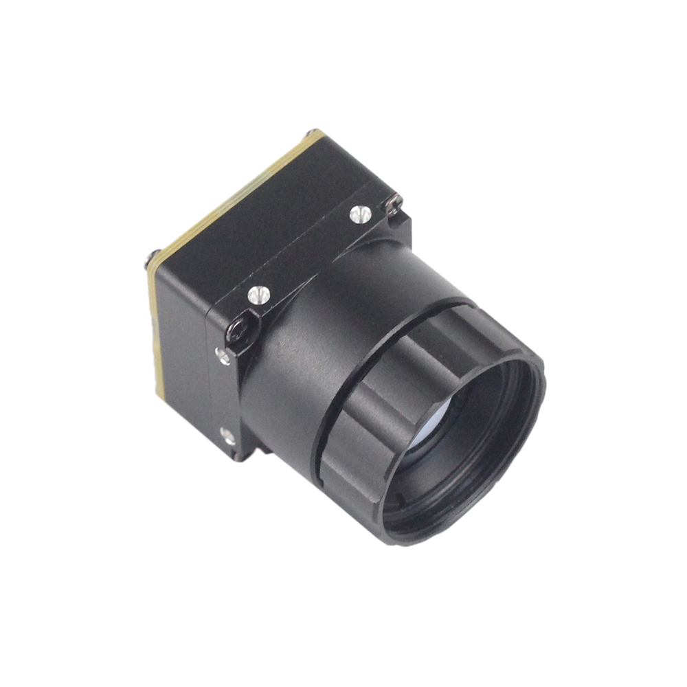
Moduł termowizyjny Mini2 640x512 9mm do dronów został zaprojektowany z myślą o instalacjach wrażliwych na wagę, gdzie każdy ułamek grama bezpośrednio skraca czas lotu. Ten kompaktowy rdzeń oferuje niesamowitą elastyczność konfiguracji, ponieważ posiada natywny fizyczny port USB Type-C (w pełni zgodny z klasą UVC) tuż obok surowego interfejsu MIPI CSI-2 na tej samej płycie.
Dzięki logice przetwarzania działającej natywnie na wbudowanym układzie ASIC, Mini2 renderuje wyjątkowo ostre, odszumione matryce termiczne. Jest zbudowany tak, aby izolować małe anomalie termiczne w siatkach poszukiwań i ratownictwa lub badaniach rolniczych, przebijając się przez dym, mgłę i całkowicie ciemne noce. Standardowy 9mm obiektyw germanowy zapewnia zoptymalizowane pole widzenia, które dobrze integruje się w dwusensorowych stabilizowanych gimbalach obok standardowych kamer wizyjnych z zoomem optycznym.
Wyświetl szczegóły produktu i ceny ➔
Szczegółowa analiza produktu 2: Niechłodzony termiczny rdzeń ASIC RJ45 CVBS RTSP IP 640*512

Podczas wdrażania sieci monitorujących w całej fizycznej fabryce, zakładzie chemicznym lub na długim obwodzie bezpieczeństwa, niechłodzony moduł ASIC RJ45 RTSP IP 640x512 to wytrzymałe rozwiązanie dalekiego zasięgu. Całkowicie omija ograniczenia długości kabla USB, osadzając pełną płytę interfejsu sieciowego na górze sensora obrazowego.
Wbudowany układ ASIC jest sprzętowo zoptymalizowany do dynamicznej kompresji i strumieniowania wartości z niechłodzonego mikrobolometru. Publikuje standardowe strumienie H.264 bezpośrednio w lokalnych sieciach IP za pomocą standardowych protokołów RTSP. Oznacza to, że można podłączyć kamerę bezpośrednio do istniejącego systemu zarządzania wideo (VMS) bez potrzeby dedykowanego komputera hosta znajdującego się tuż obok fizycznej kamery. Zbudowany wokół szczegółowej, niechłodzonej matrycy VOx 12µm, moduł ten zapewnia precyzyjną rozdzielczość przestrzenną i długoterminową dokładność diagnostyczną wymaganą do monitorowania infrastruktury.
Wyświetl szczegóły produktu i ceny ➔
FAQ inżynierii wizji przemysłowej
Ta techniczna sekcja FAQ odpowiada na głębokie wyzwania integracyjne, przed którymi stają architekci sprzętu i programiści systemów wbudowanych podczas wdrażania niechłodzonych mikrobolometrów.
Czy mogę uruchomić moduł kamery termowizyjnej UVC na Linuxie i Raspberry Pi bez zastrzeżonych SDK?
Jak obsługiwać pomiar danych temperatury termicznej przez UVC?
Czy istnieją opłacalne moduły termowizyjne UVC o wysokiej rozdzielczości do projektów wbudowanych?
Przewodnik integracji technicznej: Programowanie urządzeń UVC natywnie w C++ i Pythonie
Aby szybko przejść od prototypu sprzętowego do wdrożenia na skalę produkcyjną, deweloperzy mogą bezpośrednio podłączyć się do natywnych bibliotek wideo systemu. Poniższe szablony pokazują, jak łączyć się z niechłodzonymi systemami termowizyjnymi, aby pobierać klatki i wyodrębniać metadane bez polegania na zewnętrznych plikach binarnych prop-SDK.
Implementacja w Pythonie: Pozyskiwanie i normalizacja surowych strumieni termicznych Y16
Przed uruchomieniem skryptów potoku Pythona na docelowej płycie deweloperskiej upewnij się, że pakiety systemowe są zainstalowane:
sudo apt-get install python3-opencv python3-numpy v4l-utilsTen skrypt łączy się z Twoim Moduł kamery termowizyjnej UVC przez V4L2 i przechwytuje surowe 16-bitowe tablice monochromatyczne, przetwarzając każdą klatkę w celu wyświetlenia statystyk temperatury na żywo:
#!/usr/bin/env python3Implementacja w C++: Szybkie przechwytywanie klatek z niskim opóźnieniem przez Linux V4L2 i rdzeń OpenCV
W przypadku pętli przetwarzania o wysokiej częstotliwości, śledzenia szybko poruszających się celów powietrznych lub budowania wbudowanych potoków o niskim narzucie, natywny C++ zapewnia optymalną liczbę klatek na sekundę i minimalne obciążenie systemu. Aby skompilować aplikację, użyj następującego polecenia:
g++ -O3 main.cpp -o thermal_capture `pkg-config --cflags --libs opencv4`Poniżej znajduje się kod źródłowy potoku przechwytywania o niskim opóźnieniu:
#include <iostream>
#include <opencv2/opencv.hpp>
#include <opencv2/videoio.hpp>

// Explicitly define physical camera parameters
#define CAMERA_FPS 25
#define TARGET_WIDTH 640
#define TARGET_HEIGHT 512

int main() {
    // Instantiate raw capture driver context bound strictly via standard v4l2 backend
    cv::VideoCapture cap(0, cv::CAP_V4L2);

    if(!cap.isOpened()) {
        std::cerr << "Critical Error: Could not bind to target /dev/video0 interface!" << std::endl;
        return -1;
    }

    // Explicitly request video conversion bypass configuration
    // This allows the raw 16-bit pixel data array to pass untouched to the CPU memory
    cap.set(cv::CAP_PROP_CONVERT_RGB, 0);
    cap.set(cv::CAP_PROP_FRAME_WIDTH, TARGET_WIDTH);
    cap.set(cv::CAP_PROP_FRAME_HEIGHT, TARGET_HEIGHT);

    std::cout << "[SYSTEM ACTIVE] Stream started at resolution configuration: "
              << TARGET_WIDTH << "x" << TARGET_HEIGHT << " @ " << CAMERA_FPS << " FPS" << std::endl;

    cv::Mat rawFrame;
    cv::Mat normalized8Bit;
    cv::Mat colorizedOutput;

    while(true) {
        cap >> rawFrame;
        if(rawFrame.empty()) {
            std::cerr << "[WARNING] Latency dropped a buffer packet! Frame was empty." << std::endl;
            continue;
        }

        // OpenCV interprets raw, un-RGB-converted 16-bit Y16 thermal matrices as CV_16UC1 (1-channel 16-bit)
        // Convert to standard CV_8UC1 (1-channel 8-bit) using robust automatic calibration scaling
        double minVal, maxVal;
        cv::minMaxLoc(rawFrame, &minVal, &maxVal);

        // Normalize raw data dynamically to make the thermal details visible
        double scale = 255.0 / (maxVal - minVal);
        rawFrame.convertTo(normalized8Bit, CV_8UC1, scale, -minVal * scale);

        // Apply a highly dynamic Colormap rendering pipeline
        cv::applyColorMap(normalized8Bit, colorizedOutput, cv::COLORMAP_INFERNO);

        // Render crosshairs at the center pixel location to track spatial temperature trends
        int centerX = TARGET_WIDTH / 2;
        int centerY = TARGET_HEIGHT / 2;

        // Grab the raw value at the crosshair and convert to representative temp
        uint16_t centerRawVal = rawFrame.at<uint16_t>(centerY, centerX);
        double centerTempCelsius = (centerRawVal / 100.0) - 273.15;

        // Print center temperature value directly onto screen buffer rendering
        std::string labelText = "Center Temp: " + std::to_string(centerTempCelsius).substr(0, 5) + " C";
        cv::putText(colorizedOutput, labelText, cv::Point(20, 40),
                    cv::FONT_HERSHEY_COMPLEX_SMALL, 1.0, cv::Scalar(255, 255, 255), 2);

        // Draw crosshair overlay
        cv::line(colorizedOutput, cv::Point(centerX - 10, centerY), cv::Point(centerX + 10, centerY), cv::Scalar(0, 255, 0), 2);
        cv::line(colorizedOutput, cv::Point(centerX, centerY - 10), cv::Point(centerX, centerY + 10), cv::Scalar(0, 255, 0), 2);

        // Draw dynamic view portal on active screen
        cv::imshow("Embedded Linux Thermal Vision Terminal Portal", colorizedOutput);

        // Press 'q' or ESC (ASC-II Code 27) to break the capture loop
        char keyPress = (char)cv::waitKey(1);
        if (keyPress == 'q' || keyPress == 27) {
            break;
        }
    }

    cap.release();
    cv::destroyAllWindows();
    std::cout << "[SYSTEM CLOSE] Hardware channel freed. Terminating program operations." << std::endl;
    return 0;
}
Praktyki kalibracji i utrzymania jednorodności
Korekcja płaskiego pola (FFC / Kalibracja migawki)
Ponieważ niechłodzone mikrobolometry są bardzo wrażliwe na gradienty termiczne wewnątrz samej obudowy kamery, dryft obrazu może narastać podczas dłuższych okresów pracy. Ten dryft termiczny objawia się jako przestrzenny szum wzorcowy w cyfrowym buforze ramki, co pogarsza dokładność pomiaru i jakość obrazu.
Aby to skorygować, niechłodzone rdzenie kamer wykorzystują automatyczny lub ręczny cykl programowy zwany korekcją płaskiego pola (FFC). Podczas cyklu FFC mechaniczna migawka (zwykle mała, nieogrzewana, jednolita płytka) opada na ułamek sekundy przed niechłodzoną matrycą czujnika mikrobolometrycznego. Wewnętrzny procesor kamery odczytuje ten idealnie płaski cel termiczny i resetuje wszelkie dryfujące przesunięcia pikseli z powrotem do jednolitej linii bazowej. Zapewnia to, że odczyty temperatury i jakość obrazu pozostają spójne i dokładne przez długi czas użytkowania.
Niestandardowe wyzwalacze programowej migawki
Chociaż automatyczna FFC domyślnie działa samodzielnie, to zdarzenie migawki zatrzymuje strumień wideo na około 200–500 milisekund. W zastosowaniach o wysokiej stawce — takich jak śledzenie celów z szybkiego drona lub lądowanie pojazdu autonomicznego — to nagłe zatrzymanie może przerwać krytyczne operacje.
Aby to rozwiązać, programiści mogą używać niestandardowych nadpisań oprogramowania. Używając jednostek rozszerzeń UVC (XU) do programowego wyzwalania cyklu FFC przez magistralę USB, projektanci mogą wyłączyć automatyczny wewnętrzny licznik czasu. Pozwala to systemowi odroczyć kalibrację do dogodniejszego momentu, na przykład gdy dron unosi się bezpiecznie lub gdy analityczne pętle obliczeniowe są tymczasowo wstrzymane. Takie podejście zapewnia nieprzerwane wideo, gdy wydajność ma kluczowe znaczenie.
Zalecenia dotyczące projektowania architektonicznego
- ✅ Aby zapoznać się z naszym pełnym katalogiem inżynieryjnym zaawansowanych niechłodzonych celów czujników termicznych dalekiego zasięgu, rdzeni na płytkach drukowanych i przemysłowych zestawów analitycznych, dodaj do zakładek naszą główną Centrum blogów o obrazowaniu termicznym.
- ✅ W przypadku szczegółowych niestandardowych zapytań, schematów wyprowadzeń, konkretnych kombinacji obiektywów lub dokumentów wsparcia SDK dla programistów, skontaktuj się bezpośrednio z naszym działem wsparcia inżynieryjnego pod adresem Strona produktów Purpleriver aby ożywić swoje wbudowane projekty wizji maszynowej.
📚 Piśmiennictwo i dalsze lektury
- Standard branżowy: Przewodniki po ładunkach OBSETECH | Standardy integracji systemu na chipie JM Chip
- Powiązany przewodnik: Jak bez wysiłku wykrywać usterki transformatorów: Przewodnik po obrazowaniu termicznym