








MIPI Thermal Camera Module Guide: High-Res Edge AI Integration for Raspberry Pi & Drones
2026年7月20日
CMOS Sensor Thermal Camera Module: Integration Guide & OEM Solutions
2026年7月21日
Top UVC Thermal Camera Modules for Linux, Pi & Embedded Systems
If you're in the trenches building hardware—whether you're a system integrator, a drone developer rigging up autonomous payloads, or an industrial automation engineer—you already know the score. The real bottleneck in deploying Long-Wave Infrared (LWIR) sensing isn't the physical sensor resolution anymore. The actual headache is what I call the "SDK tax." Traditional thermal core modules are notorious for requiring closed-source kernel drivers, platform-locked binaries, and convoluted, proprietary software pipelines. Try getting those to play nice with a custom Linux distro, a modern Robot Operating System environment (ROS 1 or ROS 2), or an energy-constrained Raspberry Pi, and you'll quickly find yourself in integration hell. It burns engineering hours, delays your time-to-market, and introduces massive vulnerabilities to your edge computing setup.
Here's the deal: standard USB Video Class (UVC) thermal camera modules change the game entirely. By mapping uncooled LWIR microbolometer sensors directly to the native USB video protocol, these modules expose thermal imaging feeds directly to your operating system's built-in drivers. We're talking Video4Linux2 (V4L2) on Linux and standard DirectShow/MediaFoundation APIs on Windows. It's pure plug-and-play. You can grab raw radiometric or YUV data streams right out of the box, dropping your software integration overhead to near zero, freeing up critical onboard CPU cycles, and making Edge AI deployment actually practical. This guide is a complete, battle-tested design blueprint for selecting, configuring, and programming high-performance uncooled UVC and raw digital thermal camera modules in embedded Linux ecosystems.
Table of Contents
- 👉 1. What is a Native UVC Thermal Camera Module?
- 👉 2. UVC USB-C vs. MIPI CSI-2 vs. Networks (RJ45 IP Streams)
- 👉 3. V4L2 Driver Architecture, ROS Integration, and Raspberry Pi Configurations
- 👉 4. Decoding the Stream: Decoupling Visual Grayscale from Raw Radiometric Matrices
- 👉 5. Optical Microbolometer Dynamics: Pixel Pitch (12µm vs. 17µm) and Spectral Response
- 👉 6. Industrial Product Profiles & Real Performance Parameters
- 👉 7. C++ & Python Driver Implementations for Embedded Linux Platforms
- 👉 8. Deep-Dive Engineering FAQ
Understanding UVC Thermal Camera Modules
Broadening Embedded Horizons: What Is a UVC Thermal Camera Module?
When you boil it down, a UVC thermal camera module is simply an uncooled infrared sensor paired with an onboard digital backend that speaks the language of standard USB-IF UVC parameters. Unlike typical consumer thermal options that force you to run proprietary software wrappers, a UVC core acts exactly like a standard webcam. It hooks into the host operating system with zero fuss, making it a reliable, cross-platform choice for serious industrial projects.
Let's look under the hood. The whole process starts at the optics. Long-Wave Infrared radiation (typically hanging out in the 8µm to 14µm spectral bandwidth) passes through a specialized chunk of Germanium—glass doesn't cut it here—and focuses onto an array of microbolometers. These microbolometers are usually made of Vanadium Oxide (VOx) or Amorphous Silicon (a-Si). When the infrared radiation hits them, they change resistance based on their temperature. This change is sampled by an onboard Analog-to-Digital Converter (ADC) and converted into raw digital value registers, usually at 14-bit or 16-bit depth.
Next, an onboard ASIC or DSP takes care of the heavy lifting. It runs critical, real-time corrections like Non-Uniformity Correction (NUC), Bad Pixel Replacement (BPR), and Automatic Gain Control (AGC). Then, instead of dumping this processed data over a custom parallel bus, the ASIC packages it up as standard, UVC-compliant USB video packets. Whether you connect via USB-C, micro-USB, or a rugged board-to-board JST connector, the device streams direct to the host processor's memory registers using the OS's native drivers.
In the shop, the biggest win here is reliability. If you do a regular kernel update on an Ubuntu or Debian system, it’s not going to break your sensor pipeline. This is huge when you’re building complex, critical machinery like uncrewed aerial vehicles (UAVs) where the companion computer is running a real-time OS patch like PREEMPT_RT. Because the camera’s built-in processor handles the ugly correction math—NUC, defect replacement, and dynamic range compression—your host CPU doesn't break a sweat, leaving its cycles free for computer vision, path planning, or neural networks.
Hardware Interface Showdown: UVC USB-C vs. MIPI CSI-2 vs. RJ45 RTSP/IP Streamers
Evaluating Physical Interconnects
Choosing the right physical connection will draw the boundaries for your entire design—it locks in your max framerates, resolution limits, system latency, and how far you can run your cables. When you're sitting at the CAD station drafting up a thermal capture setup, you generally find yourself looking at three physical options: USB, MIPI CSI-2, or flat-out RJ45 ethernet streaming.
UVC USB Interface
In the shop, we love standard USB pipelines because they make our lives incredibly easy. Over a physical USB 2.0 or 3.0 interface (usually a native Type-C or board-to-board JST connector), the module exposes itself using basic, predictable USB video descriptors. It requests bulk or isochronous endpoints and pumps out clean, raw YUYV, MJPEG, or monochrome digital streams. No compiling custom kernel drivers, no fighting weird source setups—it just works.
The only real catch here is physical routing. Standard USB high-speed differential pairs can't run long distances without signal degradation, and they're highly sensitive to electromagnetic interference (EMI). If you're designing layout arrays inside a high-power drone frame with high-kV ESCs, or near beefy industrial servo drives, you need to shield your USB lines carefully. Still, for close-coupled systems like head-mounted displays, hand-held monitors, and compact edge devices, USB-UVC is overwhelmingly the path of least resistance.
MIPI CSI-2 Interface
If you're squeezing every microsecond out of your pipeline, MIPI CSI-2 is the heavy hitter. It pipes raw, uncompressed microbolometer data directly into your CPU's hardware-level Image Signal Processor (ISP). We're talking absolute minimum latency, with frames landing directly in memory buffers via DMA. It's the standard choice for professional, stabilized drone gimbals where flight control loops depend on optical flow or visual tracking.
But be warned: the development cost is steep. MIPI CSI-2 is not plug-and-play. It lacks self-describing descriptors. You’ll have to develop your own custom Board Support Packages (BSP) and device-tree overlays, plus route high-speed differential lanes with strict trace-length matching and impedance target constraints on your PCB. If you're prototyping or building low-to-medium volume systems, MIPI can turn into a serious engineering bottleneck.
RJ45 Networking (RTSP/IP Modules)
When you need to send a video stream across a facility, you want a networked setup. These modules integrate an additional video compression ASIC on the board itself, packing the thermal frames into standard H.264 or H.265 streams delivered over RTSP, RTMP, or ONVIF protocols. You can run Cat6 ethernet cables up to 100 meters without a single repeater—perfect for setting up perimeter security, substation monitors, or structural monitoring arrays.
Excellent networked system-on-chip solutions tailored for these environments are widely developed by specialized hardware suppliers like JM Chip. However, keep in mind that encoding the frames on-sensor adds compression latency, and decoding the stream on the other end burns CPU cycles on your destination machine, making it less suitable for high-speed dynamic tracking or raw, low-latency control loops.
Linux Kernel & V4L2: Pure Plug-and-Play Driver Architecture for Raspberry Pi and ROS
On modern ARMv7 and ARMv8 embedded Linux boards—such as the Broadcom BCM2711/BCM2712 powering the Raspberry Pi 4 and 5—the Linux kernel automatically loads the standard uvcvideo module the moment you hook up the device. That camera maps cleanly to /dev/videoX.
Let's map out this software architecture. Under the hood, the raw physical UVC thermal core connects via USB. The kernel's native uvcvideo driver intercepts it, instantly exposing it to V4L2 (Video4Linux2). This populates node devices at /dev/videoX, allowing downstream frameworks—like ROS 1's usb_cam node or ROS 2's v4l2_camera container—to grab streams flawlessly. You end up with standard visual topics (like /thermal/image_raw) ready for down-the-line vision tasks or high-fidelity 16-bit matrices ready for automated scripts.
If you're running Robot Operating System (ROS 1 or ROS 2) architectures, you can bind standard driver nodes directly to the device path and start publishing standard image topics (sensor_msgs/Image). To query or configure device parameters (like frame rates, target resolutions, or gain modes) dynamically without writing code, use the standard command-line tools in the terminal:
# Query system-registered V4L2 USB devices
v4l2-ctl --list-devices

# View pixel stream formats supported by the connected thermal module
v4l2-ctl -d /dev/video0 --list-formats-ext
In multi-sensor robotic setups, this native architecture eliminates structural headaches. You don't have to worry about third-party SDK dependencies clashing with your workspace. You can use V4L2 IOCTL commands directly in your code to alter camera exposure bias, cycle pseudo-color overlays, or switch between high and low gain modes on-the-fly. For rugged drone implementations or outdoor integrations, you can also see trace configurations implemented by operators like OBSETECH who specialize in deploying high-performance payload cameras under tough, uncooperative outdoor conditions.
Decoding the Stream: Visual YUV Frame Buffer vs. Raw Radiometric Temperature Data
While a UVC thermal module streams standard-looking webcam packets (using familiar pixel formats like MJPEG, YUYV, or RGB24), you need to understand that the output data stream can represent two entirely different pipelines depending on your development requirements.
1. Visual Color-Mapped Streams (YUYV/MJPEG)
In this mode, the camera's onboard DSP takes the raw, high-fidelity thermal information and converts it down to an 8-bit visual scale (0 to 255 values, often colorized using standard palettes like Ironbow, Rainbow, or raw Grayscale). This stream is what you want if you are displaying a live image for a human screen, building a mobile monitor, or feeding a visual deep neural network (like running YOLO or proprietary inference models to identify humans or machinery in pitch darkness).
The catch? You lose the actual raw temperature data. Because the onboard processor continuously scales the contrast to make the image clear to human eyes, a pixel value of 150 on the screen does not represent a static, absolute temperature. If you need to map precise temperature trends, visual streams won't cut it.
2. Raw Radiometric Streams (Y16 / 14-Bit Monochromatic)
To pull actual, absolute physical temperatures, you need to configure your V4L2 pipeline to capture uncompressed Y16 raw frames. In this mode, every pixel is delivered as a raw 14-bit or 16-bit Digital Number (DN) mapping directly to the micro-voltage variations of the microbolometer.
By requesting Y16, you turn every pixel on the array into a calibrated, contact-free thermometer. Assuming your core module has been calibrated at the factory, your software applies a linear equation to translate this raw digital map:
To convert this raw sensor data into standard Celsius units, you can apply the following calculation to each pixel in python or C++:
Bottom line? If you are building automated thermal inspection loops, you must read raw Y16 frames. Letting high-level media libraries touch the stream will mangle your data with lossy compression or smoothing filters, corrupting your thermal calibration matrices. For a practical look at how these calibrated matrices can check physical targets—like keeping high-voltage power networks safe—check out our technical guide: How to Detect Transformer Faults Effortlessly: Thermal Imaging Guide.
Optical Microbolometer Dynamics: Pixel Pitch and Spectral Response
When selecting and integrating uncooled microbolometers, two main variables determine spatial recognition limits: the microbolometer array's pixel pitch and the optical focal length of its Germanium lens assembly.
Pixel Pitch (12µm vs. 17µm)
Modern micro-cores leverage uncooled Vanadium Oxide (VOx) or Amorphous Silicon (a-Si) sensor matrices. While older designs relied on a larger 17µm pixel pitch, modern cores leverage a tighter 12µm pixel pitch. This reduction in pixel pitch delivers a major engineering advantage: it decreases the physical footprint of the sensor array while maintaining the exact same resolution.
Consequently, a 12µm core can achieve the identical Field of View (FOV) of a 17µm sensor while using a smaller, lighter, and more cost-effective Germanium optical lens. At the same time, the reduced thermal mass of each individual sensor element on a 12µm pitch chip lowers thermal noise, yielding a highly competitive Noise Equivalent Temperature Difference (NETD) of under 40mK or 50mK.
Optomechanical Calculations
Field layouts are determined by calculating the spatial resolution, also known as the Instantaneous Field of View (IFOV). Calculate the theoretical pixel footprint with the following formula:
Where d is the physical pixel pitch and f is the optical focal length of the Germanium lens. To compute the horizontal Field of View (HFOV) for a 640 x 512 array using a 9mm lens package on a 12µm pitch core:
HFOV = 2 * arctan(Array Width / (2 * f)) = 2 * arctan(7.68 / 18) ≈ 46.2°
By utilizing a 12µm architecture combined with a 9mm target focus, system developers can deploy wide-angle thermal vision systems in highly restricted physical envelopes, making it ideal for compact multi-sensor drone gimbals. If manual mobile target-acquisition or long-range reconnaissance is required over raw embedded PCB modules, read-up on physical portable scopes inside our catalog detailing Wholesale Night Reconnaissance Infrared Binoculars.
Industrial Product Profiles & Real Performance Parameters
Engineers designing industrial monitoring systems, agricultural drones, and automated security grids require deeply documented technical specifications. The following comprehensive comparison highlights two cutting-edge uncooled thermal core designs available in our direct manufacturing catalog:
⚙️ **Product 1:** Uncooled Infrared Mini2 640x512/384x288/256x192 9mm MIPI & UVC-Enabled Thermal Imaging Camera Module (designed for weight-constrained aerial systems).
⚙️ **Product 2:** Uncooled Infrared RJ45 CVBS RTSP IP 640x512 ASIC Thermal Sensor Camera Module (built for networked facility monitors and security integration).
Product Deep-Dive 1: Uncooled Infrared Mipi 640/384/256 9mm For Drones

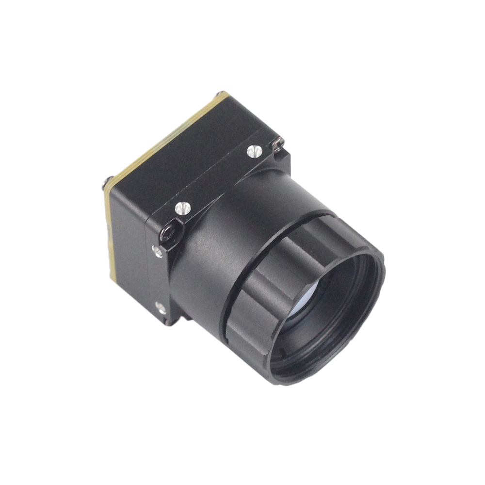
The Mini2 640x512 9mm Drone Thermal Module is built for weight-sensitive setups where every fraction of a gram cuts directly into flight time. This compact core gives you incredible configuration flexibility because it offers a native USB Type-C physical port (fully UVC class compliant) right alongside a raw MIPI CSI-2 interface on the same board assembly.
With processing logic running natively on its onboard ASIC, the Mini2 renders exceptionally crisp, noise-filtered thermal matrices. It's built to isolate small thermal anomalies in search-and-rescue grids or agricultural surveys, cutting through smoke, fog, and pitch-black nights. The standard 9mm Germanium lens provides an optimized Field of View that integrates nicely into dual-sensor stabilized gimbals alongside standard optical visual zoom cameras.
View Product Details & Pricing ➔
Product Deep-Dive 2: Uncooled RJ45 CVBS RTSP IP 640*512 ASIC Thermal Core

When you're deploying monitoring networks across a physical factory, chemical plant, or long security perimeter, the Uncooled RJ45 RTSP IP 640x512 ASIC Module is the ruggedized, long-range solution. It completely sidesteps the cable length limits of USB by embedding a full network-enabled interface board on top of the imaging sensor.
The onboard ASIC is hardware-optimized to compress and stream uncooled microbolometer values dynamically. It publishes standard H.264 streams directly over local IP networks via standard RTSP protocols. This means you can hook the camera straight into your existing Video Management System (VMS) without needing a dedicated host PC sitting right next to the physical camera. Built around a detailed 12µm uncooled VOx matrix, this module provides the precise spatial resolution and long-term diagnostic accuracy needed for infrastructure monitoring.
View Product Details & Pricing ➔
Industrial Vision Engineering FAQ
This technical FAQ section addresses the deep integration challenges faced by hardware architects and embedded software developers when deploying uncooled microbolometers.
Can I run a UVC thermal camera module on Linux and Raspberry Pi without proprietary SDKs?
How do I handle thermal temperature data measurement over UVC?
Are there cost-effective, high-resolution UVC thermal modules for embedded projects?
Technical Integration Guide: Programming UVC Devices Natively in C++ and Python
To transition quickly from hardware prototype to production-grade deployment, developers can hook directly into native system video libraries. The following templates show how to interface with uncooled thermal systems to pull frames and extract metadata without relying on external prop-SDK binaries.
1. Python Implementation: Acquiring and Normalizing Raw Y16 Thermal Streams
Before running the python pipeline scripts on your target development board, ensure the system packages are installed:
sudo apt-get install python3-opencv python3-numpy v4l-utilsThis script binds to your uvc thermal camera module over V4L2 and captures raw 16-bit monochromatic arrays, processing each frame to display live temperature statistics:
#!/usr/bin/env python3
import cv2
import numpy as np
import sys

def main():
    # Attempt to open the first UVC device system index
    # We enforce the CAP_V4L2 backend to bypass high-level media-framework intervention
    v4l2_device_index = 0
    cap = cv2.VideoCapture(v4l2_device_index, cv2.CAP_V4L2)

    if not cap.isOpened():
        print(f"Error: Critical interface failure opening video device node '/dev/video{v4l2_device_index}'.")
        sys.exit(1)

    # Program V4L2 parameters to request raw 16-bit uncompressed Y16/YUYV streams
    # Many thermal sensors output a native 14-bit depth packet wrapped within a Y16 container
    cap.set(cv2.CAP_PROP_CONVERT_RGB, 0)

    # Request our target native layout resolutions matching the hardware sensor specs
    target_width = 640
    target_height = 512
    cap.set(cv2.CAP_PROP_FRAME_WIDTH, target_width)
    cap.set(cv2.CAP_PROP_FRAME_HEIGHT, target_height)

    print(f"UVC Thermal Stream successfully initialized at {target_width}x{target_height}")
    print("Press the 'ESC' key over the focus frame buffer window to safely terminate runtime loops...")

    try:
        while True:
            ret, frame = cap.read()
            if not ret or frame is None:
                print("Warning: Failed to capture frame from the UVC bus stream.")
                continue

            # Treat incoming raw frame buffer directly as 16-bit array mapping
            # This represents the linear response of each physical pixel on the microbolometer
            raw_16bit_frame = frame.view(dtype=np.uint16).reshape((target_height, target_width))

            # Absolute Temperature Formula Example:
            # Let's assume a standard 100x magnification calibration factor (e.g., Temp = raw_val / 100)
            # This formula returns absolute Celsius values with high precision.
            temperature_matrix_c = (raw_16bit_frame / 100.0) - 273.15

            # Calculate simple spatial statistics across our thermal array
            min_temp = np.min(temperature_matrix_c)
            max_temp = np.max(temperature_matrix_c)
            avg_temp = np.mean(temperature_matrix_c)

            # Normalize the 16-bit raw array down to 8-bit grayscale for display
            normalized_8bit = cv2.normalize(raw_16bit_frame, None, 0, 255, cv2.NORM_MINMAX, dtype=cv2.CV_8U)

            # Apply a pseudo-color map to make the thermal distribution highly visible
            colorized_thermal_render = cv2.applyColorMap(normalized_8bit, cv2.COLORMAP_JET)

            # Render key monitoring metrics on the visual display overlay
            overlay_text = f"Temp Scope: Min={min_temp:.1f}C | Max={max_temp:.1f}C | Avg={avg_temp:.1f}C"
            cv2.putText(colorized_thermal_render, overlay_text, (15, 30),
                        cv2.FONT_HERSHEY_SIMPLEX, 0.6, (255, 255, 255), 2, cv2.LINE_AA)

            # Draw thermal visualization to active desktop screen
            cv2.imshow("Industrial Thermal Analytics Portal", colorized_thermal_render)

            # Check for Esc key press (ASC-II Code 27)
            key = cv2.waitKey(1) & 0xFF
            if key == 27:
                break

    finally:
        # Guarantee physical port release and destroy open render windows
        cap.release()
        cv2.destroyAllWindows()
        print("UVC Stream successfully closed. System exited cleanly.")

if __name__ == "__main__":
    main()
2. C++ Implementation: Fast Low-Latency Frame Capture via Linux V4L2 and OpenCV Core
For high-frequency processing loops, tracking fast-moving airborne targets, or building low-overhead embedded pipelines, native C++ provides optimal frame rates and minimal system overhead. To compile the application, use the following command:
g++ -O3 main.cpp -o thermal_capture `pkg-config --cflags --libs opencv4`Below is the low-latency capture pipeline source code:
#include <iostream>
#include <opencv2/opencv.hpp>
#include <opencv2/videoio.hpp>

// Explicitly define physical camera parameters
#define CAMERA_FPS 25
#define TARGET_WIDTH 640
#define TARGET_HEIGHT 512

int main() {
    // Instantiate raw capture driver context bound strictly via standard v4l2 backend
    cv::VideoCapture cap(0, cv::CAP_V4L2);

    if(!cap.isOpened()) {
        std::cerr << "Critical Error: Could not bind to target /dev/video0 interface!" << std::endl;
        return -1;
    }

    // Explicitly request video conversion bypass configuration
    // This allows the raw 16-bit pixel data array to pass untouched to the CPU memory
    cap.set(cv::CAP_PROP_CONVERT_RGB, 0);
    cap.set(cv::CAP_PROP_FRAME_WIDTH, TARGET_WIDTH);
    cap.set(cv::CAP_PROP_FRAME_HEIGHT, TARGET_HEIGHT);

    std::cout << "[SYSTEM ACTIVE] Stream started at resolution configuration: "
              << TARGET_WIDTH << "x" << TARGET_HEIGHT << " @ " << CAMERA_FPS << " FPS" << std::endl;

    cv::Mat rawFrame;
    cv::Mat normalized8Bit;
    cv::Mat colorizedOutput;

    while(true) {
        cap >> rawFrame;
        if(rawFrame.empty()) {
            std::cerr << "[WARNING] Latency dropped a buffer packet! Frame was empty." << std::endl;
            continue;
        }

        // OpenCV interprets raw, un-RGB-converted 16-bit Y16 thermal matrices as CV_16UC1 (1-channel 16-bit)
        // Convert to standard CV_8UC1 (1-channel 8-bit) using robust automatic calibration scaling
        double minVal, maxVal;
        cv::minMaxLoc(rawFrame, &minVal, &maxVal);

        // Normalize raw data dynamically to make the thermal details visible
        double scale = 255.0 / (maxVal - minVal);
        rawFrame.convertTo(normalized8Bit, CV_8UC1, scale, -minVal * scale);

        // Apply a highly dynamic Colormap rendering pipeline
        cv::applyColorMap(normalized8Bit, colorizedOutput, cv::COLORMAP_INFERNO);

        // Render crosshairs at the center pixel location to track spatial temperature trends
        int centerX = TARGET_WIDTH / 2;
        int centerY = TARGET_HEIGHT / 2;

        // Grab the raw value at the crosshair and convert to representative temp
        uint16_t centerRawVal = rawFrame.at<uint16_t>(centerY, centerX);
        double centerTempCelsius = (centerRawVal / 100.0) - 273.15;

        // Print center temperature value directly onto screen buffer rendering
        std::string labelText = "Center Temp: " + std::to_string(centerTempCelsius).substr(0, 5) + " C";
        cv::putText(colorizedOutput, labelText, cv::Point(20, 40),
                    cv::FONT_HERSHEY_COMPLEX_SMALL, 1.0, cv::Scalar(255, 255, 255), 2);

        // Draw crosshair overlay
        cv::line(colorizedOutput, cv::Point(centerX - 10, centerY), cv::Point(centerX + 10, centerY), cv::Scalar(0, 255, 0), 2);
        cv::line(colorizedOutput, cv::Point(centerX, centerY - 10), cv::Point(centerX, centerY + 10), cv::Scalar(0, 255, 0), 2);

        // Draw dynamic view portal on active screen
        cv::imshow("Embedded Linux Thermal Vision Terminal Portal", colorizedOutput);

        // Press 'q' or ESC (ASC-II Code 27) to break the capture loop
        char keyPress = (char)cv::waitKey(1);
        if (keyPress == 'q' || keyPress == 27) {
            break;
        }
    }

    cap.release();
    cv::destroyAllWindows();
    std::cout << "[SYSTEM CLOSE] Hardware channel freed. Terminating program operations." << std::endl;
    return 0;
}
Calibration & Uniformity Maintenance Practices
Flat Field Correction (FFC / Shutter Calibration)
Because uncooled microbolometers are highly sensitive to thermal gradients within the camera chassis itself, image drift can accumulate over extended runtime periods. This thermal drift manifests as spatial pattern noise across the digital frame buffer, which degrades measurement accuracy and visual quality.
To correct this, uncooled camera cores use an automated or manual program cycle called Flat Field Correction (FFC). During an FFC cycle, a mechanical shutter (usually a small, unheated uniform plate) drops in front of the uncooled microbolometer sensor array for a split second. The camera's internal processor reads this perfectly flat thermal target and resets any drifting pixel offsets back to a uniform baseline. This ensures that your temperature readings and image quality remain consistent and accurate over long periods of use.
Custom Software Shutter Triggers
While auto-FFC runs on its own by default, this shutter event freezes the video stream for about 200–500 milliseconds. In high-stakes applications—like tracking targets from a high-speed drone or landing an autonomous vehicle—this sudden freeze can interrupt critical operations.
To solve this, developers can use custom software overrides. By using UVC Extension Units (XUs) to trigger the FFC cycle programmatically over the USB bus, designers can suppress the automatic internal timer. This allows the system to defer calibration until a more convenient time, such as when a drone is hovering safely or when analytical computational loops are temporarily paused. This approach ensures uninterrupted video when performance is critical.
Architectural Design Recommendations
- ✅ To explore our complete engineering catalog of advanced long-range uncooled thermal sensor targets, bare-board cores, and industrial analytics assemblies, bookmark our primary Thermal-Image Blog Hub.
- ✅ For deep-dive custom requests, pin-out schematics, specific lens combinations, or developer SDK support documents, contact our engineering support desk directly at Purpleriver Products Page to bring your embedded machine vision projects to life.
📚 References & Further Reading
- Industry Standard: OBSETECH Payload Guides | JM Chip System-On-Chip Integration Standards
- Related Guide: How to Detect Transformer Faults Effortlessly: Thermal Imaging Guide





