Industrial USB Thermal Camera Core: Compact LWIR OEM Modules for Embedded Vision & Inspection
2026年9月20日
Analog Thermal Camera Core Guide: Low-Latency CVBS Modules for FPV, DIY Optics & OEM
2026年9月23日

# Best CVBS Thermal Camera Module: Low-Latency Analog Cores for Drones & Systems
In uncrewed aerial vehicles (UAVs), tactical robotics, and high-speed industrial automation, video transmission latency is often the primary point of system failure. Modern network video infrastructure leans heavily toward digital IP configurations, high-definition streaming protocols, and software-defined pipelines. Yet these architectures introduce systemic frame serialization, buffering, and packetization latency that runs anywhere from 80 milliseconds to upwards of 250 milliseconds under actual operational field conditions. For high-speed first-person view (FPV) piloting, agile target-tracking gimbals, edge guidance platforms, and closed-loop collision avoidance, this processing lag leads directly to catastrophic dynamic overshoot, pilot disorientation, and tracking loop divergence. The **CVBS thermal camera module** bypasses digital network encapsulation overhead entirely. It outputs raw, analog baseband composite video (PAL or NTSC) straight from the sensor’s dedicated Application-Specific Integrated Circuit (ASIC). This deterministic pipeline provides the true near-zero-latency imaging required for split-second tactical decisions and continuous closed-loop control.
Selecting the right analog infrared imaging core requires balancing subtle trade-offs across thermal sensitivity, sensor resolution, Size, Weight, and Power (SWaP) constraints, and complex electrical integration parameters. An industrial-grade thermal core must reliably bridge the sensitive microbolometer detector array to standard 75-ohm coaxial lines. At the same time, it must execute Non-Uniformity Correction (NUC), Digital Detail Enhancement (DDE), dynamic range compression, and digital-to-analog conversion on-chip with absolute thermal stability. This comprehensive engineering guide breaks down the underlying physics and signal conditioning of composite video thermal cores, outlines integration workflows for airborne FPV transmitters and industrial programmable logic controller (PLC) monitors, and benchmarks industry-leading uncooled long-wave infrared (LWIR) cores.
Spis treści
- 👉 Engineering Fundamentals: What is a CVBS Thermal Camera Module?
- 👉 Critical Engineering Metrics: Latency, SWaP-C, NETD, and Resolution
- 👉 Product Showcase: Industrial-Grade CVBS Thermal Cores
- 👉 Airborne System Architecture: Integrating CVBS Cores into Drones and FPV Links
- 👉 Automotive, Robotics, and Industrial Monitoring Deployments
- 👉 Interface Showdown: CVBS vs. MIPI-CSI2 vs. USB vs. RJ45 IP
- 👉 Frequently Asked Questions (FAQ)
Engineering Fundamentals: What is a CVBS Thermal Camera Module?
A CVBS (Composite Video Blanking and Sync) thermal camera module is a self-contained long-wave infrared (LWIR) electro-optical engine that captures passive thermal radiation emitted within the 8 to 14 micrometer (μm) atmospheric transmission window. It converts these photon fluxes internally into an analog baseband television signal conforming to standard CCIR/PAL or EIA/NTSC timing protocols. The signal is driven across a single unbalanced conductor, terminated into a 75-ohm characteristic impedance at a standard amplitude of 1.0 volt peak-to-peak (1.0 Vp-p).
The underlying physical pipeline relies on an uncooled microbolometer detector array. These focal plane arrays (FPAs) are micromachined from Vanadium Oxide (VOx) or Amorphous Silicon (α-Si) thin films suspended on micro-bridges above a silicon Readout Integrated Circuit (ROIC) substrate. As incident LWIR photons pass through a specialized Germanium or Chalcogenide optical lens assembly, they strike the thermally isolated microbolometer membrane pixels. The absorption of this radiative thermal energy induces a measurable change in the bulk electrical resistance of the material, governed by its Temperature Coefficient of Resistance (TCR). The underlying ROIC measures these minute resistance variations pixel by pixel, integrating electrical charges and converting them via high-precision on-chip analog-to-digital converters into raw 14-bit or 16-bit digital thermal values.
In standard IP-based digital thermal cameras, this high-bit-depth raw digital stream travels through an image signal processor (ISP), is handed over to a microprocessor running an embedded operating system, compressed via computational H.264 or H.265 video codecs, fragmented into network transport packets, and transmitted across an Ethernet physical layer (PHY) using Real-Time Streaming Protocol (RTSP) over UDP/IP. This processing chain incurs substantial processing latency, frame jitter, and memory buffer allocations, easily accumulating hundreds of milliseconds of real-time delay.
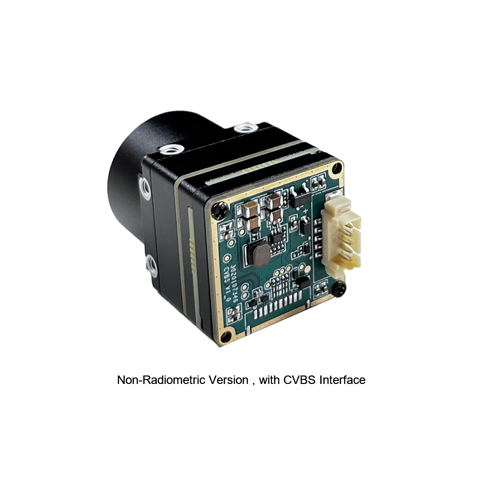
A dedicated CVBS thermal core avoids this overhead entirely by deploying a streamlined, hardware-level signal conversion architecture:
First, the uncompressed 14-bit raw digital matrix from the ROIC enters an ultra-fast hardware ASIC or Field-Programmable Gate Array (FPGA). This processing core immediately applies hardware-accelerated calibration algorithms: two-point Non-Uniformity Correction (NUC), bad pixel replacement, blind pixel suppression, and spatial noise filtering. These operations strip away sensor-level fixed-pattern noise caused by semiconductor manufacturing variations and ambient detector temperature drift.
Second, the wide dynamic range of the 14-bit thermal data (which represents thousands of discrete temperature steps) must be translated for human observation or analog transmission. The ASIC runs advanced Digital Detail Enhancement (DDE) and dynamic plateau histogram equalization algorithms. These routines preserve local high-frequency spatial details (such as thin structural edges, power lines, and subtle target contours) while compressing the global thermal scene into an optimized 8-bit dynamic envelope. This data is mapped in real time to selectable grayscale or color palettes, such as White-Hot, Black-Hot, Ironbow, or specialized pseudo-color scales.
Third, instead of routing this 8-bit frame to a digital compression engine, the processed stream feeds directly into an onboard high-speed Digital-to-Analog Converter (DAC) paired with an analog video line driver. The video driver generates precise, hardware-timed synchronization pulses, blanking intervals, front and back porches, and active video lines conforming directly to analog video raster specifications:
* ⚙️ **PAL Specification:** 625 total lines, 50 fields per second (25 frames per second interlaced), 15.625 kHz horizontal line frequency, with a color subcarrier at 4.433618 MHz if chrominance is present.
* ⚙️ **NTSC Specification:** 525 total lines, 59.94 fields per second (29.97 frames per second interlaced), 15.734 kHz horizontal line frequency, with a color subcarrier at 3.579545 MHz.
Because the signal is converted directly from active line buffers inside the ASIC hardware without intermediate frame buffering, operating system scheduling, or inter-process communication, the end-to-end hardware conversion latency of a pure CVBS thermal module remains minimal: typically measuring less than 2 to 5 milliseconds from photon absorption to analog output. Engineers looking to master the radiometric calculations and mathematical theory governing infrared emission can review the core scientific framework on Wikipedia Obrazowanie termowizyjne.
Critical Engineering Metrics: Latency, SWaP-C, NETD, and Resolution
Selecting and integrating a CVBS thermal camera core into mission-critical systems requires balancing interconnected electrical, optical, and physical specifications. System engineers must rigorously evaluate several core metrics to ensure operational success.
### Glass-to-Glass Latency and Determinism
In closed-loop guidance systems, target tracking gimbals, and high-speed dynamic piloting, total system latency—often referred to as glass-to-glass (G2G) latency—is the critical operating variable. This is the exact time span elapsed from when an infrared photon strikes the front optical element to when the corresponding analog scan line is rendered on the pilot's monitor, cathode-ray tube, or FPV goggles.
Standard network cameras introduce non-deterministic latency spikes caused by network contention, frame retransmissions, I-frame/P-frame encoding buffers, and software rendering pipelines. This jitter disrupts real-time feedback loops. In contrast, an analog CVBS thermal core outputs baseband video at deterministic, clock-locked intervals. When paired with standard analog frequency-modulated (FM) video transmitters, the total G2G latency remains constant at under 15 milliseconds. This immediate feedback enables drone pilots to navigate around high-voltage power lines, tree canopies, and narrow industrial tunnels without the risk of dynamic lag-induced crashes.
### Thermal Sensitivity: Noise Equivalent Temperature Difference (NETD)
Noise Equivalent Temperature Difference (NETD) represents the fundamental signal-to-noise ratio of a thermal detector, expressed in millikelvins (mK). Mathematically, it is the target temperature difference that yields an electrical signal-to-noise ratio of unity at the output of the ROIC. NETD serves as the primary metric for an infrared sensor’s ability to resolve subtle temperature differentials across a target scene.
* 🔹 **Consumer-Grade and Budget Cores:** Typically exhibit NETD ratings ranging between 50mK and 80mK (measured at f/1.0 optics and 25°C ambient temperature). Under optimal laboratory conditions with high thermal contrast, these sensors perform adequately. However, in low thermal contrast scenarios—such as foggy dawn operations, drizzle, or overcast winter environments where targets share nearly identical surface temperatures with surrounding soil and foliage—these sensors produce noisy, degraded composite feeds with blurry, indistinct target boundaries.
* 🔹 **Industrial and Tactical Cores:** Feature an NETD of ≤40mK, with elite cores achieving ≤30mK or ≤25mK. A lower NETD drastically sharpens edge definition, cuts through atmospheric moisture, and enables operators to identify subtle structural anomalies, thermal bridges in buildings, hidden moisture damage, or cold-blooded objects obscured by background clutter.
### Spatial Resolution and Sensor Pixel Pitch
Thermal resolution defines the total number of physical microbolometer pixels fabricated onto the sensor die, which directly governs target Detection, Recognition, and Identification (DRI) ranges:
* ⚙️ **384×288 Pixel Arrays:** Provide 110,592 sensing elements. This resolution serves as the industry standard for Size, Weight, and Power (SWaP)-constrained applications, such as lightweight consumer drones, short-range perimeter motion alerts, secondary thermal spotting sights, and close-quarters robotic collision avoidance. It minimizes power consumption and thermal dissipation while providing a sharp, responsive image on small analog handheld displays or standard FPV goggles.
* ⚙️ **640×512 Pixel Arrays:** Provide 327,680 individual pixels—roughly 2.97 times the spatial resolving capacity of a 384×288 array. When interpolated and rendered across standard analog video rasters (typically 720×576 for PAL or 720×480 for NTSC), a 640×512 core fully saturates the composite television standard's maximum horizontal resolving capability. This pixel density eliminates pixelation artifacts on distant objects and allows operators to detect, track, and positively identify human-sized targets at distances exceeding 500 to 1,000 meters when paired with appropriate telephoto Germanium optics.
* ⚙️ **Pixel Pitch (12µm vs. 17µm):** Legacy microbolometer sensors relied heavily on a 17-micrometer pixel pitch. Modern state-of-the-art cores deploy advanced 12-micrometer fabrication techniques. Reducing the physical pixel pitch from 17µm down to 12µm decreases the physical dimensions of the focal plane array while maintaining equivalent spatial resolution. Consequently, optical designers can utilize lenses with significantly shorter focal lengths, smaller physical diameters, and substantially lower mass to achieve identical fields of view (FOV). This reduction in optical glass mass yields major weight savings, which is a key advantage for stabilized airborne micro-gimbals. System architects designing complex autonomous aircraft can review this framework for integrating AI long-range drone thermal camera modules to balance SWaP parameters against edge computing and target tracking requirements.
### Size, Weight, and Power Consumption (SWaP)
Every gram of airborne payload mass directly degrades drone flight endurance, battery lifespan, and gimbal motor stability:
* 📌 **Mechanical Dimensions & Mass:** Industrial bare-board micro-cores range from 20 grams to 50 grams (excluding external optical lens barrels). High-performance aluminum alloy or magnesium-enclosed cores typically weigh under 90 grams with integrated prime lenses.
* 📌 **Electrical Power Dissipation:** Advanced ASIC-driven CVBS cores consume between 0.8 watts and 2.5 watts under steady-state operating conditions. Low power draw reduces electrical drain on primary batteries and mitigates internal heat generation within sealed gimbal cavities. Excessive internal heat can induce thermal drift across the microbolometer substrate, which triggers frequent and disruptive Non-Uniformity Correction (NUC) shutter recalibration cycles that momentarily freeze live video feeds.
Product Showcase: Industrial-Grade CVBS Thermal Cores
Modern industrial integration requires rugged, field-tested thermal imaging modules that combine native CVBS analog feeds with versatile serial control protocols and hybrid digital streaming capabilities. The following high-performance cores represent the leading edge of uncooled LWIR technology, engineered specifically for airborne robotics, stabilized pan-tilt-zoom (PTZ) gimbals, tactical observation platforms, and 24/7 industrial machine monitoring.
### 1. Uncooled Infrared RJ45 CVBS RTSP IP 640*512 Thermal Sensor Camera Module
The **Uncooled Infrared RJ45 CVBS RTSP IP 640*512 Thermal Sensor Camera Module** is an advanced dual-stream thermal imaging engine engineered for hybrid multi-interface integration. Built around a high-performance 12μm uncooled VOx microbolometer detector and driven by a high-throughput processing ASIC, this module combines ultra-low-latency analog CVBS output with an onboard H.264/H.265/RTSP network streaming processor over RJ45 Ethernet.

This dual-architecture module solves a critical dilemma faced by drone and gimbal system architects: how to provide an instant, zero-latency composite video feed directly to the aircraft's analog VTX for the pilot's manual flight control, while simultaneously routing an enterprise-grade digital RTSP IP stream down a digital datalink to ground station operators running AI-powered analytics, target tracking, and automated target recognition.
The high-density 640×512 resolution array features an exceptional thermal sensitivity rating of NETD ≤40mK, delivering clean, noise-free thermal imaging across broad dynamic temperature bands. The module integrates comprehensive hardware controls, supporting Pelco-D and proprietary hexadecimal command sets over both RS485 and TTL serial connections. This provides system designers with granular software control over digital zoom (1x to 8x continuous), color palette selection (White Hot, Black Hot, Rainbow, Ironbow, and high-contrast palettes), digital detail enhancement algorithms, and manual or automated shutter calibration intervals.
| Parametr techniczny | Module Specification |
|---|---|
| Architektura detektora | Uncooled Vanadium Oxide (VOx) Microbolometer Array |
| Rozdzielczość matrycy | 640 × 512 pikseli |
| Rozstaw pikseli | 12 μm |
| Pasmo spektralne | 8 to 14 μm (Long-Wave Infrared) |
| Czułość termiczna (NETD) | ≤ 40 mK (@25°C, f/1.0) |
| Analogowe wyjście wideo | 1-Channel CVBS Analog Output (PAL / NTSC, 1.0Vp-p, 75Ω Load) |
| Digital Network Output | RJ45 Ethernet (100M Base-T), RTSP, ONVIF, H.264 / H.265 Compression |
| Serial Control Bus | RS485 / TTL UART (Pelco-D, Baud Rates up to 115200 bps) |
| Frame Rate Output | 25 Hz (PAL) / 30 Hz (NTSC) / 50 Hz Dynamic Refresh |
| Image Processing Algorithms | Digital Detail Enhancement (DDE), 2D/3D Noise Reduction, Auto NUC |
| Główne zastosowania | Dual-sensor drone payloads, hybrid surveillance gimbals, tactical robotics |
---
### 2. Uncooled Mini 384*288 Thermal Camera Module For Drones
The **Uncooled Mini 384*288 Thermal Camera Module For Drones** is an ultra-compact, high-precision thermal imaging and temperature measurement engine designed for SWaP-constrained aerial platforms. Engineered specifically for seamless mechanical and electrical integration into micro-drones, lightweight stabilized pan-tilt camera assemblies, and agile industrial robotics, the MINI series balances compact physical dimensions with high-precision radiometric temperature performance.
The MINI module is built around a modern 12-micrometer uncooled focal plane array with a 384×288 pixel resolution. Its compact optical profile makes it an exceptional choice for small unmanned aerial vehicles (sUAVs) where every fraction of a gram directly impacts flight endurance. Despite its miniature footprint, the MINI thermal core features an advanced onboard temperature measurement engine capable of online, high-accuracy radiometric spot, line, and area temperature tracking. This makes it a powerful asset for machine vision, routine electrical substation safety inspections, industrial manufacturing monitoring, solar panel field assessments, and airborne search-and-rescue reconnaissance.
Equipped with a low-noise CVBS output stage, the MINI core wires directly into miniature analog video transmitters, on-screen display (OSD) flight controllers, or handheld field monitors. The core executes continuous, automated Non-Uniformity Correction through a built-in miniature mechanical shutter, preventing thermal drift without requiring external recalibration procedures from host processors.
| Parametr techniczny | Module Specification |
|---|---|
| Architektura detektora | Uncooled VOx Microbolometer Infrared FPA |
| Rozdzielczość matrycy | 384 × 288 pikseli |
| Rozstaw pikseli | 12 μm Advanced Micro-Machined Pitch |
| Pasmo spektralne | 8 to 14 μm (LWIR Window) |
| Czułość termiczna (NETD) | ≤ 40 mK (@25°C, f/1.0) |
| Analogowe wyjście wideo | Baseband CVBS Composite Video (Selectable PAL / NTSC) |
| Frame Rate Output | 25 Hz / 50 Hz Fluid Video Motion |
| Pomiar temperatury | Full Radiometric Online Measurement (High Precision Point/Area Analysis) |
| Serial Interface | TTL UART (3.3V Logic Level Serial Control Bus) |
| Form Factor / SWaP | Ultra-Lightweight, Miniature PCB Profile for Micro-UAV Gimbals |
| Główne zastosowania | Drone airborne payloads, machine vision, plant safety inspection, robotics |
For broader optomechanical configurations, fixed lens variations, and ruggedized housing variants, system designers can review the comprehensive catalog of uncooled LWIR infrared thermal cameras. High-volume procurement channels, mechanical mount specifications, and custom OEM manufacturing runs can also be coordinated directly via the manufacturer's trade portal on KUYANG.
Airborne System Architecture: Integrating CVBS Cores into Drones and FPV Links
Integrating an uncooled CVBS thermal camera core into an unmanned aerial vehicle (UAV) or stabilized 3-axis gimbal requires careful attention to RF signal integrity, power supply filtering, and ground isolation. Because microbolometer readout integrated circuits operate across microvolt-level analog charge thresholds, electrical noise on the power rail or RF interference will manifest as visible image degradation.
### 1. RF Signal Wiring to Analog Video Transmitters (VTX) and Flight Controller OSDs
Analog FPV links operate by frequency-modulating (FM) baseband composite video across the 1.2GHz, 2.4GHz, or 5.8GHz frequency bands. Integrating the CVBS thermal core into this link can follow two hardware topologies:
⚙️ **Direct Low-Latency Link:** For tactical applications where latency must be minimized above all else, the CVBS signal output pin (`CVBS_OUT`) is soldered directly to the 75-ohm `VIDEO_IN` pad of the analog video transmitter (such as a TBS Unify Pro32 or Foxeer Reaper). A dedicated ground line (`GND`) must run alongside the signal trace, terminating directly at the RF video ground pad. This topology bypasses all intermediate digital processing, delivering absolute glass-to-glass latency below 5 milliseconds to the ground station receiver.
⚙️ **Integrated Telemetry OSD Link:** In most enterprise drone configurations, flight telemetry—such as remaining battery voltage, altitude, GPS lock status, artificial horizon markers, and home direction—must be overlaid on top of the thermal imagery. In this setup, the thermal module’s `CVBS_OUT` is routed to the `CAM_IN` pin of the drone’s flight controller. The flight controller's onboard monochrome On-Screen Display (OSD) chip (typically an SPI-driven MAX7456 or AT7456E) injects character glyphs directly into the active video raster scan lines, and the combined video signal is output via `VTX_OUT` to the transmitter.
*Critical Engineering Note:* The system architect must explicitly configure the flight controller's OSD hardware to match the exact video standard output by the thermal core (PAL or NTSC). If the thermal core is outputting a 625-line PAL raster while the flight controller is set to 525-line NTSC, the OSD chip will fail to achieve phase lock, causing severe vertical frame roll, clipped video lines, or complete loss of sync at the ground station.
### 2. Mitigating Power Supply Ripple and Eliminating Ground Loops
Uncooled microbolometer sensor cores are vulnerable to high-frequency voltage ripple and transient inductive spikes. In electric multirotor systems, high-power Electronic Speed Controllers (ESCs) and brushless motors induce large inductive voltage spikes onto the DC battery bus, often exceeding 40V spikes on standard 6S LiPo power architectures. If this unfiltered voltage reaches the thermal camera core, it introduces severe fixed-pattern noise, horizontal rolling bars, and premature sensor degradation.
To ensure clean power delivery:
* ⚙️ **Regulated Power Stage:** Never power the thermal core directly from the main flight battery. Route power through an efficient, shielded DC-DC step-down buck regulator, followed by a dedicated LC low-pass filter (combining an inductor with low-ESR ceramic capacitors) to isolate high-frequency switching noise. For high-precision radiometric cores, placing an ultra-low-noise Low-Dropout (LDO) linear regulator downstream of the buck converter provides the cleanest possible DC rail.
* ⚙️ **Single-Point Grounding Topology:** Ground loops are the leading cause of "video hum" and diagonal noise lines across analog video feeds. To prevent ground loops, wire the thermal core, the flight controller OSD, and the analog VTX to a single-point star ground on the Power Distribution Board (PDB). Never use the drone’s carbon fiber frame as an electrical conductor; carbon fiber has non-uniform electrical resistance that creates floating reference potentials and invites electromagnetic interference (EMI).
### 3. Slip Ring Integration in 3-Axis Continuous Pan-Tilt Gimbals
For professional reconnaissance drones and tactical surveillance gimbals requiring continuous 360-degree yaw rotation, the video signal must pass through an electromechanical slip ring assembly.
Digital high-definition IP links pass high-frequency differential signals that are susceptible to contact wear, intermittent brush chatter, and capacitance variations in mechanical slip rings. These issues can trigger dropped packets, RTSP stream collapse, and seconds-long socket reconnection delays. In contrast, standard 1.0 Vp-p analog CVBS video demonstrates exceptional resilience against minor mechanical brush chatter.
* ✅ Use a slip ring with gold-on-gold contact brushes and dedicated 75-ohm characteristic impedance micro-coaxial lines for the CVBS conductor.
* ✅ Route the video ground through an adjacent, isolated slip ring channel directly to the ground plane of the receiving video circuit.
* ✅ Ensure the video coaxial line is kept physically separated from the gimbal’s brushless motor drive wires (PWM signals) to prevent capacitive and inductive crosstalk from entering the analog video signal.
Automotive, Robotics, and Industrial Monitoring Deployments
While unmanned aerial systems represent a major operational domain for CVBS thermal camera cores, these compact analog sensors are equally critical across commercial automotive safety, autonomous ground robotics, and industrial plant monitoring.
### Automotive Aftermarket Night Vision and Commercial Fleet ADAS
Modern vehicle lighting provides limited visibility under heavy fog, blinding rain, dust storms, and total darkness. Incorporating an uncooled CVBS thermal core behind the vehicle grille or on a commercial truck roof rack provides long-range thermal situational awareness:
* ✅ **Instant-On Architecture:** Digital Linux-based IP cameras typically require 15 to 30 seconds to boot the Linux kernel, initialize network interfaces, establish IP addresses via DHCP, and negotiate RTSP handshakes. In automotive safety applications, this delay is unacceptable. An analog CVBS thermal core displays clear, actionable thermal video on the dashboard display within 2 to 3 seconds of the vehicle ignition being turned on.
* ✅ **Direct Display Interfacing:** Standard vehicle head units, auxiliary displays, and commercial backup monitors natively feature RCA composite video or BNC inputs. Integrating a CVBS thermal core requires no external computing hardware, video decoders, or operating system drivers; the core operates as a plug-and-play visual sensor.
* ✅ **Long Cabling Runs:** Because composite video utilizes standard 75-ohm coaxial lines (such as RG-59 or RG-179), analog thermal signals can travel over runs exceeding 15 to 20 meters from the rear trailer or front bumper of a heavy commercial transport truck to the cab display without signal loss, data corruption, or the need for intermediate active network repeaters.
### Industrial Machine Vision, Smart Factories, and Condition Monitoring
In heavy industrial manufacturing, smelting facilities, paper mills, and electrical generation stations, real-time temperature tracking prevents catastrophic equipment failure:
* ⚙️ **Analog Process Control:** Maintenance engineers can mount a CVBS thermal core directly in front of critical switchgear cabinets, conveyor belts, or kilns and wire the composite output straight into an industrial CRT, analog panel monitor, or low-cost multiplexer. Machine operators get a continuous, real-time thermal view of machinery health without consuming plant network bandwidth or adding IT complexity.
* ⚙️ **Hybrid Operations:** Utilizing advanced dual-interface modules—such as the Purpleriver Uncooled RJ45 CVBS 640×512 ASIC module—enables hybrid operations. The CVBS analog output provides a direct, low-latency video feed to the operator's local panel, while the RJ45 Ethernet port transmits compressed digital video and radiometric temperature data over the factory network to central SCADA systems for automated alarming and compliance logging. For embedded computing environments requiring low-level Linux integration, developers can review this detailed setup guide for RS300 V4L2 thermal imaging driver configurations.
Interface Showdown: CVBS vs. MIPI-CSI2 vs. USB vs. RJ45 IP
System architects often face the challenge of choosing the appropriate physical and electrical communication interface for their thermal camera payload. Each interface brings distinct architectural trade-offs across latency, computational overhead, trace routing complexity, and mechanical cabling limits.
The comprehensive comparison table below contrasts the four primary thermal imaging module interfaces utilized across commercial and industrial deployments:
| Parametr inżynieryjny | CVBS (Analog Composite) | MIPI-CSI2 (Embedded Digital) | USB (UVC Class Digital) | RJ45 (IP / RTSP Network) |
|---|---|---|---|---|
| Hardware Latency | Ultra-Low (< 5 ms) | Very Low (5 to 15 ms) | Moderate (30 to 60 ms) | High (100 to 250+ ms) |
| Physical Transmission Medium | Single 75Ω coaxial conductor + ground shield | High-speed differential pairs (flexible ribbon cable) | 4-wire shielded USB 2.0 / USB 3.0 cable | 4-pair Cat5e / Cat6 twisted pair cabling |
| Maximum Cable Distance | High (Up to 30 to 50 meters over RG-59) | Extremely Short (< 15 to 20 cm) | Short (Typically < 3 to 5 meters) | Maximum (Up to 100 meters standard) |
| Host Processor Load | Zero (Display/VTX driven directly) | Moderate (SoC DMA engine & ISP bus) | Moderate (USB Host controller stack) | High (H.264/H.265 software/hardware decoding) |
| Radiometric Raw Data Output | No (Visual thermal dynamic palette only) | Yes (Full 14-bit / 16-bit raw sensor data) | Yes (Y16 raw frames supported) | Optional (Embedded radiometric metadata stream) |
| Złożoność integracji | Trivial (Plug-and-play signal wire) | High (Kernel driver, device tree, V4L2) | Low (UVC class compliant on OS) | Moderate (Network routing, RTSP client) |
| Slip Ring Compatibility | Excellent (Highly resilient to brush noise) | Not Viable (Trace lengths and impedance fail) | Poor to Moderate (USB packet errors) | Moderate (Requires specialized gigabit rings) |
| Primary Recommended Use Cases | FPV drones, dynamic gimbals, live spotting, auxiliary driving displays | Embedded Edge AI (NVIDIA Jetson, Rockchip) automated target tracking | Benchtop test instruments, portable inspection tablets, PC systems | Fixed perimeter security, SCADA systems, centralized facility monitoring |
### Architectural Analysis: When to Choose CVBS Over Digital Interfaces
While MIPI-CSI2 serves as the preferred interface for direct embedded compute on single-board computers (like NVIDIA Jetson or Raspberry Pi Compute Modules) due to its high-speed raw 14-bit data delivery, it is mechanically limited: MIPI ribbon cables cannot exceed 15 to 20 cm in length without suffering high-speed differential signal degradation, and they cannot pass through rotating slip rings.
Similarly, while RJ45 IP streams are ideal for fixed facility security installations and enterprise networks, their 100 to 250ms processing latency makes them ill-suited for manual drone piloting, reactive anti-collision guidance, or high-speed driving.
Thus, the CVBS thermal camera module remains a preferred standard for applications requiring:
* ✅ Deterministic, near-zero transmission latency.
* ✅ Direct connection to wireless analog RF transmitters (VTX).
* ✅ Continuous 360-degree gimbal rotation through mechanical slip rings.
* ✅ Plug-and-play installation without operating system overhead, kernel compilation, or software maintenance.
Frequently Asked Questions (FAQ)
Can I plug a CVBS thermal camera module directly into an analog FPV VTX or automotive display?
When wiring directly to an analog VTX (such as models from TBS, Foxeer, or RushFPV), simply connect the thermal core's CVBS_OUT pin directly to the transmitter's VIDEO_IN pad, and link the module's power and ground lines to an appropriately regulated, filtered power supply. The VTX modulates the analog baseband signal directly onto an FM carrier wave without software handshakes or buffering. For automotive dashboards or auxiliary LCD monitors equipped with RCA or BNC composite ports, solder the CVBS line to the center conductor pin and the ground wire to the outer shielding ring. However, always ensure your power supply provides stable, filtered voltage (typically regulated 5V to 12V DC), as vehicle alternator spikes and LiPo battery fluctuations can permanently damage sensitive microbolometer sensors.
Why do cheap marketplace thermal modules suffer from lag and washed-out images, and how do industrial modules differ?
Furthermore, budget sensors frequently cap refresh rates at an export-restricted 9Hz (producing severe motion chop and dynamic piloting disorientation) and employ inferior software-emulated "shutterless" calibration algorithms running on underpowered microcontrollers. As the operating temperature inside the drone or vehicle chassis shifts, the microbolometer substrate's individual pixel response curves drift, causing pronounced fixed-pattern noise (FPN), dark vignetting around the edges, and severe dynamic image wash.
In contrast, industrial-grade CVBS thermal modules, such as Purpleriver's ASIC-driven solutions, utilize high-purity Vanadium Oxide (VOx) detectors with high thermal sensitivity (NETD ≤40mK, with elite cores achieving ≤30mK). They incorporate precision electromechanical shutters that automatically execute periodic two-point Non-Uniformity Correction (NUC) to eliminate spatial fixed-pattern noise. Backed by dedicated ASICs executing advanced hardware Digital Detail Enhancement (DDE) and running at fluid 25Hz/30Hz/50Hz field rates, industrial cores deliver crisp edge contrast, wide dynamic range, and clear target boundaries during fast, complex motion.
Which resolution should I choose: 384x288 or 640x512 CVBS thermal core?
A 384×288 resolution sensor provides 110,592 discrete sensing elements. It serves as an optimal solution for SWaP-constrained applications, such as lightweight multirotor drones, sub-250g aerial builds, localized close-quarters robotic navigation, and short-range industrial equipment inspections. When equipped with standard short-focal-length lenses (such as 6.8mm or 9.1mm), a 384×288 core delivers a wide field of view with sufficient spatial resolving power to detect human-sized targets at ranges up to 150 to 200 meters, all while minimizing power draw and component weight.
In comparison, a 640×512 resolution core provides 327,680 individual detector pixels—delivering nearly triple the active information density of a 384×288 array. When downsampled and rendered onto standard analog PAL (720×576) or NTSC (720×480) rasters, a 640×512 core fully saturates the composite video standard's maximum horizontal resolving capacity. This high pixel density eliminates stair-stepping and aliasing artifacts on distant, fine-pitch targets. For professional search-and-rescue (SAR), tactical wildlife observation, long-range aerial perimeter security, or high-altitude inspection gimbals where detecting and identifying targets at ranges beyond 500 to 1,000 meters is critical, a 640×512 core provides the necessary target clarity.
How do I switch between PAL and NTSC output on a CVBS thermal module?
On industrial modules like the Purpleriver series, video format configuration is executed by sending specialized hexadecimal commands over the module's serial control interface (UART TTL or RS485). Using standard Pelco-D protocols or the manufacturer's dedicated SDK/hex command set, system integrators can toggle the video standard flag inside the ASIC's non-volatile EEPROM memory. Once configured, the onboard video line driver adjusts its internal phase-locked loop (PLL) clocks and digital-to-analog converter timing to output the required horizontal line frequency, vertical sync timing, and frame rate. Additionally, hybrid modules equipped with an RJ45 Ethernet port allow users to change the video standard directly through an embedded web server interface alongside stream resolution and IP settings. Always verify that your display hardware or flight controller OSD is set to the same standard to avoid sync dropouts.
Can analog CVBS video feeds be routed into modern AI computer vision systems?
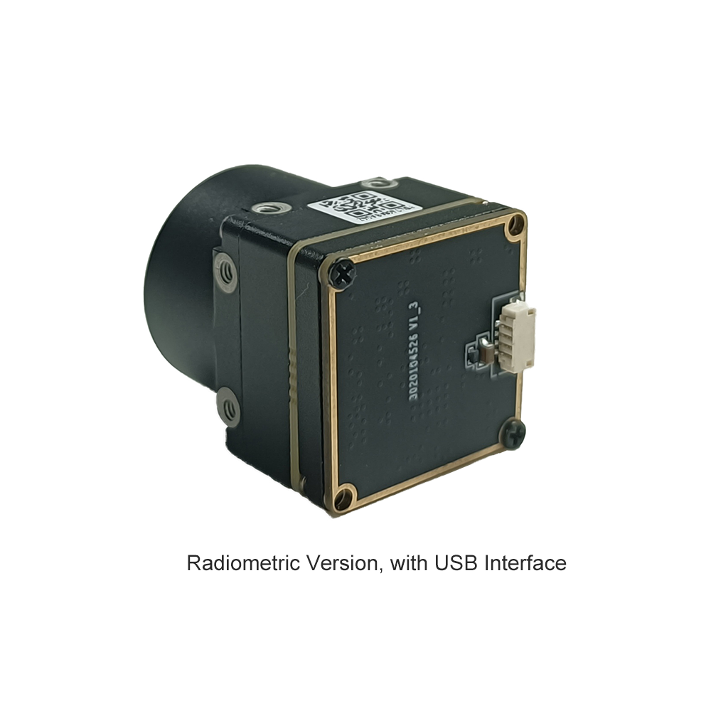
To bring a CVBS thermal feed into an edge compute board, integrators use hardware video capture chips (such as the Analog Devices ADV7180 or ADV7280 series) wired directly to the processor's parallel camera interface or MIPI-CSI2 port. These chips digitize the composite analog waveform into standard digital YUV/RGB frames with less than one frame period of processing latency. Alternatively, low-latency industrial USB UVC capture dongles can convert the composite video directly into a standard V4L2 (Video4Linux2) video stream on the host OS. This setup allows systems to utilize the ultra-low latency and long-distance cabling advantages of CVBS for primary transmission, while still digitizing the feed locally for edge computing, automatic target detection, and dynamic tracking.
📚 Piśmiennictwo i dalsze lektury
- Standard branżowy: Fundamental physical laws of thermal radiation, spectral bands, and microbolometer radiometry: Wikipedia Thermal Imaging Science Guide
- Component Sourcing: Industrial manufacturing and OEM wholesale procurement channel: KUYANG Electronic Storefront
- Related Engineering Guide: Strategic architecture for long-range drone electro-optical payload integration: Best Long-Range Thermal Camera Modules for Drone & AI OEM Integration
- Katalog produktów: Comprehensive technical specifications across bare-board and enclosed thermal imaging sensors: Uncooled LWIR Long-Wave Infrared Thermal Imaging Cameras
- Embedded Linux Architecture: Low-level hardware configuration, kernel modules, and device trees for embedded cores: RS300 V4L2 Driver Setup Guide for Embedded Thermal Imaging Modules