Thermal Video Camera Cheap: Best Budget Cores & Video Modules Guide
26 октября 2026 г.
Best Thermal Image Camera Guide: From DIY Projects to High-Res OEM Modules
Thermal imaging technology has crossed the threshold from an inaccessible military-grade luxury to a mission-critical sensor tier across industrial automation, aerospace payload design, preventative maintenance, and custom embedded systems. However, the commercial market remains flooded with low-tier consumer novelties, poorly calibrated handheld tools, and obfuscated OEM data sheets that mask sub-par resolution under software interpolation. For system integrators, drone engineers, and industrial reliability managers, choosing the right thermal image camera is not merely an optical upgrade—it directly determines your system’s thermal sensitivity, spatial resolution, telemetry frame rates, and embedded edge computing capabilities.
Selecting an uncooled long-wave infrared (LWIR) solution requires looking past deceptive marketing metrics. A toy-grade sensor outputting interpolated 80×60 thermal frames with a noise-equivalent temperature difference (NETD) exceeding 60mK will completely miss early bearing delamination, failing electrical switchgear, or subtle geothermal variances in agricultural drone mapping. Real-world diagnostic precision demands native vanadium oxide (VOx) focal plane arrays, hardened germanium (Ge) or chalcogenide optics, and low-latency digital video streaming interfaces such as MIPI-CSI2, USB-C, or CVBS analog. This comprehensive technical guide breaks down the core physics of non-contact infrared thermometry, establishes rigorous hardware benchmarking criteria, evaluates high-performance embedded modules, and blueprints custom drone and robotics payload deployments.
Содержание
- 👉 1. Physics & Core Mechanics: How LWIR Microbolometers Capture Thermal Signatures
- 👉 2. Consumer Gimmicks vs. Industrial Radiometry: Spatial Resolution & NETD Metrics
- 👉 3. Technical Benchmarking: High-Performance OEM Core Specifications
- 👉 4. Optics Engineering: Germanium, Chalcogenide Lenses, and IFOV Math
- 👉 5. Systems Integration: Interfacing MIPI, CVBS, and USB-C with Edge AI Compute
- 👉 6. Blueprint: Deploying Uncooled Modules for Drones and Autonomous Robotics
- 👉 7. High-Precision Technical FAQ & Engineering Insights
- 👉 8. Final Architecture Summary & Verification Checklist
1. Physics & Core Mechanics: How LWIR Microbolometers Capture Thermal Signatures
Every piece of matter possessing a thermodynamic temperature above absolute zero (0 Kelvin / −273.15°C) continuously emits electromagnetic energy generated by the stochastic thermal motion of its constituent charged particles. Max Planck quantified this phenomenon through Planck's Radiation Law, which defines the spectral radiance of electromagnetic radiation emitted by a blackbody in thermodynamic equilibrium. In standard industrial, terrestrial, and airborne operating envelopes (−40°C to +500°C), the peak spectral exitance shifts squarely into the Long-Wave Infrared (LWIR) atmospheric transmission window, spanning between 8μm and 14μm, in strict agreement with Wien's Displacement Law.
Unlike visible-spectrum Complementary Metal-Oxide-Semiconductor (CMOS) or Charge-Coupled Device (CCD) image sensors that register reflected visible photons between 0.4μm and 0.7μm, an uncooled thermal image camera relies on an array of micro-machined thermal resistive elements suspended above silicon substrates, termed a microbolometer Focal Plane Array (FPA). To dive deeper into the theoretical underpinnings of radiant flux, surface emissivity, and the Stefan-Boltzmann law ($W = \epsilon \sigma T^4$), engineers frequently consult foundational documentation on Тепловизионная съёмка — Википедия.
At the microstructural level, modern high-performance uncooled detectors utilize thin-film resistor bridges fabricated from Vanadium Oxide (VOx) or Amorphous Silicon (α-Si). Vanadium Oxide stands as the undisputed industrial benchmark owing to its exceptionally high negative Temperature Coefficient of Resistance (TCR), typically ranging from −2% to −3% per Kelvin, combined with significantly lower $1/f$ low-frequency electronic flicker noise compared to amorphous silicon alternatives. Each microbolometer pixel consists of an ultra-thin absorbing membrane supported above a Readout Integrated Circuit (ROIC) by microscopic silicon nitride anchor legs under permanent high-vacuum wafer-level packaging (WLP). The vacuum cavity eliminates convective and conductive heat transfer between the membrane and ambient atmosphere, leaving radiative absorption as the primary thermal exchange mechanism.
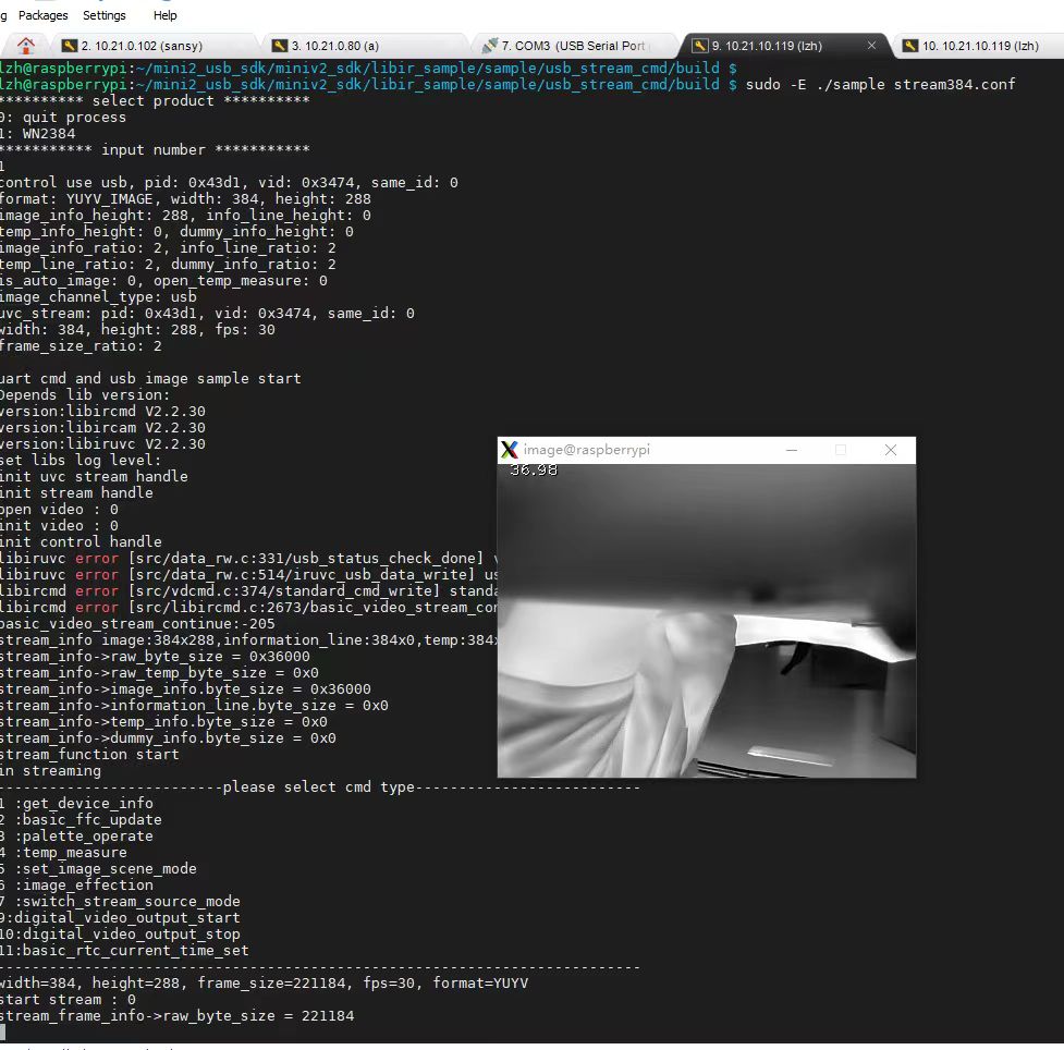
The operational signal conversion chain follows a strict, highly sensitive path:
- ⚙️ Target Emissive Radiance: Infrared energy radiated by the object passes unhindered through the 8μm to 14μm atmospheric transmission window.
- ⚙️ Anti-Reflective Optical Focusing: The incoming waveband passes through an antireflective-coated germanium or chalcogenide lens assembly, blocking short-wave and visible noise while focusing infrared photons directly onto the focal plane array.
- ⚙️ Thermal Membrane Absorption: The incident thermal flux strikes the suspended VOx micro-absorber, causing its micro-bridge temperature to rise or fall in fractions of a millikelvin.
- ⚙️ Electrical Resistance Modulation: The thermal fluctuation alters the material's internal electrical resistance proportional to its negative TCR.
- ⚙️ ROIC Analog Sampling: The underlying CMOS ROIC matrix periodically injects micro-ampere bias currents across each pixel, sampling the resulting micro-voltage shifts line-by-line at typical integration rates between 25Hz and 60Hz.
- ⚙️ High-Resolution Digitization: The analog micro-volt outputs pass directly to onboard low-noise 14-bit or 16-bit Analog-to-Digital Converters (ADCs), outputting raw digital counts representing radiant intensity.
- ⚙️ Digital Signal Processing & NUC: An onboard Digital Signal Processor (DSP) cleans raw counts by running Bad Pixel Replacement (BPR), applying polynomial radiometric temperature lookup algorithms, and periodically deploying a mechanical flag or shutterless algorithm to eliminate thermal drift and fixed-pattern noise (FPN).
- ⚙️ Telemetry Delivery: The system streams fully radiometrically calibrated 14-bit temperature datasets alongside tone-mapped 8-bit visual palettes across high-speed digital buses such as MIPI-CSI2, USB-C, or legacy CVBS composite video lines.
Because microbolometers continuously absorb thermal energy from their surrounding structural housings and digital processing circuits, they are susceptible to internal spatial noise drift. Uncooled cores counteract this via periodic Non-Uniformity Correction (NUC). In mechanical systems, an internal solenoid drops an isothermal shutter blade across the sensor for several frames, providing a uniform temperature field that allows the DSP to zero out spatial pixel offsets. Advanced airborne and long-range surveillance installations running shutter-free architectures consult detailed technical deployment documents such as the LWIR 640-1280 OEM Module Technical Guide to manage extended thermal stabilization without interrupting live targeting or navigation feeds.
2. Consumer Gimmicks vs. Industrial Radiometry: Spatial Resolution & NETD Metrics
The consumer electronics market is heavily saturated with low-cost smartphone dongles and handheld thermal gadgets priced between $150 and $400. While marketing brochures promise revolutionary diagnostic performance, these devices almost universally rely on low-resolution microbolometers—typically measuring 80×60 (4,800 pixels), 120×90 (10,800 pixels), or 160×120 (19,200 pixels). To disguise this massive deficit in spatial detail, manufacturers utilize visual edge-blending algorithms that overlay edge contours captured by an inexpensive visible-light CMOS sensor onto an interpolated thermal background. In unlit electrical cabinets, smoke-choked environments, or zero-lux nocturnal flight paths, the visual camera produces pure black noise, leaving the operator with an unreadable, heavily pixelated thermal blur that fails diagnostic requirements.
True industrial engineering assessments evaluate a thermal image camera across three uncompromising performance metrics:
1. Native Focal Plane Array Pixel Density
Thermal resolution determines spatial diagnostic fidelity. A native 640×512 microbolometer array records 327,680 discrete, independent temperature measurement points every single frame. This represents more than 68 times the actual thermal data captured by an entry-level 80×60 consumer sensor. A 384×288 array yields 110,592 true radiometric pixels—more than double the data of a 256×192 sensor and over 23 times that of an 80×60 toy. This spatial density is the sole factor separating an engineer's ability to clearly differentiate between an overheating trace on an embedded motherboard and a benign nearby capacitor, or resolving failing insulators on a 110kV transmission line from an airborne drone standoff distance of 40 meters.
Разность температур, эквивалентная шуму (NETD)
Quantified strictly in milliKelvin (mK), NETD is the primary metric defining thermal sensitivity. It represents the temperature differential at which the raw electrical signal generated by the sensor is exactly equal to the inherent noise floor of the system ($SNR = 1$). A consumer-grade thermal sensor with an NETD rating of 70mK requires a thermal variation of at least 0.07°C simply to rise above background noise. Conversely, an industrial-grade uncooled VOx sensor achieving an NETD of $\le 35\text{mK}$ or $\le 40\text{mK}$ (measured at $f/1.0$ at 300K) resolves micro-temperature gradients as subtle as 0.035°C. This heightened sensitivity is essential for detecting sub-surface moisture delamination inside aeronautical composite honeycombs, minor gas pipe thermal signatures, or early-stage mechanical bearing friction long before catastrophic structural failure occurs.
3. Calibrated Pixel-by-Pixel Absolute Radiometry
Consumer devices typically output pre-rendered, 8-bit JPEG or MP4 video streams where thermal counts have been irreversibly mapped to arbitrary RGB or Ironbow color palettes. Industrial radiometry requires streaming uncompressed 14-bit or 16-bit digital arrays directly from the ROIC. In a truly radiometric stream, every pixel $(x, y)$ carries a digital count directly convertible into an absolute engineering temperature value (Kelvin, Celsius, or Fahrenheit) via factory calibration polynomial coefficients. This enables real-time downstream processing where software algorithms programmatically adjust for target surface emissivity ($\epsilon$), ambient reflected temperature, relative humidity, and optical atmospheric transmission distance. Engineers evaluating form-factor constraints and onboard radiometric processors should review the handheld and portable thermal camera selection framework for comprehensive comparative analyses.
3. Technical Benchmarking: High-Performance OEM Core Specifications
When selecting embedded thermal cores for custom drone gimbals, autonomous mobile robots (AMRs), predictive maintenance installations, or automated quality assurance lines, engineers must match sensor capabilities with operational realities. Below, we synthesize real-world performance specifications for two flagship OEM modules developed for harsh embedded industrial environments.
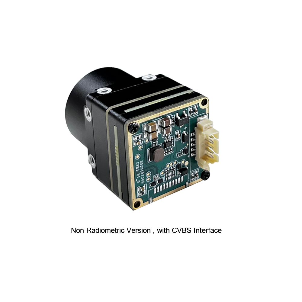
Неохлаждаемый мини 384*288 тепловизионный модуль камеры для дронов
The MINI series infrared thermal imaging temperature measurement module is engineered as a high-precision, ultra-compact, and universal online temperature measurement infrared thermal imager. It utilizes high-grade uncooled Vanadium Oxide detectors delivering sharp native 384×288 resolution, exceptionally stable operational performance, and advanced diagnostic features. Outfitted with multiple hardware output interfaces, this module has become a primary choice for high-demand integration sectors including machine vision, robotic safety inspection, intelligent factory automation, preventative equipment maintenance, and drone airborne surveillance systems.
- ✅ Разрешение: 384×288 pixels native microbolometer array
- ✅ Форм-фактор: Ultra-miniaturized lightweight chassis engineered for sUAS gimbals
- ✅ Video Interfaces: Real-time CVBS composite analog alongside industrial board-to-board digital routing
- ✅ Thermal Measurement: High-precision online surface radiometry covering point, line, and bounding-box area calculations

Неохлаждаемый инфракрасный MIPI 640 384 256 9мм тепловизионный модуль камеры для дронов
The Mini2 640×512 9mm thermal module is an advanced uncooled infrared engine built for ultra-high-definition airborne and robotic perception. Characterized by exceptionally crisp image presentation, an ultra-compact footprint, and competitive OEM economics, this core integrates a native high-density focal plane array supporting direct MIPI-CSI2 data streaming. With support for scalable modes (including 640, 384, and 256 processing regimes), it provides engineers with complete algorithmic control when deploying deep neural networks directly on edge microprocessors.
- ✅ Варианты разрешения: Native 640×512 matrix with multi-resolution scaling modes
- ✅ Оптика: High-transmission integrated 9mm $f/1.0$ Germanium thermal lens
- ✅ Интерфейс: Direct MIPI-CSI2 bus for zero-latency direct memory access to SoC image signal processors
- ✅ Thermal Imaging Performance: Exceptionally low NETD noise ceiling yielding sharp, high-contrast imagery in zero-lux atmospheres
The comparative matrix below outlines core hardware parameters for embedded design evaluations:
| Инженерная метрика | Неохлаждаемый мини-модуль 384*288 | Mini2 640x512 9mm Infrared Module |
|---|---|---|
| Материал детектора | Неохлаждаемый оксид ванадия (VOx) | Неохлаждаемый оксид ванадия (VOx) |
| Собственное разрешение матрицы | 384 × 288 пикселей | 640 × 512 Pixels (Supports 384 & 256 modes) |
| Pixel Pitch Architecture | 12μm / 17μm High-Sensitivity Node | Ultra-Dense 12μm Pitch |
| Чувствительность (NETD) | ≤ 40mK @ $f/1.0, 300\text{K}$ | ≤ 35mK to ≤ 40mK @ $f/1.0$ |
| Operational Frame Rates | 25Hz / 50Hz Fluid Output | 25Hz / 30Hz / 50Hz / 60Hz Low-Latency |
| Primary Optical Assembly | Modular Multi-Interface Mount | Athermalized 9mm Germanium ($f/1.0$) |
| Hardware Bus Interfaces | CVBS Composite Analog / Digital Board-to-Board | MIPI-CSI2 Direct / CVBS / Digital USB-C |
| Radiometric Telemetry | Real-time continuous point, line, and area stats | Pixel-level 14-bit raw radiometric data stream |
For custom sensor housing designs and structural dimension parameters, reference the 384x288 radiometric sensor module deployment manual to verify pinout configurations and voltage thresholds.
4. Optics Engineering: Germanium, Chalcogenide Lenses, and IFOV Math
Conventional optical glasses such as borosilicate (BK7) and fused silica, which form the bedrock of visible-light camera lenses, exhibit near-total opacity within the Long-Wave Infrared spectrum (8μm to 14μm). Directing an 8μm infrared beam at standard glass results in immediate absorption and reflection, rendering it useless for thermal systems. Consequently, an industrial thermal image camera relies on specialized infrared-transmissive crystalline elements:
- ⚙️ Монокристаллический германий (Ge): Germanium remains the benchmark in thermal optics due to its high refractive index (approximately 4.003 at 10.6μm), enabling optical designers to craft lenses with high optical power and minimal spherical aberrations. However, bare germanium surfaces reflect up to 36% of incident radiance per air-to-glass interface. As a result, premium thermal lenses undergo broad-band anti-reflective (BBAR) treatments, often paired with an external Diamond-Like Carbon (DLC) hard coating to withstand airborne dust, salt spray, and physical scratching.
- ⚙️ Халькогенидное стекло: Synthesized from vitrified chemical mixtures of chalcogen elements (sulfur, selenium, tellurium), chalcogenide materials feature a lower thermal coefficient of refractive index ($dn/dT$) than monocrystalline germanium. This enables cost-effective, athermalized lens designs that maintain sharp focus across ambient operating shifts from −40°C to +80°C without complex mechanical focusing linkages.
When selecting optics, engineers must balance field-of-view width against target spatial resolution. This is calculated using the Мгновенным полем зрения (IFOV), which defines the physical angle subtended by a single pixel element on the detector array:
$\text{IFOV (mrad)} = \frac{\text{Pixel Pitch } (p \text{ in }\mu\text{m})}{\text{Focal Length } (f \text{ in mm})}$
Consider the Mini2 640x512 module featuring an ultra-dense $12\mu\text{m}$ pixel pitch paired with its integrated $9\text{mm}$ lens:
$\text{IFOV} = \frac{12\,\mu\text{m}}{9\,\text{mm}} = 1.333\,\text{mrad}$
To determine the physical ground sampling footprint covered by a single pixel at a typical airborne inspection standoff distance of 50 meters, multiply the distance by the IFOV:
$\text{Pixel Footprint} = 50\,\text{m} \times 0.001333\,\text{rad} = 0.0667\,\text{m} = 66.7\,\text{mm}$
Crucially, detecting an anomaly is fundamentally different from accurately measuring its temperature. The Spot Size Ratio (SSR) dictates that to overcome optical point-spread function blur and optical modulation transfer function (MTF) degradation, an object must cover a minimum surface area of at least $3 \times 3$ contiguous physical pixels on the microbolometer FPA to achieve stable radiometric accuracy:
$\text{Minimum Resolvable Radiometric Target Dimension} = 3 \times \text{Pixel Footprint} = 3 \times 66.7\,\text{mm} = 200.1\,\text{mm}$
Consequently, at 50 meters, a 640×512 core with a 9mm lens reliably measures targets that are at least 20cm across. Attempting the same inspection with a lower-resolution module featuring a 17μm pixel pitch pushes the individual pixel footprint to $94.4\text{mm}$, requiring target dimensions to exceed $283\text{mm}$ for accurate measurement. Selecting an inappropriate lens or pixel pitch directly compromises temperature measurement integrity.
5. Systems Integration: Interfacing MIPI, CVBS, and USB-C with Edge AI Compute
Modern embedded thermal vision requires seamless integration with processing hardware such as NVIDIA Jetson Orin Nano, Raspberry Pi Compute Module 4, or industrial x86/ARM systems. System architects generally evaluate three hardware data transport pipelines:
1. The MIPI-CSI2 Ultra-Low Latency Direct Pipeline
For autonomous mobile robotics, real-time object tracking, and deep-learning edge inference, MIPI-CSI2 is the gold standard. By connecting the thermal camera directly to the SoC's hardware image signal processor (ISP), MIPI eliminates the USB stack and OS kernel driver overhead. Data arrives via Direct Memory Access (DMA) into system memory with minimal latency (often under 5 milliseconds).
However, running high-speed MIPI differential data lanes over long physical distances poses signal degradation risks. In dynamic multi-rotor gimbals, mechanical rotation can quickly wear out standard flexible printed circuits (FPCs). To resolve this, aerospace engineers deploy custom, impedance-controlled Человек с микрокоаксиальным кабелем harness assemblies. These micro-coaxial cable bundles deliver crucial RF shielding against high-power brushless motor electromagnetic interference (EMI) and 5.8GHz video transmitters while fitting neatly through compact slip-ring assemblies.
2. The CVBS Analog Pipeline
Modules like the Uncooled Mini 384*288 feature standard baseband CVBS composite analog outputs (NTSC/PAL). In analog FPV drone platforms or legacy industrial control monitors, CVBS requires no operating system initialization, video decoding libraries, or complex communication stacks. It provides an immediate, zero-latency visual stream the millisecond power is applied to the rail.
3. Digital USB-C UVC & Radiometric Metadata Pipeline
Modern thermal modules with native USB interfaces emulate USB Video Class (UVC) devices, allowing them to interface directly with OpenCV, GStreamer, and standard Linux V4L2 frameworks without proprietary kernel patches. Advanced cores split the stream across a virtual dual-port endpoint: one streaming 8-bit visual false-color frames, and the other streaming raw 14-bit ADC counts across a virtual serial port. Below is a production-grade algorithmic pattern for processing these 14-bit digital counts into calibrated Celsius arrays on an embedded edge device:
# Industrial Radiometric Telemetry Parser
импорт cv2
импорт numpy как np

def parse_radiometric_frame(raw_14bit_array, planck_r, planck_b, planck_f, planck_o):
    """
    Vectorized transformation of raw 14-bit digital ADC levels to Celsius arrays.
    Calculated via modified Planck radiation equations embedded in sensor calibration.
    """
    # Strip telemetry control parity bits via bitmasking
    clean_counts = np.bitwise_and(raw_14bit_array, 0x3FFF).astype(np.float32)

    # Apply sensor-specific calibration curve: T_k = B / ln(R / (Counts - O) + F)
    denominator = (planck_r / (clean_counts - planck_o)) + planck_f
    temp_kelvin = planck_b / np.log(np.maximum(denominator, 1.0001))
    temp_celsius = temp_kelvin - 273.15

    # Linear AGC tone-mapping to 8-bit frame for display
    norm_display = cv2.normalize(temp_celsius, None, 0, 255, cv2.NORM_MINMAX, dtype=cv2.CV_8U)
    rendered_colormap = cv2.applyColorMap(norm_display, cv2.COLORMAP_INFERNO)

    return temp_celsius, rendered_colormap
6. Blueprint: Deploying Uncooled Modules for Drones and Autonomous Robotics
Deploying a thermal image camera onto small Unmanned Aerial Systems (sUAS) or Autonomous Mobile Robots (AMRs) presents strict Size, Weight, Power, and Cooling (SWaP-C) constraints. Overlooking these electro-mechanical factors can result in noisy frames, calibration drift, and shortened mission profiles.
1. Power Filtration and Ground Loop Isolation
Microbolometer ROIC circuitry operates at ultra-low microvolt levels. Powering a thermal core from an unfurnished main distribution rail shared with electronic speed controllers (ESCs) and high-current brushless motors introduces intense switching ripple. This ripple manifests across the video frame as rolling horizontal bars, periodic banding, and false temperature spikes.
To ensure a clean, stable signal, power the thermal core through an isolated, multi-stage buck-boost regulator followed by a Low-Dropout (LDO) linear regulator. Target power rail voltage ripple below $15\text{mV}$ peak-to-peak under peak motor thrust. In addition, route analog video signals (CVBS) through dedicated shielded twisted-pair wiring to prevent high-frequency digital ground loops from corrupting video references.
2. Harmonic Mechanical Isolation
High-frequency vibrations generated by drone propellers and electric motor bearings introduce micro-motion jitter that blurs thermal images. Unlike visible CMOS sensors that support fast electronic rolling shutters with exposure times under 1/2000th of a second, an uncooled microbolometer's thermal response time is fundamentally governed by the thermal mass of its suspended VOx membranes—typically between 8ms and 14ms.
Because microbolometers cannot execute instantaneous exposures, high-frequency physical jitter degrades the thermal contrast of adjacent pixels. Payload mounts should feature active 3-axis brushless gimbals coupled with fluorosilicone mechanical dampening balls. These dampers should be tuned to cancel out the frame's specific motor harmonics, which generally range between 120Hz and 220Hz depending on blade pitch and prop diameter.
3. Thermal Equilibrium and Convective Dissipation
Although termed "uncooled," microbolometer cores still generate heat from internal field-programmable gate arrays (FPGAs), ADCs, and digital signal processors. If an OEM module is sealed inside a tight, unventilated 3D-printed enclosure, internal temperatures will steadily climb. This thermal build-up radiates onto the back of the FPA, causing the core's baseline offset to drift and triggering frequent, disruptive recalibration shutter cycles (NUC freezes).
Thermal payload enclosures should be machined from lightweight 6061-T6 aircraft aluminum. This allows the enclosure to function as a structural heat sink that dissipates heat into the surrounding air wash generated by the aircraft's propulsion system.

7. High-Precision Technical FAQ & Engineering Insights
Are sub-$400 consumer thermal cameras actually worth owning, or are they just gimmicky toys?
Can an Android or iOS thermal camera app work without dedicated hardware?
Why should I choose an OEM thermal module instead of a finished handheld unit for robotics or drone builds?
8. Final Architecture Summary & Verification Checklist
Before moving a thermal vision system into production, run through this hardware and software validation checklist:
- ✅ Focal Plane Array Chemistry: Selected Vanadium Oxide (VOx) over Amorphous Silicon (α-Si) for superior thermal sensitivity and lower low-frequency $1/f$ electronic noise.
- ✅ Native Spatial Resolution: Matched resolution to operational standoff distance, ensuring the target covers at least a $3 \times 3$ pixel footprint (384×288 for mid-range systems; 640×512 for high-altitude aerial platforms).
- ✅ Transmissive Optics Validation: Selected an athermalized, anti-reflective DLC-coated monocrystalline Germanium or Chalcogenide lens matching the 8μm to 14μm LWIR band.
- ✅ Data Pipeline Architecture: Implemented direct MIPI-CSI2 connectivity for low-latency AI processing, or isolated CVBS for simple, zero-latency analog video links.
- ✅ Interconnect Shielding: Used micro-coaxial cable assemblies for routing high-speed digital buses through gimbal slip rings and noisy motor environments.
- ✅ Power Supply Cleanliness: Isolated the core's power input using an independent buck-boost converter followed by an LDO regulator, keeping ripple below $15\text{mV}$.
- ✅ Radiometric Parsing Pipeline: Built a processing pipeline capable of converting raw 14-bit digital ADC levels into calibrated Celsius arrays while compensating for target emissivity and atmospheric absorption.
📚 Ссылки и дополнительная литература
- Отраслевой стандарт: Тепловизионная съёмка — Википедия
- Component Technology: Человек с микрокоаксиальным кабелем
- Related Guide (High-Resolution OEM Cores): Najlepszy Dostawca Niechłodzonych Rdzeni Kamer Termowizyjnych LWIR 640-1280 Moduły OEM
- Related Guide (Portable Systems): Руководство по портативным тепловизорам
- Related Guide (384x288 Integration): 384x288 модуль тепловизионной камеры датчик