Руководство по модулю тепловизионной камеры MIPI: высокоточная интеграция периферийного ИИ для Raspberry Pi и дронов
20 июля 2026 г.
Модуль тепловизионной камеры с CMOS-сенсором: руководство по интеграции и OEM-решения
21 июля 2026 г.
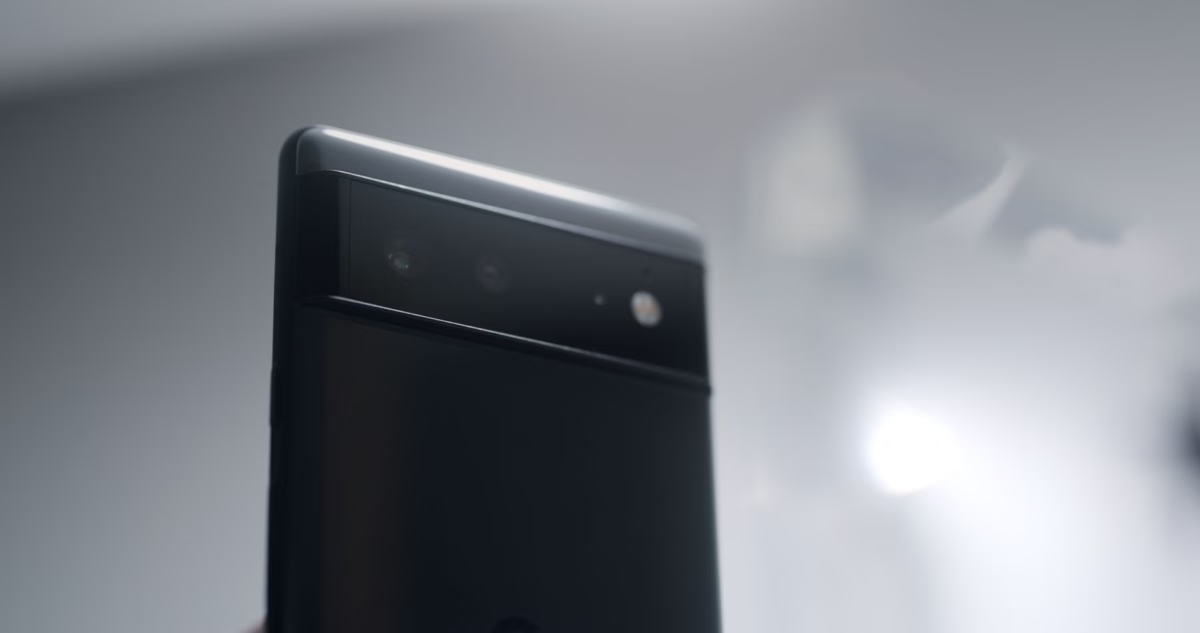
Лучшие модули тепловизионных камер UVC для Linux, Pi и встраиваемых систем
Если вы работаете на передовой разработки оборудования — будь вы системный интегратор, разработчик дронов, оснащающий автономные полезные нагрузки, или инженер по промышленной автоматизации — вы уже знаете расклад. Реальное узкое место при развертывании длинноволнового инфракрасного (LWIR) зондирования — это уже не физическое разрешение сенсора. Настоящая головная боль — то, что я называю "налогом на SDK". Традиционные модули тепловизионных ядер печально известны тем, что требуют закрытых драйверов ядра, бинарных файлов, привязанных к платформе, и запутанных проприетарных программных конвейеров. Попробуйте заставить их работать с кастомным дистрибутивом Linux, современной средой Robot Operating System (ROS 1 или ROS 2) или энергоэффективным Raspberry Pi, и вы быстро окажетесь в интеграционном аду. Это сжигает инженерные часы, задерживает выход на рынок и создает огромные уязвимости для вашей системы граничных вычислений.
Вот в чем дело: стандартные модули тепловизионных камер USB Video Class (UVC) полностью меняют правила игры. Сопоставляя неохлаждаемые микроболометрические сенсоры LWIR напрямую с нативным видеопротоколом USB, эти модули предоставляют тепловизионные потоки напрямую встроенным драйверам вашей операционной системы. Речь идет о Video4Linux2 (V4L2) на Linux и стандартных API DirectShow/MediaFoundation на Windows. Это чистый plug-and-play. Вы можете получать сырые радиометрические или YUV потоки данных прямо из коробки, сводя накладные расходы на интеграцию ПО почти к нулю, освобождая критически важные циклы бортового процессора и делая развертывание Edge AI по-настоящему практичным. Это руководство — полный, проверенный в бою проектный план по выбору, настройке и программированию высокопроизводительных неохлаждаемых тепловизионных камер UVC и raw digital в экосистемах встраиваемого Linux.
Содержание
- 👉 Что такое нативный модуль тепловизионной камеры UVC?
- 👉 UVC USB-C против MIPI CSI-2 против сетевых решений (потоки RJ45 IP)
- 👉 Архитектура драйвера V4L2, интеграция с ROS и конфигурации Raspberry Pi
- 👉 Декодирование потока: отделение визуальной шкалы серого от сырых радиометрических матриц
- 👉 Оптическая динамика микроболометров: шаг пикселя (12 мкм против 17 мкм) и спектральный отклик
- 👉 Промышленные профили продуктов и реальные рабочие параметры
- 👉 Реализации драйверов на C++ и Python для встраиваемых платформ Linux
- 👉 Инженерный FAQ с глубоким погружением
Понимание модулей тепловизионных камер UVC
Расширяя встраиваемые горизонты: что такое модуль тепловизионной камеры UVC?
Если говорить по сути, модуль тепловизионной камеры UVC — это просто неохлаждаемый инфракрасный сенсор в паре с бортовым цифровым бэкендом, который говорит на языке стандартных параметров USB-IF UVC. В отличие от типичных потребительских тепловизионных решений, которые заставляют вас запускать проприетарные программные обертки, ядро UVC работает точно так же, как стандартная веб-камера. Оно подключается к хостовой операционной системе без каких-либо проблем, что делает его надежным, кроссплатформенным выбором для серьезных промышленных проектов.
Давайте заглянем под капот. Весь процесс начинается с оптики. Длинноволновое инфракрасное излучение (обычно находящееся в спектральном диапазоне от 8 мкм до 14 мкм) проходит через специальный кусок германия — стекло здесь не подходит — и фокусируется на матрицу микроболометров. Эти микроболометры обычно изготавливаются из оксида ванадия (VOx) или аморфного кремния (a-Si). Когда инфракрасное излучение попадает на них, они меняют сопротивление в зависимости от своей температуры. Это изменение считывается бортовым аналого-цифровым преобразователем (АЦП) и преобразуется в регистры сырых цифровых значений, обычно с разрядностью 14 или 16 бит.
Затем встроенный ASIC или DSP берет на себя основную вычислительную нагрузку. Он выполняет критически важные коррекции в реальном времени, такие как коррекция неоднородности (NUC), замена дефектных пикселей (BPR) и автоматическая регулировка усиления (AGC). Затем, вместо выгрузки этих обработанных данных по специализированной параллельной шине, ASIC упаковывает их в стандартные UVC-совместимые USB-видеопакеты. Независимо от того, подключаетесь ли вы через USB-C, micro-USB или защищенный межплатный разъем JST, устройство передает поток напрямую в регистры памяти главного процессора, используя стандартные драйверы ОС.
На практике главное преимущество здесь — надежность. Если вы выполните обычное обновление ядра в системе Ubuntu или Debian, это не нарушит работу вашего сенсорного конвейера. Это особенно важно при создании сложного, критически важного оборудования, такого как беспилотные летательные аппараты (БПЛА), где бортовой компьютер работает с патчем реального времени, например PREEMPT_RT. Поскольку встроенный процессор камеры сам выполняет сложные корректирующие вычисления — NUC, замену дефектов и сжатие динамического диапазона, — ваш центральный процессор не перегружается, оставляя свои циклы свободными для компьютерного зрения, планирования маршрута или нейронных сетей.
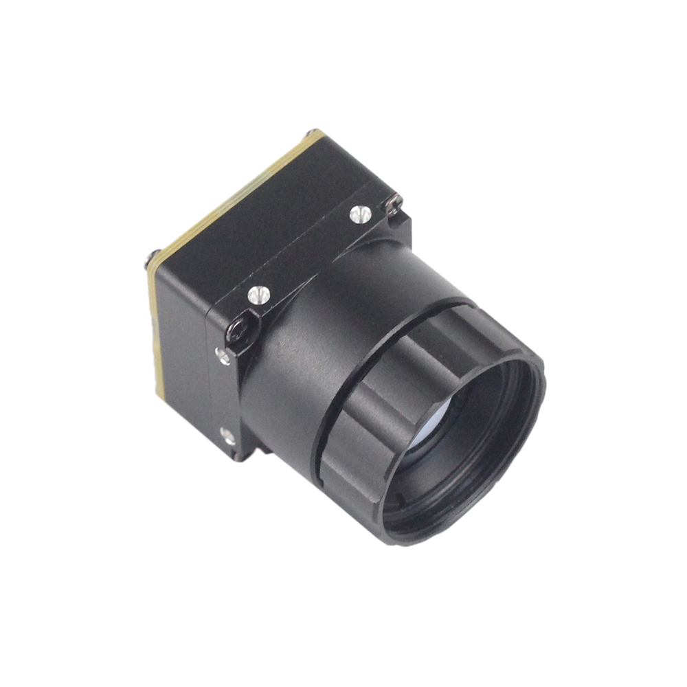
Сравнение аппаратных интерфейсов: UVC USB-C против MIPI CSI-2 против потоковых устройств RJ45 RTSP/IP
Оценка физических соединений
Выбор правильного физического соединения определит границы всего вашего проекта — он зафиксирует максимальную частоту кадров, ограничения по разрешению, задержку в системе и максимальную длину кабелей. Когда вы работаете в CAD-системе над схемой тепловизионного захвата, вы, как правило, рассматриваете три физических варианта: USB, MIPI CSI-2 или потоковую передачу по Ethernet через RJ45.
Интерфейс UVC USB
На практике мы любим стандартные конвейеры USB, потому что они невероятно упрощают нам жизнь. Через физический интерфейс USB 2.0 или 3.0 (обычно это стандартный Type-C или межплатный разъем JST) модуль идентифицирует себя с помощью базовых, предсказуемых дескрипторов USB-видео. Он запрашивает конечные точки массовой или изохронной передачи и выдает чистые, необработанные цифровые потоки YUYV, MJPEG или монохромные. Никакой компиляции пользовательских драйверов ядра, никакой борьбы со странными настройками исходников — все просто работает.
Единственная реальная сложность здесь — это физическая трассировка. Стандартные высокоскоростные дифференциальные пары USB не могут передавать сигнал на большие расстояния без его деградации, и они очень чувствительны к электромагнитным помехам (EMI). Если вы проектируете компоновку массивов внутри мощной рамы дрона с высоковольтными ESC или рядом с мощными промышленными сервоприводами, вам необходимо тщательно экранировать линии USB. Тем не менее, для тесно связанных систем, таких как нашлемные дисплеи, ручные мониторы и компактные периферийные устройства, USB-UVC — это, безусловно, путь наименьшего сопротивления.
Интерфейс MIPI CSI-2
Если вы выжимаете каждую микросекунду из своего конвейера, MIPI CSI-2 — это тяжелая артиллерия. Он передает сырые, несжатые данные микроболометра напрямую в аппаратный процессор сигналов изображения (ISP) вашего центрального процессора. Речь идет об абсолютно минимальной задержке, когда кадры попадают прямо в буферы памяти через DMA. Это стандартный выбор для профессиональных стабилизированных подвесов дронов, где контуры управления полетом зависят от оптического потока или визуального отслеживания.
Но будьте предупреждены: стоимость разработки высока. MIPI CSI-2 — это не «подключи и работай». У него нет самоописывающих дескрипторов. Вам придется разрабатывать собственные пакеты поддержки платформы (BSP) и наложения дерева устройств, а также трассировать высокоскоростные дифференциальные линии с жесткими ограничениями по согласованию длины дорожек и целевым импедансом на вашей печатной плате. Если вы создаете прототип или строите системы малого и среднего объема, MIPI может превратиться в серьезное инженерное узкое место.
Сетевое подключение RJ45 (модули RTSP/IP)
Когда вам нужно передать видеопоток по всему объекту, вам нужна сетевая установка. Эти модули интегрируют дополнительную ASIC для сжатия видео на самой плате, упаковывая тепловые кадры в стандартные потоки H.264 или H.265, передаваемые по протоколам RTSP, RTMP или ONVIF. Вы можете прокладывать кабели Ethernet Cat6 на расстояние до 100 метров без единого повторителя — идеально для организации периметральной безопасности, мониторов подстанций или систем структурного мониторинга.
Отличные сетевые решения «система-на-кристалле», адаптированные для этих сред, широко разрабатываются специализированными поставщиками оборудования, такими как JM Чип. Однако имейте в виду, что кодирование кадров на сенсоре добавляет задержку сжатия, а декодирование потока на другом конце сжигает циклы процессора на вашей целевой машине, что делает его менее подходящим для высокоскоростного динамического отслеживания или сырых контуров управления с низкой задержкой.
Linux Kernel & V4L2: Pure Plug-and-Play Driver Architecture for Raspberry Pi and ROS
On modern ARMv7 and ARMv8 embedded Linux boards—such as the Broadcom BCM2711/BCM2712 powering the Raspberry Pi 4 and 5—the Linux kernel automatically loads the standard uvcvideo module the moment you hook up the device. That camera maps cleanly to /dev/videoX.
Let's map out this software architecture. Under the hood, the raw physical UVC thermal core connects via USB. The kernel's native uvcvideo driver intercepts it, instantly exposing it to V4L2 (Video4Linux2). This populates node devices at /dev/videoX, allowing downstream frameworks—like ROS 1's usb_cam node or ROS 2's v4l2_camera container—to grab streams flawlessly. You end up with standard visual topics (like /thermal/image_raw) ready for down-the-line vision tasks or high-fidelity 16-bit matrices ready for automated scripts.
If you're running Robot Operating System (ROS 1 or ROS 2) architectures, you can bind standard driver nodes directly to the device path and start publishing standard image topics (sensor_msgs/Image). To query or configure device parameters (like frame rates, target resolutions, or gain modes) dynamically without writing code, use the standard command-line tools in the terminal:
# Query system-registered V4L2 USB devices
v4l2-ctl --list-devices

# View pixel stream formats supported by the connected thermal module
v4l2-ctl -d /dev/video0 --list-formats-ext
In multi-sensor robotic setups, this native architecture eliminates structural headaches. You don't have to worry about third-party SDK dependencies clashing with your workspace. You can use V4L2 IOCTL commands directly in your code to alter camera exposure bias, cycle pseudo-color overlays, or switch between high and low gain modes on-the-fly. For rugged drone implementations or outdoor integrations, you can also see trace configurations implemented by operators like OBSETECH who specialize in deploying high-performance payload cameras under tough, uncooperative outdoor conditions.
Decoding the Stream: Visual YUV Frame Buffer vs. Raw Radiometric Temperature Data
While a UVC thermal module streams standard-looking webcam packets (using familiar pixel formats like MJPEG, YUYV, or RGB24), you need to understand that the output data stream can represent two entirely different pipelines depending on your development requirements.
1. Visual Color-Mapped Streams (YUYV/MJPEG)
In this mode, the camera's onboard DSP takes the raw, high-fidelity thermal information and converts it down to an 8-bit visual scale (0 to 255 values, often colorized using standard palettes like Ironbow, Rainbow, or raw Grayscale). This stream is what you want if you are displaying a live image for a human screen, building a mobile monitor, or feeding a visual deep neural network (like running YOLO or proprietary inference models to identify humans or machinery in pitch darkness).
The catch? You lose the actual raw temperature data. Because the onboard processor continuously scales the contrast to make the image clear to human eyes, a pixel value of 150 on the screen does not represent a static, absolute temperature. If you need to map precise temperature trends, visual streams won't cut it.
2. Raw Radiometric Streams (Y16 / 14-Bit Monochromatic)
To pull actual, absolute physical temperatures, you need to configure your V4L2 pipeline to capture uncompressed Y16 raw frames. In this mode, every pixel is delivered as a raw 14-bit or 16-bit Digital Number (DN) mapping directly to the micro-voltage variations of the microbolometer.
By requesting Y16, you turn every pixel on the array into a calibrated, contact-free thermometer. Assuming your core module has been calibrated at the factory, your software applies a linear equation to translate this raw digital map:
To convert this raw sensor data into standard Celsius units, you can apply the following calculation to each pixel in python or C++:
Bottom line? If you are building automated thermal inspection loops, you must read raw Y16 frames. Letting high-level media libraries touch the stream will mangle your data with lossy compression or smoothing filters, corrupting your thermal calibration matrices. For a practical look at how these calibrated matrices can check physical targets—like keeping high-voltage power networks safe—check out our technical guide: How to Detect Transformer Faults Effortlessly: Thermal Imaging Guide.
Optical Microbolometer Dynamics: Pixel Pitch and Spectral Response
When selecting and integrating uncooled microbolometers, two main variables determine spatial recognition limits: the microbolometer array's pixel pitch and the optical focal length of its Germanium lens assembly.
Шаг пикселя (12 мкм против 17 мкм)
Modern micro-cores leverage uncooled Vanadium Oxide (VOx) or Amorphous Silicon (a-Si) sensor matrices. While older designs relied on a larger 17µm pixel pitch, modern cores leverage a tighter 12µm pixel pitch. This reduction in pixel pitch delivers a major engineering advantage: it decreases the physical footprint of the sensor array while maintaining the exact same resolution.
Consequently, a 12µm core can achieve the identical Field of View (FOV) of a 17µm sensor while using a smaller, lighter, and more cost-effective Germanium optical lens. At the same time, the reduced thermal mass of each individual sensor element on a 12µm pitch chip lowers thermal noise, yielding a highly competitive Noise Equivalent Temperature Difference (NETD) of under 40mK or 50mK.
Optomechanical Calculations
Field layouts are determined by calculating the spatial resolution, also known as the Instantaneous Field of View (IFOV). Calculate the theoretical pixel footprint with the following formula:
Где d is the physical pixel pitch and f is the optical focal length of the Germanium lens. To compute the horizontal Field of View (HFOV) for a 640 x 512 array using a 9mm lens package on a 12µm pitch core:
HFOV = 2 * arctan(Array Width / (2 * f)) = 2 * arctan(7.68 / 18) ≈ 46.2°
By utilizing a 12µm architecture combined with a 9mm target focus, system developers can deploy wide-angle thermal vision systems in highly restricted physical envelopes, making it ideal for compact multi-sensor drone gimbals. If manual mobile target-acquisition or long-range reconnaissance is required over raw embedded PCB modules, read-up on physical portable scopes inside our catalog detailing Wholesale Night Reconnaissance Infrared Binoculars.
Industrial Product Profiles & Real Performance Parameters
Engineers designing industrial monitoring systems, agricultural drones, and automated security grids require deeply documented technical specifications. The following comprehensive comparison highlights two cutting-edge uncooled thermal core designs available in our direct manufacturing catalog:
⚙️ **Product 1:** Uncooled Infrared Mini2 640x512/384x288/256x192 9mm MIPI & UVC-Enabled Thermal Imaging Camera Module (designed for weight-constrained aerial systems).
⚙️ **Product 2:** Uncooled Infrared RJ45 CVBS RTSP IP 640x512 ASIC Thermal Sensor Camera Module (built for networked facility monitors and security integration).
Product Deep-Dive 1: Uncooled Infrared Mipi 640/384/256 9mm For Drones

The Mini2 640x512 9mm Drone Thermal Module is built for weight-sensitive setups where every fraction of a gram cuts directly into flight time. This compact core gives you incredible configuration flexibility because it offers a native USB Type-C physical port (fully UVC class compliant) right alongside a raw MIPI CSI-2 interface on the same board assembly.
With processing logic running natively on its onboard ASIC, the Mini2 renders exceptionally crisp, noise-filtered thermal matrices. It's built to isolate small thermal anomalies in search-and-rescue grids or agricultural surveys, cutting through smoke, fog, and pitch-black nights. The standard 9mm Germanium lens provides an optimized Field of View that integrates nicely into dual-sensor stabilized gimbals alongside standard optical visual zoom cameras.
Посмотреть детали продукта и цены ➔
Product Deep-Dive 2: Uncooled RJ45 CVBS RTSP IP 640*512 ASIC Thermal Core

When you're deploying monitoring networks across a physical factory, chemical plant, or long security perimeter, the Uncooled RJ45 RTSP IP 640x512 ASIC Module is the ruggedized, long-range solution. It completely sidesteps the cable length limits of USB by embedding a full network-enabled interface board on top of the imaging sensor.
The onboard ASIC is hardware-optimized to compress and stream uncooled microbolometer values dynamically. It publishes standard H.264 streams directly over local IP networks via standard RTSP protocols. This means you can hook the camera straight into your existing Video Management System (VMS) without needing a dedicated host PC sitting right next to the physical camera. Built around a detailed 12µm uncooled VOx matrix, this module provides the precise spatial resolution and long-term diagnostic accuracy needed for infrastructure monitoring.
Посмотреть детали продукта и цены ➔
Industrial Vision Engineering FAQ
This technical FAQ section addresses the deep integration challenges faced by hardware architects and embedded software developers when deploying uncooled microbolometers.
Can I run a UVC thermal camera module on Linux and Raspberry Pi without proprietary SDKs?
How do I handle thermal temperature data measurement over UVC?
Are there cost-effective, high-resolution UVC thermal modules for embedded projects?
Technical Integration Guide: Programming UVC Devices Natively in C++ and Python
To transition quickly from hardware prototype to production-grade deployment, developers can hook directly into native system video libraries. The following templates show how to interface with uncooled thermal systems to pull frames and extract metadata without relying on external prop-SDK binaries.
1. Python Implementation: Acquiring and Normalizing Raw Y16 Thermal Streams
Before running the python pipeline scripts on your target development board, ensure the system packages are installed:
sudo apt-get install python3-opencv python3-numpy v4l-utilsThis script binds to your uvc-модуль тепловизионной камеры over V4L2 and captures raw 16-bit monochromatic arrays, processing each frame to display live temperature statistics:
#!/usr/bin/env python3
import cv2
import numpy as np
import sys

def main():
    # Attempt to open the first UVC device system index
    # We enforce the CAP_V4L2 backend to bypass high-level media-framework intervention
    v4l2_device_index = 0
    cap = cv2.VideoCapture(v4l2_device_index, cv2.CAP_V4L2)

    if not cap.isOpened():
        print(f"Error: Critical interface failure opening video device node '/dev/video{v4l2_device_index}'.")
        sys.exit(1)

    # Program V4L2 parameters to request raw 16-bit uncompressed Y16/YUYV streams
    # Many thermal sensors output a native 14-bit depth packet wrapped within a Y16 container
    cap.set(cv2.CAP_PROP_CONVERT_RGB, 0)

    # Request our target native layout resolutions matching the hardware sensor specs
    target_width = 640
    target_height = 512
    cap.set(cv2.CAP_PROP_FRAME_WIDTH, target_width)
    cap.set(cv2.CAP_PROP_FRAME_HEIGHT, target_height)

    print(f"UVC Thermal Stream successfully initialized at {target_width}x{target_height}")
    print("Press the 'ESC' key over the focus frame buffer window to safely terminate runtime loops...")

    try:
        while True:
            ret, frame = cap.read()
            if not ret or frame is None:
                print("Warning: Failed to capture frame from the UVC bus stream.")
                continue

            # Treat incoming raw frame buffer directly as 16-bit array mapping
            # This represents the linear response of each physical pixel on the microbolometer
            raw_16bit_frame = frame.view(dtype=np.uint16).reshape((target_height, target_width))

            # Absolute Temperature Formula Example:
            # Let's assume a standard 100x magnification calibration factor (e.g., Temp = raw_val / 100)
            # This formula returns absolute Celsius values with high precision.
            temperature_matrix_c = (raw_16bit_frame / 100.0) - 273.15

            # Calculate simple spatial statistics across our thermal array
            min_temp = np.min(temperature_matrix_c)
            max_temp = np.max(temperature_matrix_c)
            avg_temp = np.mean(temperature_matrix_c)

            # Normalize the 16-bit raw array down to 8-bit grayscale for display
            normalized_8bit = cv2.normalize(raw_16bit_frame, None, 0, 255, cv2.NORM_MINMAX, dtype=cv2.CV_8U)

            # Apply a pseudo-color map to make the thermal distribution highly visible
            colorized_thermal_render = cv2.applyColorMap(normalized_8bit, cv2.COLORMAP_JET)

            # Render key monitoring metrics on the visual display overlay
            overlay_text = f"Temp Scope: Min={min_temp:.1f}C | Max={max_temp:.1f}C | Avg={avg_temp:.1f}C"
            cv2.putText(colorized_thermal_render, overlay_text, (15, 30),
                        cv2.FONT_HERSHEY_SIMPLEX, 0.6, (255, 255, 255), 2, cv2.LINE_AA)

            # Draw thermal visualization to active desktop screen
            cv2.imshow("Industrial Thermal Analytics Portal", colorized_thermal_render)

            # Check for Esc key press (ASC-II Code 27)
            key = cv2.waitKey(1) & 0xFF
            if key == 27:
                break

    finally:
        # Guarantee physical port release and destroy open render windows
        cap.release()
        cv2.destroyAllWindows()
        print("UVC Stream successfully closed. System exited cleanly.")

if __name__ == "__main__":
    main()
2. C++ Implementation: Fast Low-Latency Frame Capture via Linux V4L2 and OpenCV Core
For high-frequency processing loops, tracking fast-moving airborne targets, or building low-overhead embedded pipelines, native C++ provides optimal frame rates and minimal system overhead. To compile the application, use the following command:
g++ -O3 main.cpp -o thermal_capture `pkg-config --cflags --libs opencv4`Below is the low-latency capture pipeline source code:
#include <iostream>
#include <opencv2/opencv.hpp>
#include <opencv2/videoio.hpp>

// Explicitly define physical camera parameters
#define CAMERA_FPS 25
#define TARGET_WIDTH 640
#define TARGET_HEIGHT 512

int main() {
    // Instantiate raw capture driver context bound strictly via standard v4l2 backend
    cv::VideoCapture cap(0, cv::CAP_V4L2);

    if(!cap.isOpened()) {
        std::cerr << "Critical Error: Could not bind to target /dev/video0 interface!" << std::endl;
        return -1;
    }

    // Explicitly request video conversion bypass configuration
    // This allows the raw 16-bit pixel data array to pass untouched to the CPU memory
    cap.set(cv::CAP_PROP_CONVERT_RGB, 0);
    cap.set(cv::CAP_PROP_FRAME_WIDTH, TARGET_WIDTH);
    cap.set(cv::CAP_PROP_FRAME_HEIGHT, TARGET_HEIGHT);

    std::cout << "[SYSTEM ACTIVE] Stream started at resolution configuration: "
              << TARGET_WIDTH << "x" << TARGET_HEIGHT << " @ " << CAMERA_FPS << " FPS" << std::endl;

    cv::Mat rawFrame;
    cv::Mat normalized8Bit;
    cv::Mat colorizedOutput;

    while(true) {
        cap >> rawFrame;
        if(rawFrame.empty()) {
            std::cerr << "[WARNING] Latency dropped a buffer packet! Frame was empty." << std::endl;
            continue;
        }

        // OpenCV interprets raw, un-RGB-converted 16-bit Y16 thermal matrices as CV_16UC1 (1-channel 16-bit)
        // Convert to standard CV_8UC1 (1-channel 8-bit) using robust automatic calibration scaling
        double minVal, maxVal;
        cv::minMaxLoc(rawFrame, &minVal, &maxVal);

        // Normalize raw data dynamically to make the thermal details visible
        double scale = 255.0 / (maxVal - minVal);
        rawFrame.convertTo(normalized8Bit, CV_8UC1, scale, -minVal * scale);

        // Apply a highly dynamic Colormap rendering pipeline
        cv::applyColorMap(normalized8Bit, colorizedOutput, cv::COLORMAP_INFERNO);

        // Render crosshairs at the center pixel location to track spatial temperature trends
        int centerX = TARGET_WIDTH / 2;
        int centerY = TARGET_HEIGHT / 2;

        // Grab the raw value at the crosshair and convert to representative temp
        uint16_t centerRawVal = rawFrame.at<uint16_t>(centerY, centerX);
        double centerTempCelsius = (centerRawVal / 100.0) - 273.15;

        // Print center temperature value directly onto screen buffer rendering
        std::string labelText = "Center Temp: " + std::to_string(centerTempCelsius).substr(0, 5) + " C";
        cv::putText(colorizedOutput, labelText, cv::Point(20, 40),
                    cv::FONT_HERSHEY_COMPLEX_SMALL, 1.0, cv::Scalar(255, 255, 255), 2);

        // Draw crosshair overlay
        cv::line(colorizedOutput, cv::Point(centerX - 10, centerY), cv::Point(centerX + 10, centerY), cv::Scalar(0, 255, 0), 2);
        cv::line(colorizedOutput, cv::Point(centerX, centerY - 10), cv::Point(centerX, centerY + 10), cv::Scalar(0, 255, 0), 2);

        // Draw dynamic view portal on active screen
        cv::imshow("Embedded Linux Thermal Vision Terminal Portal", colorizedOutput);

        // Press 'q' or ESC (ASC-II Code 27) to break the capture loop
        char keyPress = (char)cv::waitKey(1);
        if (keyPress == 'q' || keyPress == 27) {
            break;
        }
    }

    cap.release();
    cv::destroyAllWindows();
    std::cout << "[SYSTEM CLOSE] Hardware channel freed. Terminating program operations." << std::endl;
    return 0;
}
Calibration & Uniformity Maintenance Practices
Flat Field Correction (FFC / Shutter Calibration)
Because uncooled microbolometers are highly sensitive to thermal gradients within the camera chassis itself, image drift can accumulate over extended runtime periods. This thermal drift manifests as spatial pattern noise across the digital frame buffer, which degrades measurement accuracy and visual quality.
To correct this, uncooled camera cores use an automated or manual program cycle called Flat Field Correction (FFC). During an FFC cycle, a mechanical shutter (usually a small, unheated uniform plate) drops in front of the uncooled microbolometer sensor array for a split second. The camera's internal processor reads this perfectly flat thermal target and resets any drifting pixel offsets back to a uniform baseline. This ensures that your temperature readings and image quality remain consistent and accurate over long periods of use.
Custom Software Shutter Triggers
While auto-FFC runs on its own by default, this shutter event freezes the video stream for about 200–500 milliseconds. In high-stakes applications—like tracking targets from a high-speed drone or landing an autonomous vehicle—this sudden freeze can interrupt critical operations.
To solve this, developers can use custom software overrides. By using UVC Extension Units (XUs) to trigger the FFC cycle programmatically over the USB bus, designers can suppress the automatic internal timer. This allows the system to defer calibration until a more convenient time, such as when a drone is hovering safely or when analytical computational loops are temporarily paused. This approach ensures uninterrupted video when performance is critical.
Architectural Design Recommendations
- ✅ To explore our complete engineering catalog of advanced long-range uncooled thermal sensor targets, bare-board cores, and industrial analytics assemblies, bookmark our primary Thermal-Image Blog Hub.
- ✅ For deep-dive custom requests, pin-out schematics, specific lens combinations, or developer SDK support documents, contact our engineering support desk directly at Purpleriver Products Page to bring your embedded machine vision projects to life.
📚 Ссылки и дополнительная литература
- Отраслевой стандарт: OBSETECH Payload Guides | JM Chip System-On-Chip Integration Standards
- Связанное руководство: How to Detect Transformer Faults Effortlessly: Thermal Imaging Guide