UVC Thermal Camera Module: High-Precision OEM Solutions for Linux, Pi & Embedded AI
2026年9月18日
USB Thermal Camera Module 640x512: Compact LWIR Core for Embedded & Drone Vision
System architects and aerospace hardware engineers face an unforgiving trade-off matrix when integrating long-wave infrared (LWIR) vision into unmanned aerial vehicles (UAVs), tactical robotics, and SWaP-constrained (Size, Weight, Power, and Cost) edge-AI platforms. Legacy military-grade thermal cores frequently impose massive physical envelopes, require complex carrier boards with proprietary low-voltage differential signaling (LVDS) or Camera Link protocols, generate severe parasitic thermal loads, and demand multiple non-standard DC voltage rails. Conversely, consumer-grade USB thermal dongles designed for mobile diagnostics introduce unacceptable frame jitter, non-deterministic non-uniformity correction (NUC) shutter freezes, high-latency processing pipelines, and closed proprietary API wrappers that prevent direct integration with native operating system drivers and deterministic autonomy frameworks.
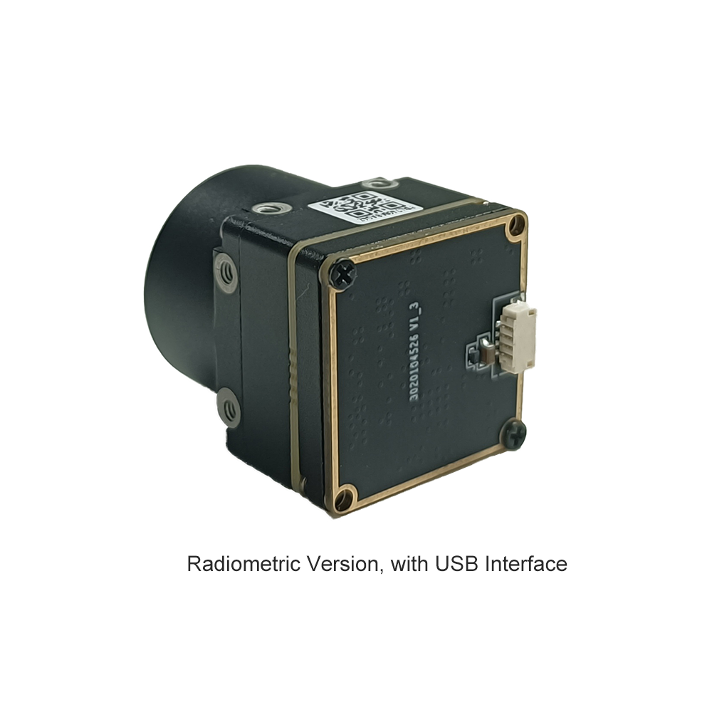
The engineering solution to these architectural bottlenecks lies in the high-density 21mm × 21mm micro-chassis usb thermal camera module 640x512. By coupling an advanced uncooled Vanadium Oxide (VOx) focal plane array (FPA) directly to an industrial-grade USB Video Class (UVC) 1.1/1.5 transport controller, this modular core provides an uncompressed, deterministic 16-bit radiometric pixel pipeline straight into embedded Linux, Robot Operating System (ROS/ROS2), and NVIDIA Jetson computing architectures. Eliminating intermediate deserializer bridge boards and custom frame-grabbers reduces integration timelines from quarters to days. Hardware developers can now harness high-resolution thermal awareness, sub-40mK thermal sensitivity, and calibrated surface temperature extraction within a package that draws minimal power and contributes virtually zero parasitic payload mass to micro-gimbal platforms.
Содержание
- 👉 1. Micro-Bolometer Architecture: 12μm VOx vs. Legacy 17μm a-Si
- 👉 2. Radiometric Signal Pipeline: From Photons to 14-Bit/16-Bit Digital Values
- 👉 3. High-Bandwidth Interfacing: Native UVC, V4L2, and Low-Latency Ingestion
- 👉 4. Optical Architectures: Germanium Elements & DRI Calculations
- 👉 5. Drone Gimbals, Robotics & Edge AI Automation
- 👉 6. Core Hardware Comparison: Industrial USB LWIR Modules
- 👉 7. High-Density Technical FAQ
1. Micro-Bolometer Architecture: 12μm VOx vs. Legacy 17μm a-Si
1.1 Solid-State Physics of Vanadium Oxide (VOx) Detection
At the core of modern LWIR detection is the microbolometer, an array of microscopic suspended thermal absorber bridges fabricated directly onto a silicon Read-Out Integrated Circuit (ROIC) via surface micromachining techniques. When incoming thermal radiation between the 8μm and 14μm atmospheric transmission windows strikes the active absorber material, the micro-bridge heats up, altering its electrical resistance. The performance differential between competing microbolometer technologies boils down fundamentally to the thin-film material deposited on these bridges: Vanadium Oxide (VOx) versus Amorphous Silicon (a-Si).
Vanadium Oxide is a transition metal oxide exhibiting multiple phases that undergoes a significant metal-to-insulator transition. In microbolometer design, mixed-phase VOx films deliver a high Temperature Coefficient of Resistance (TCR), typically operating within the range of -2% to -3% per Kelvin at room temperature. In contrast, standard amorphous silicon arrays rarely exceed a TCR of -1.5% to -2% per Kelvin without introducing unstable structural 1/f flicker noise. Because VOx maintains a crystalline-ordered atomic matrix compared to the disordered covalent network of a-Si, VOx detectors exhibit vastly superior noise performance across low electrical frequencies. This minimization of 1/f noise translates directly into enhanced thermal sensitivity, defined as Noise Equivalent Temperature Difference (NETD). An industrial-grade VOx sensor regularly achieves an NETD under 40mK (and frequently under 30mK with optimized ROIC integration), enabling it to discern micro-Kelvin thermal differentials in challenging, low-thermal-contrast atmospheric conditions such as fog, marine haze, or rain.
Furthermore, VOx materials demonstrate exceptional thermal stability and baseline recovery over extended military and aerospace temperature envelopes ranging from -40°C to +85°C. Amorphous silicon arrays exhibit progressive dielectric degradation and thermal hysteresis under prolonged thermal cycling, requiring frequent, aggressive non-uniformity recalibrations to suppress fixed-pattern noise (FPN). To properly integrate such sensitive sensor arrays without inducing mechanical or thermal stresses on the delicate vacuum-sealed package, engineers should consult the comprehensive przewodnik integracji rdzenia kamery termicznej.
1.2 The 12μm Scaling Advantage in Lens Size and SWaP-C
The transition from legacy 17μm pixel pitch architectures down to contemporary 12μm lithography represents a monumental leap forward for SWaP-C optimization. The physical dimensions of the focal plane array scale linearly with pixel pitch: a 640×512 resolution array fabricated with a 17μm pitch results in an active sensor diagonal of approximately 13.93mm (active area: 10.88mm × 8.70mm). Conversely, the identical 640×512 array implemented on a 12μm node yields a diagonal of merely 9.83mm (active area: 7.68mm × 6.14mm)—a staggering 50.2% reduction in total sensor surface footprint.
From an optical engineering standpoint, reducing the focal plane array dimensions directly impacts the optical elements required to achieve an equivalent field of view (FOV). The focal length \(f\) necessary to produce a specific horizontal field of view (HFOV) is governed by the basic geometric optical relation:
f = \frac{W}{2 \cdot \tan(\text{HFOV}/2)}
Where \(W\) is the physical width of the sensor array. Because a 12μm array is nearly 30% narrower than a 17μm array for the same pixel count, the optical focal length required to deliver the exact same angular field of view is scaled down by approximately 29.4%. For example, an application requiring an 18° HFOV on a 17μm core demands a 35mm focal length objective. On a 12μm core, the exact same 18° HFOV is achieved using an optical lens with a focal length of only ~24.5mm.
Because Germanium (Ge) optics are extremely dense (density of crystalline Germanium is 5.323 g/cm³) and optically expensive, shrinking the focal length—and consequently reducing the clear optical aperture diameter needed to maintain a fast f/1.0 or f/1.1 numerical aperture—dramatically slashes the mass and volume of the optical stack. The mass of a spherical or aspheric Germanium lens scales roughly with the cube of its physical diameter. Consequently, transitioning to a 12μm 640×512 microbolometer enables drone gimbal designers to reduce the optical payload mass by up to 60%, drastically cutting rotational inertia, extending UAV flight endurance, and allowing the deployment of smaller, lower-power brushless direct-drive motors.
2. Radiometric Signal Pipeline: From Photons to 14-Bit/16-Bit Digital Values
2.1 Analog Front-End (AFE) and On-Die ADC Quantization
Converting micro-Kelvin thermal gradients into usable digital data requires an ultra-low-noise analog front-end (AFE) integrated directly onto the silicon ROIC underneath the microbolometer bridge array. Each individual pixel is pulsed with a highly regulated, ultra-stable bias voltage during its corresponding row readout cycle. The minute variation in resistance caused by absorbed infrared photons modulates the current traversing the VOx resistor. This differential current is integrated across a low-noise capacitive transimpedance amplifier (CTIA) located at the column level of the ROIC.
To preserve absolute thermal fidelity and prevent dynamic range compression, modern LWIR cores utilize high-precision on-die analog-to-digital converters (ADCs), quantizing the analog integration voltages into 14-bit or 16-bit digital words. Quantization at this bit depth yields 16,384 to 65,536 distinct discrete digital numbers (DN) per pixel. This ultra-wide dynamic range is vital: it enables the sensor to simultaneously resolve fine 0.04°C temperature differentials across human skin while preserving dynamic headroom to capture high-temperature industrial anomalies exceeding 550°C without saturating the readout columns into clipping.
2.2 Real-Time Non-Uniformity Correction (NUC) and Defective Pixel Replacement (DPR)
Due to atomic-scale lithographic manufacturing variations across the focal plane, no two microbolometer pixels exhibit identical baseline resistance or thermal responsivity. If raw digital signals from the ROIC were visualized directly, the scene would be completely obscured by fixed-pattern noise (FPN), looking like a heavy static veil. To resolve this, the internal digital signal processor (DSP) of the usb thermal camera module 640x512 applies real-time two-point Non-Uniformity Correction (NUC) on every incoming frame.
The standard linear correction model calculates the corrected pixel value \(Y_{i,j}\) from the raw input \(X_{i,j}\) using factory-calibrated gain (\(G_{i,j}\)) and offset (\(O_{i,j}\)) matrices:
Y_{i,j} = G_{i,j} \cdot X_{i,j} + O_{i,j}
While gain coefficients remain relatively static over the operating lifetime of the core, offset values drift continuously as the internal core temperature shifts due to ambient variations and internal component dissipation. High-performance industrial cores manage this using a dual strategy: an integrated miniature mechanical solenoid shutter that periodically closes across the sensor for 200–300 milliseconds to acquire a uniform thermal reference plane, coupled with proprietary, intelligent "shutterless" scene-based non-uniformity correction (SBNUC) algorithms. SBNUC algorithms monitor motion dynamics and statistical spatio-temporal scene flow to equalize drifting offsets dynamically, preventing irritating visual freezes during time-critical drone flight trajectories or high-speed robotic guidance.
Simultaneously, Defective Pixel Replacement (DPR) engines operate at hardware speed inside the FPGA/DSP fabric. Microbolometer manufacturing yield inevitably produces a minute percentage of dead, locked, or excessively noisy "blinking" pixels. The DPR pipeline maps these locations against a non-volatile factory defect table stored within the core’s EEPROM. In real time, defective pixel data is replaced using spatial kernel interpolations—such as adaptive directional gradients or median filtering across adjacent valid pixels—ensuring zero dead-pixel artifacts contaminate downstream edge AI perception models.
2.3 Raw Digital Numbers (DN) to Absolute Temperature Calibration
For an infrared core to serve as a precision radiometric instrument rather than a mere qualitative night-vision imager, the digital number (DN) must be mapped to absolute thermodynamic temperature values (Kelvin or Celsius). This conversion is rooted in Planck’s Radiation Law and the Stefan-Boltzmann equation, modified for finite spectral band sensitivity (8–14μm) and system transmission losses.
The on-board DSP executes an in-line calibration algorithm that converts the 14-bit or 16-bit linear radiometric output \(S_{\text{meas}}\) into target temperature \(T_{\text{obj}}\) utilizing modified empirical R-B-F equations:
S_{\text{meas}} = \tau_{\text{atm}} \cdot \varepsilon \cdot \frac{R}{\exp\left(\frac{B}{T_{\text{obj}}}\right) - F} + (1 - \varepsilon) \cdot \tau_{\text{atm}} \cdot \frac{R}{\exp\left(\frac{B}{T_{\text{refl}}}\right) - F} + (1 - \tau_{\text{atm}}) \cdot \frac{R}{\exp\left(\frac{B}{T_{\text{atm}}}\right) - F}
Parameter definitions governing this pipeline include:
- ⚙️ \(\varepsilon\) (Surface Emissivity): Target emission coefficient scaled continuously from 0.01 to 1.00 based on substrate composition.
- ⚙️ \(\tau_{\text{atm}}\) (Atmospheric Transmittance): Extinction factor modeled dynamically via path length, relative humidity, and ambient air temp.
- ⚙️ \(T_{\text{refl}}\) (Reflected Apparent Temp): Ambient radiometric energy reflected off specular target surfaces back into the optic.
- ⚙️ \(T_{\text{atm}}\) (Column Air Temperature): Blackbody emission temperature of the intermediate gaseous path.
- ⚙️ \(R, B, F\) (Planck Calibration Constants): Factory-calibrated curve parameters indexed in internal flash across discrete thermal bins.
The internal DSP continuously polls high-accuracy thermistors placed strategically on the optical housing, the Germanium lens cell, and the ROIC silicon substrate. By dynamically injecting these temperature readings into the Planck transfer curve, the core outputs a fully linearized, per-pixel 16-bit radiometric array (Y16 format), where each least significant bit (LSB) precisely represents a fixed temperature increment—typically 0.1K or 0.01K—delivering true measurement accuracy within ±2°C or ±2% across the entire calibrated operational span.
3. High-Bandwidth Interfacing: Native UVC, V4L2, and Low-Latency Ingestion
3.1 USB Video Class (UVC) 1.1/1.5 & Y16 Stream Encapsulation
One of the most consequential advancements in modern thermal imaging is the migration away from legacy proprietary frame grabbers to native USB Video Class (UVC) standards. The uncooled USB thermal camera module 640x512 implements standard UVC descriptors, allowing it to interface directly with any operating system supporting USB 2.0 High-Speed (480 Mbps) or USB 3.0 SuperSpeed architectures without external, unsigned third-party kernel drivers.
Bandwidth allocation is critical when architecting real-time vision pipelines. A 640×512 array operating at 30 frames per second generates:
640 \times 512 \text{ pixels/frame} \times 16 \text{ bits/pixel} \times 30 \text{ frames/second} = 157,286,400 \text{ bps} \approx 157.3 \text{ Mbps}
At 50Hz or 60Hz, this raw data rate scales up to 314.6 Mbps. Standard USB 2.0 High-Speed provides a theoretical signaling maximum of 480 Mbps, with practical continuous isochronous or bulk endpoint throughput typically peaking around 320–360 Mbps due to protocol overhead, packet headers, and bus turnaround latencies. To ensure zero-loss packet transport under high electrical bus contention, the core utilizes highly efficient bulk transfers with deeply pipelined internal FIFO ring buffers.
The module implements dual-stream UVC streaming capabilities. It can deliver an 8-bit AGC display stream (formatted as YUY2 or NV12) dynamically mapped through sophisticated histogram equalization or linear plateaus for human visualization, or a raw 16-bit radiometric channel (Y16 pixel format). In Y16 mode, each 16-bit word encapsulates the unadulterated temperature data per pixel. For industrial systems demanding uncompromised mechanical interconnect stability, incorporating board-to-board micro-connectors engineered by tier-one interconnect manufacturers such as Amphenol и Molex prevents intermittent connection dropouts under extreme multi-axis vibration or thermal cycling.
3.2 Zero-Copy Ingestion in Linux via Video4Linux2 (V4L2)
In low-power autonomous edge computing, processor cycles cannot be wasted copying large memory blocks between the operating system kernel space and user-level applications. By adhering to the native Linux Video4Linux2 (V4L2) API, the 640x512 USB core facilitates true zero-copy ring-buffer memory mapping (`V4L2_MEMORY_MMAP`).
Embedded systems engineers can directly query device capabilities, configure pixel formats to `V4L2_PIX_FMT_Y16`, and map driver-allocated kernel space buffers directly into user-space pointer arrays using standard system calls:
// Minimal zero-copy V4L2 configuration snippet
struct v4l2_format fmt = {0};
fmt.type = V4L2_BUF_TYPE_VIDEO_CAPTURE;
fmt.fmt.pix.width = 640;
fmt.fmt.pix.height = 512;
fmt.fmt.pix.pixelformat = v4l2_fourcc('Y', '1', '6', ' ');
fmt.fmt.pix.field = V4L2_FIELD_NONE;
ioctl(fd, VIDIOC_S_FMT, &fmt);
struct v4l2_requestbuffers req = {0};
req.count = 4; // Quad-buffering to mitigate jitter
req.type = V4L2_BUF_TYPE_VIDEO_CAPTURE;
req.memory = V4L2_MEMORY_MMAP;
ioctl(fd, VIDIOC_REQBUFS, &req);
This streamlined approach eliminates cache thrashing, suppresses frame drops, and keeps host CPU utilization below 2% on entry-level ARM Cortex-A53 or Cortex-A72 cores, leaving the host compute budget entirely open for mission-critical flight mechanics, SLAM algorithms, and deep learning inference.
3.3 Compute Integration: Raspberry Pi, NVIDIA Jetson, and ROS Nodes
Direct compatibility with micro-compute architectures unlocks unprecedented development speed across edge-AI deployments. When deployed on high-performance heterogeneous platforms such as the NVIDIA Jetson Orin Nano, Orin NX, or AGX platforms, the incoming V4L2 Y16 stream can be memory-mapped directly into unified CUDA memory spaces using NVIDIA’s `nvbuf_utils` or direct EGLStreams. This architectural pipeline allows real-time thermal tensor ingestion directly into TensorRT-optimized convolutional neural networks (e.g., YOLOv8-Thermal, RT-DETR) without undergoing preliminary 8-bit quantization or display conversions.
For autonomous robotics, the module drops seamlessly into the Robot Operating System (ROS / ROS2) workspace. Utilizing standard wrapper drivers such as `usb_cam` or specialized `v4l2_camera` nodes, engineers can broadcast continuous thermal messages across standard ROS topics:
- ⚙️
/camera/image_raw(sensor_msgs/Image): Uncompressed, calibrated 16-bit Mono16 radiometric arrays ingested directly by analytical nodes. - ⚙️
/camera/camera_info(sensor_msgs/CameraInfo): Synchronized intrinsic optical distortion matrices for spatial multi-spectral calibration and LiDAR-thermal registration. - ⚙️
/camera/thermal_colored(sensor_msgs/Image): Real-time 8-bit false-color telemetry (Ironbow, White-Hot, Rain) streaming directly to ground control stations.
This native integration ensures edge-compute platforms execute hardware-accelerated feature extraction, point cloud back-projection via multi-sensor fusion, and radiometric threshold tracking with deterministic sub-millisecond execution times.
4. Optical Architectures: Germanium Elements & DRI Calculations
4.1 Lens Selection Matrix: Wide-Angle (5mm/9mm) to Ultra-Telephoto (150mm)
Because optical glass is entirely opaque within the 8–14μm spectrum, all optical assemblies integrated with the 640x512 LWIR core utilize precision diamond-turned Germanium (Ge), Chalcogenide glass, or Zinc Selenide (ZnSe) elements coated with specialized Anti-Reflective (AR) and Diamond-Like Carbon (DLC) exterior coatings. The DLC coating provides extreme environmental resistance against salt spray, sand abrasion, and acidic atmospheric conditions, maintaining optical transmission efficiencies above 90% across severe operating regimes.
Matching the optical focal length to the operational envelope is governed by the required Instantaneous Field of View (IFOV). IFOV dictates the spatial resolution of a single pixel projected into object space, calculated as:
\text{IFOV} = \frac{\text{Pixel Pitch } (p)}{\text{Focal Length } (f)}
With a 12μm pitch, the angular resolution per pixel scales across the lens matrix as follows:
- ⚙️ 5mm Lens: Ultra-wide ~90° HFOV. IFOV = 2.4 mrad. Engineered for close-quarter obstacle avoidance, autonomous indoor micro-drone navigation, and wide-area industrial process monitoring.
- ⚙️ 9.1mm / 13mm Lens: Medium-wide ~48° to ~33° HFOV. IFOV = 1.32 to 0.92 mrad. Optimal balance between spatial perspective and angular reach for situational awareness on low-altitude tactical drones.
- ⚙️ 18mm / 35mm Lens: Narrow tactical ~24° to ~12.5° HFOV. IFOV = 0.67 to 0.34 mrad. Standard focal lengths for perimeter security, target identification, and medium-range search and rescue.
- ⚙️ 50mm / 75mm / 100mm / 150mm Lenses: Ultra-narrow telephoto down to <3° HFOV. IFOV down to 0.08 mrad. Long-range standoff reconnaissance, border surveillance, and high-altitude airborne reconnaissance payloads.
For specialized autonomous aerial wildlife monitoring, habitat management, and tracking non-obtrusive fauna, review the field methodology outlined in technologia termowizyjna uav pomaga w badaniach i ochronie dzikich zwierzat.
4.2 Target Acquisition Dynamics: Detection, Recognition, and Identification (DRI)
To quantify the tactical operational reach of the usb thermal camera module 640x512, engineers rely on the mathematically standardized Johnson Criteria. Developed by the US Army Night Vision Laboratory, the Johnson criteria define the minimum number of resolved spatial line-pairs across the critical dimension of a target required for an observer (or computer vision algorithm) to execute specific acquisition tasks with a 50% probability:
- ⚙️ Detection (1.5 line-pairs / 3 pixels): An observer senses an object of interest is present against background thermal clutter.
- ⚙️ Recognition (6 line-pairs / 12 pixels): An observer can classify the general class of the object (e.g., differentiating a human from an animal or a truck from a sedan).
- ⚙️ Identification (12 line-pairs / 24 pixels): An observer can pinpoint specific model variations or intent (e.g., distinguishing a civilian vehicle from an armed military technical or identifying whether a person is carrying equipment).
The mathematical range \(R\) at which a target with a critical dimension \(H_c\) (NATO standard human: \(H_c = 1.8\text{m}\), vehicle: \(H_c = 2.3\text{m}\)) can be resolved using \(N\) target pixels across its dimension is expressed by:
R = \frac{H_c \cdot f}{N \cdot p}
Where \(f\) is the optical focal length and \(p\) is the pixel pitch (0.012mm). Applying these physical principles reveals the operational reach of the Mini 640 core across multiple focal lengths:
| Фокусное расстояние | Target | Detection (3 px) | Recognition (12 px) | Identification (24 px) |
|---|---|---|---|---|
| 9mm (f/1.0) | Человек (1,8 м) | 450 метров | 112 метров | 56 метров |
| 18mm (f/1.0) | Человек (1,8 м) | 900 meters | 225 meters | 112 метров |
| 35mm (f/1.0) | Vehicle (2.3m) | 2,236 meters | 559 meters | 279 meters |
| 75mm (f/1.1) | Vehicle (2.3m) | 4,791 meters | 1197 метров | 598 meters |
5. Drone Gimbals, Robotics & Edge AI Automation
5.1 Direct Brushless Gimbal Integration on Sub-500g Drones
Integrating a thermal imaging core into modern unmanned systems requires meticulous adherence to structural dynamics and rotational mechanics. Every additional gram located away from the center of gravity (CoG) of a 3-axis brushless camera gimbal magnifies the moment of inertia (\(I = m \cdot r^2\)). High moments of inertia force the gimbal’s field-oriented control (FOC) motor drivers to deliver continuous high peak currents, inducing motor phase overheating, structural high-frequency oscillations, and rapid battery depletion.
The 21mm × 21mm cross-sectional envelope of this micro-sized core positions its center of mass exceptionally close to the gimbal’s physical pitch and roll axes. Weighing under 20 grams without optics, the bare module places negligible load on direct-drive brushless motors. This low mechanical mass shifts the structural mechanical resonance frequencies beyond the 150–200Hz domain, permitting higher PID tuning gains inside the gimbal’s inertial measurement unit (IMU) stabilization loop. The result is jitter-free, sub-milliradian optical stabilization even during severe aerodynamic shear or aggressive high-speed UAV flight maneuvers.
Thermal dissipation within sealed carbon fiber or polyether ether ketone (PEEK) drone payload enclosures requires thoughtful engineering. Because the VOx microbolometer relies on measuring minute temperature shifts across its array, any uneven, localized conductive heat transfer from adjacent high-power processing components (such as a 15W edge-AI SoC) will induce thermal spatial gradients across the ROIC substrate, causing asymmetrical FPN drift. The module’s structural aluminum alloy housing provides defined thermal conduction pathways to dissipate internal processor heat outward to designated mounting points, preventing parasitic thermal transfer into the focal plane array.
5.2 Predictive Maintenance & Continuous Condition Monitoring
Beyond aerial reconnaissance, the uncooled USB thermal camera module 640x512 serves as a pivotal sensor node across industrial automation and Industry 4.0 applications. In high-voltage electrical substations, critical switchgear panels, and data-center power distribution units, continuous non-contact thermal monitoring catches high-resistance electrical joints, phase imbalances, and failing busbars long before catastrophic arc flashes occur.
Deploying the module on automated production lines allows automated continuous inspection of high-temperature processes such as injection molding, glass manufacturing, and automotive battery pack thermal runaway monitoring. Because the core supports direct digital register manipulation via standard USB control requests, industrial programmable logic controllers (PLCs) and edge industrial PCs (IPCs) can dynamically program multiple regions of interest (ROIs), configure automated spot meters, and execute local alarm triggers when maximum temperature thresholds are exceeded.
When selecting thermal modules for deployment, balancing procurement budgets against long-term sensor reliability and radiometric repeatability is essential. For an in-depth economic and engineering analysis, read the comparative report in tanie kamery termowizyjne modul analizuja profesjonalna wydajnosc niezawodna funkcjonalnosc.
6. Core Hardware Comparison: Industrial USB LWIR Modules
Hardware developers selecting an uncooled thermal core must evaluate sensor resolution, interface compliance, optical modularity, and physical dimensions. The engineering matrix below contrasts the flagship Mini 640 USB thermal core against the lightweight Mini 384 platform, providing the baseline parameters necessary for mechanical, electrical, and optical architectural planning.
| Аппаратный параметр | Mini 640 Неохлаждаемое ядро LWIR | Uncooled Mini 384x288 Core |
|---|---|---|
| Product Reference | Mini 640 Uncooled LWIR Module | Mini 384x288 Drone Core |
| Разрешение сенсора | 640 × 512 (Optionally 640 × 480) | 384 × 288 |
| Тип и материал детектора | Неохлаждаемый VOx микроболометр | Uncooled VOx / High-Stability Array |
| Форм-фактор / Габариты | Ultra-compact: 21mm × 21mm | Ultra-compact Mini Series |
| Optical Lenses Supported | 5 / 9 / 13 / 18 / 35 / 50 / 75 / 100 / 150 мм | Standard fixed focal-length drone lenses |
| Interface Protocols | USB (Native UVC / Direct Digital Streams) | CVBS Analog, Multi-Interface Digital Out |
| Primary Target Domains | Autonomous Drones, Long-Range Tactical Optics, Edge AI | Industrial Monitoring, Aerial Inspection, Mobile Robotics |
Mini 640 Uncooled LWIR Thermal Imaging Camera Core Module

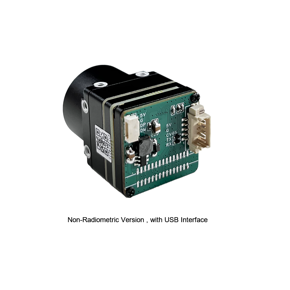
Engineered specifically for SWaP-critical robotic systems and tactical multi-rotor platforms, the Mini 640 delivers crisp thermal imaging and stable, low-noise performance within an extraordinarily compact 21mm × 21mm mechanical chassis. Featuring an active array resolution of 640×512 (with an optional 640×480 configuration), it natively supports a massive optical matrix spanning from wide-angle 5mm lenses up to 150mm super-telephoto Germanium optics. Its native USB UVC compliance guarantees deterministic, low-latency radiometric video transmission directly into Linux SBCs, autonomous drone autopilots, and edge-AI compute clusters.
- ✅ Матрица в фокальной плоскости: 640×512 uncooled VOx microbolometer with sub-40mK NETD sensitivity.
- ✅ Physical Dimensions: Ultra-miniature 21mm × 21mm cross-section weighing under 20 grams.
- ✅ Lens Compatibility: Comprehensive Germanium lineup: 5mm, 9mm, 13mm, 18mm, 35mm, 50mm, 75mm, 100mm, and 150mm.
- ✅ Transport Layer: Industrial USB UVC supporting continuous 16-bit radiometric raw streaming.
Неохлаждаемый мини 384*288 тепловизионный модуль камеры для дронов
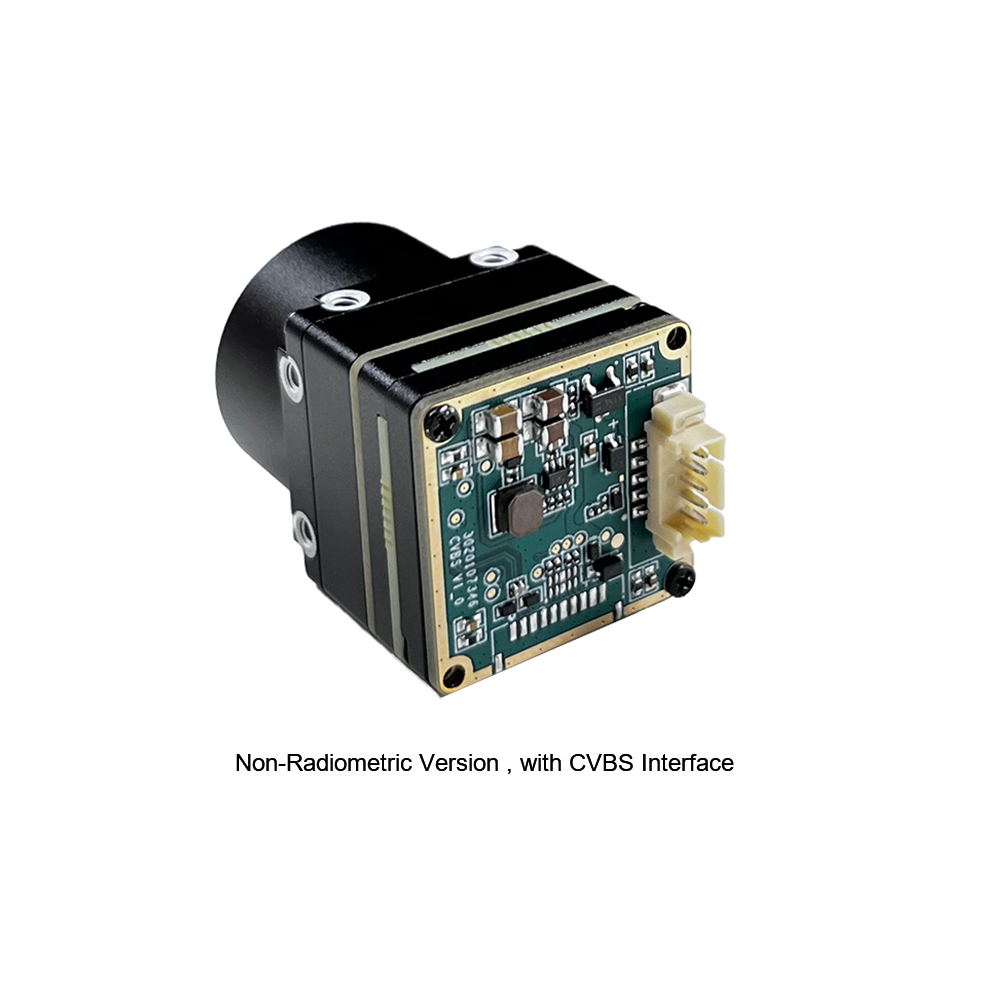
The MINI series 384×288 thermal imaging module is a high-precision, small-sized, and universal online temperature measurement engine engineered for industrial inspection and autonomous airborne observation. Utilizing high-stability uncooled detectors, it combines robust radiometric calibration curves with multiple hardware interface outputs, including CVBS analog and multi-pin digital options. Its compact footprint makes it a preferred solution for aerial plant maintenance, intelligent manufacturing, powerline inspection, and compact robotic payloads.
- ✅ Матрица в фокальной плоскости: 384×288 uncooled high-stability infrared detector for lightweight observation.
- ✅ Functionality: Calibrated online non-contact temperature measurement with spot and area tracking.
- ✅ System Interfaces: Composite CVBS analog, multi-pin digital expansion headers for custom PCB tie-ins.
- ✅ Deployment Sectors: UAV aerial inspection, utility line audits, equipment maintenance, and indoor mobile robotics.
7. High-Density Technical FAQ
Can I stream real-time 640x512 radiometric video directly to a Raspberry Pi or Linux SBC via USB?
How does this module perform compared to low-cost 640 thermal cores on AliExpress?
Is this 640x512 USB thermal core suitable for custom drone gimbals and DIY optical builds?
📚 Ссылки и дополнительная литература
- Отраслевой стандарт: Precision Interconnect Solutions & Board-to-Board Hardware: Amphenol
- Отраслевой стандарт: High-Reliability Micro-Ribbon & Data Interface Architectures: Molex
- Связанное руководство: Core Integration Methodology & Hardware Design: Przewodnik integracji rdzenia kamery termicznej
- Связанное руководство: Aerial Thermal Payload Applications in Wildlife & Environmental Tracking: Technologia termowizyjna UAV pomaga w badaniach i ochronie dzikich zwierząt
- Связанное руководство: Cost vs. Industrial Performance Matrix for Embedded Thermal Imaging Modules: Tanie kamery termowizyjne moduł: profesjonalna wydajność i niezawodna funkcjonalność