








Ultimate Guide to Thermal Module Camera Integration: 384x288 Solutions for Drones, Raspberry Pi & B2B OEM Projects
2026年7月1日
Best Thermal Camera Module for Drone Integration: Guide for B2B OEMs
2026年7月2日
Thermal True IR Night Vision Camera Module: B2B Integration Guide
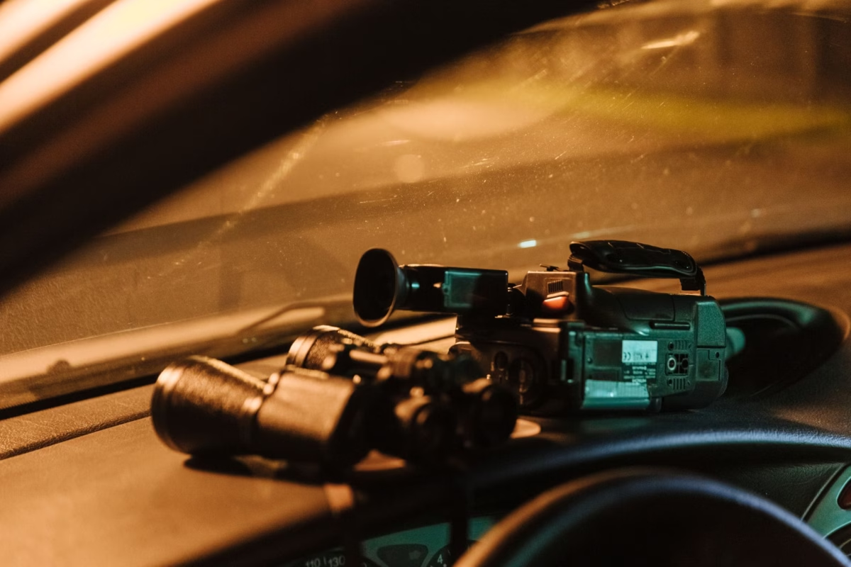
Look, if you are designing electro-optical systems for defense, industrial monitoring, or unmanned aerial platforms, you know that zero-light conditions are where cheap consumer gear falls apart. Here is the deal: traditional night vision gear relies on active near-infrared (NIR) illuminators. It acts like a beacon to anyone else with tactical equipment, and it gets completely choked out by fog, smoke, or dust. On the other hand, heavy-duty tactical and industrial builds require passive, long-wave infrared (LWIR) sensing that does not depend on a single reflected photon. Integrating a high-precision thermal true IR night vision camera module into your commercial payload bridges the gap between raw thermal capturing and high-speed edge processing. This guide outlines the real-world mechanics, hardware layouts, interface protocols, and deployment blueprints you need to integrate uncooled thermal cores into mission-critical hardware setups.
Table of Contents
- 👉 1. The Physics of True IR Sensing vs. Active NIR Night Vision
- 👉 2. Hardware Architecture of Uncooled Thermal Modules
- 👉 3. Interface Protocols and Electronics Integration
- 👉 4. B2B Product Showcase & Comparison Engine
- 👉 5. Multi-Sensor Optical Fusion and Drone Deployment
- 👉 6. Exhaustive Technical & Integration FAQ
1. The Physics of True IR Sensing vs. Active NIR Night Vision
In the design shop, you can't afford to confuse infrared bands. Active Near-Infrared (NIR) systems run in the 0.75 μm to 1.4 μm range. They are basically standard optical sensors with the IR cut filter stripped off. To see anything in absolute darkness, they require an active physical emitter—typically an 850nm or 940nm IR LED. This wavelength is highly vulnerable to atmospheric absorption, and its light bounces off moisture, fog, and smoke, creating a blinding wash of backscattered glare. Furthermore, in tactical situations, running an active NIR illuminator is like wearing a glowing neon sign. Anyone else with a simple silicon-based vision system can spot you from miles away.
Short-wave Infrared (SWIR) platforms operating in the 1.4 μm to 3.0 μm band are excellent for cutting through atmospheric haze and reading reflected light signatures, but they still depend on ambient photons (like nightglow or starlight) to resolve a target. True thermal infrared capture is a completely different ballgame. A professional-grade thermal true IR night vision camera module operates exclusively in the Long-Wave Infrared (LWIR) band, from 8.0 μm to 14.0 μm. Instead of looking for reflected light, we are tracking absolute blackbody radiation emitted directly by any physical object with a temperature above absolute zero (0 Kelvin or -273.15°C).
The raw physics here are absolute. Real-world emission profiles are dictated by Planck's law, which details the spectral distribution of electromagnetic energy emitted by an idealized blackbody in thermodynamic equilibrium:
In this equation, h represents Planck's constant, c is the speed of light in a vacuum, k is the Boltzmann constant, T is the target surface temperature in Kelvin, and λ is the wavelength of the emitted energy. To understand where the peak of this thermal radiation sits, we look to Wien's Displacement Law. This law dictates that as an object's temperature drops, its peak energy emission shifts toward longer wavelengths:
Where Wien's displacement constant b is approximately 2897.77 μm·K. If you do the math for a human target or standard terrestrial hardware sitting at a mean temperature of 300 K (about 27°C or 80°F), the peak energy wavelength lands at approximately 9.66 μm. This sits right in the center of the LWIR atmospheric absorption window, where air is highly transmissive. As a result, passive thermal energy passes directly through thick smoke, airborne dust, heavy mist, or complete darkness without scattering. Since the sensor is purely passive, there is zero physical or electromagnetic signal emitted from your hardware. For a deeper breakdown of the optics at work here, you can review the fundamental thermal imaging principle.
2. Hardware Architecture of Uncooled Thermal Modules
In the real world, you cannot use standard optical glass or basic CMOS architectures to build a thermal true IR night vision camera module. Standard silicon-based visible light sensors are blind to wavelengths beyond 1.1 μm, and normal glass completely absorbs thermal LWIR light. To build a functional thermal sensor, we use a specialized, uncooled microbolometer array paired with Germanium lenses designed for maximum transmission.
At the heart of an uncooled core is a micro-electromechanical systems (MEMS) sensor array. Each pixel in the array consists of a tiny absorber membrane suspended above a silicon substrate by thin mechanical legs. This design creates a high thermal resistance path between the pixel and the chip. When incoming LWIR radiation strikes the absorber membrane, the material heats up. This temperature shift alters its electrical resistance, which is measured by a Read-Out Integrated Circuit (ROIC) bonded under the active silicon array.
When evaluating OEM thermal cores, you will run into two primary detector materials. Here is how they stack up in real-world applications:
- Vanadium Oxide (VOx): VOx is the gold standard for high-performance defense, aerospace, and tactical systems. It has a high Temperature Coefficient of Resistance (TCR), typically ranging from -2.0% to -3.0% per Kelvin at room temperature. This high TCR translates directly to superior electrical sensitivity, lower overall system noise, and a very stable 1/f noise corner. If you are designing for long-range targets or challenging outdoor conditions, VOx is the material you want.
- Amorphous Silicon (a-Si): a-Si arrays are manufactured using standard silicon fabrication lines, which helps lower their production costs. They provide extremely uniform pixel responses across the array, but they suffer from a slightly higher noise floor and longer thermal time constants compared to VOx. This means they are best suited for high-volume commercial, industrial, or entry-level perimeter security layouts where budget is the primary driver.
Another key specification is the pixel pitch—the physical spacing between the centers of adjacent pixels. The industry standard used to hover around 17 μm, but modern uncooled thermal sensors have transitioned to 12 μm and 10 μm pixel structures. Shrinking the pixel pitch allows you to pack more resolution onto a smaller, lighter silicon die. From an optics perspective, this has a massive benefit: a 12 μm sensor can capture the exact same Field of View (FOV) as a 17 μm sensor using a much smaller, lighter Germanium lens. This design approach significantly reduces payload weight and volume, making it easier to integrate uncooled cameras into compact, stabilized gimbals.
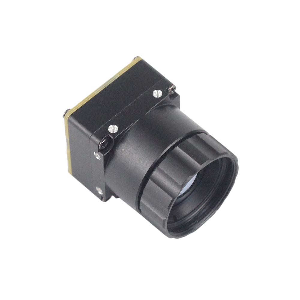
To evaluate image performance, system engineers track key metrics like Noise Equivalent Temperature Difference (NETD). Typically expressed in millikelvins (mK), NETD represents the smallest temperature change a thermal core can distinguish from its own electronic noise. A high-performance uncooled sensor targets an NETD of 40 mK or lower (measured with a fast f/1.0 lens). Additionally, because standard glass reflects and absorbs LWIR energy, uncooled modules require specialized anti-reflective (AR) coated Germanium lenses. When sourcing optical assemblies, industrial system designers turn to specialized component suppliers like Rising Optics to ensure maximum transmission performance and long-term durability in challenging environments.
3. Interface Protocols and Electronics Integration
When integrating a thermal true IR night vision camera module into a multi-sensor platform or an aerial gimbal, choosing the right interface is critical for control, transmission speed, and thermal stability.
For high-performance digital designs, you should use the MIPI CSI-2 (Mobile Industry Processor Interface Camera Serial Interface 2) protocol. This protocol connects your thermal core directly to host processors (like Rockchip SoCs, Nvidia Jetson Modules, or custom FPGAs) over high-speed differential lanes. This approach bypasses the processing overhead, USB stack latencies, and conversion delays of older setups. The host processor can access the raw, uncompressed 14-bit or 16-bit digital radiometric stream with sub-millisecond latency, making it easy to run automated temperature analysis, spatial edge filtering, and real-time AI object detection straight from the video feed. When designing high-speed MIPI digital boards, you must routing differential signal traces with a tight 100-Ohm matched impedance, keeping trace skew below 0.15mm to avoid data corruption.
For long-range analog transmission or legacy systems, the CVBS (Composite Video Baseband Signal) protocol remains highly useful. CVBS converts the internal thermal video stream into a single analog PAL or NTSC channel, allowing the video signal to be routed directly to FPV transmitters, mission control monitors, or legacy hardware without digital packing overhead. While CVBS cannot carry absolute radiometric data (raw digital pixel values) and limits the video resolution to standard definition, its analog nature ensures practically zero latency and robust signal decay characteristics across long cable runs.
PCB Design Checklist for Custom MIPI System Integration:
- ⚙️ Differential Routing: Router MIPI clock and data traces as tightly controlled 100-Ohm differential structures over an unbroken, solid ground plane. This design provides clean return paths and minimizes EMI.
- ⚙️ Skew Alignment: Ensure differential path pairs are length-matched to within 0.15mm of each other to prevent high-frequency clock misalignment.
- ⚙️ Power Plane Separation: Power the uncooled sensor biases using low-noise, ultra-stable Low-Dropout Regulators (LDOs). Keep high-speed switching digital lines far away from the sensitive analog reference voltages.
- ⚙️ Decoupling Capacitor Placement: Place high-frequency decoupling capacitors directly under the ROIC power pins to decouple digital switching noise before it reaches the sensor array.
- ⚙️ Physical Micro-Connectors: Use rugged, micro-pitch board-to-board connectors from trusted manufacturers like Hirose Electric to maintain secure electrical connections on vibrating drone or industrial platforms.
4. B2B Product Showcase & Comparison Engine
To help B2B system planners, payload engineers, and procurement managers select the best hardware setup, we examine two uncooled thermal modules optimized for unmanned platforms, industrial mapping, and continuous security deployments.
Uncooled Infrared Mipi 640 384 256 9mm Thermal Imaging Camera Module For Drones

This miniature, uncooled infrared thermal imaging module is designed specifically for lightweight drone gimbals, micro-sensor payloads, and compact tracking equipment. It delivers sharp, high-contrast imagery using a modern uncooled microbolometer sensor. By utilizing a high-density 12 μm pixel pitch and flat, lightweight 9mm Germanium lenses, the module reduces overall configuration volume and mass while maintaining a wide field of view. Its direct MIPI interface provides low-latency digital transmission, making it ideal for real-time edge processing and AI calculations.
- ✅ High Sensitivity: Sharp thermal contrast and clear object boundaries for locating heat signatures in complete darkness or dust.
- ✅ Optimized SWaP Profile: Decreased sensor size minimizes lens weight, reducing burden on gimbal motors.
- ✅ Direct Digital Integration: Uses MIPI interfaces to feed raw thermal streams straight to the host processor, bypassing processing latency.
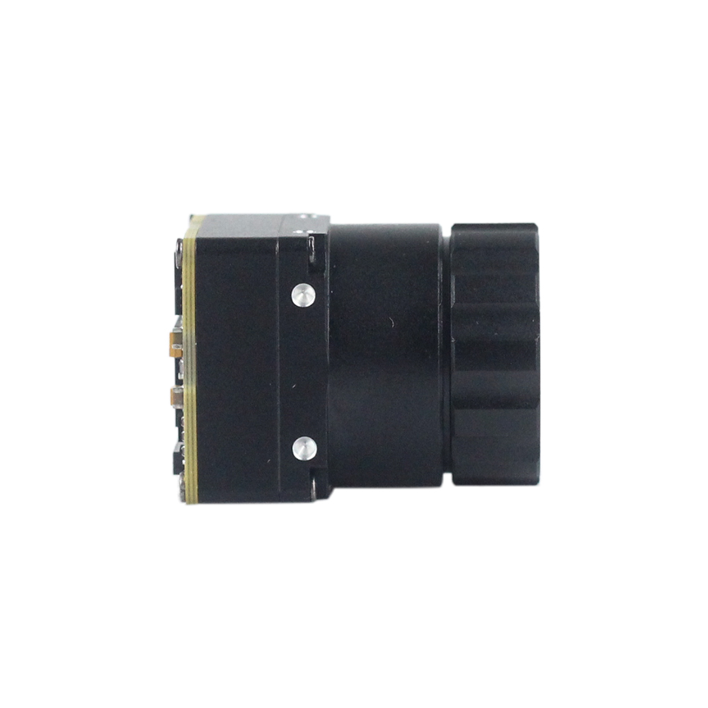
Uncooled Mini 384*288 Thermal Camera Module For Drones
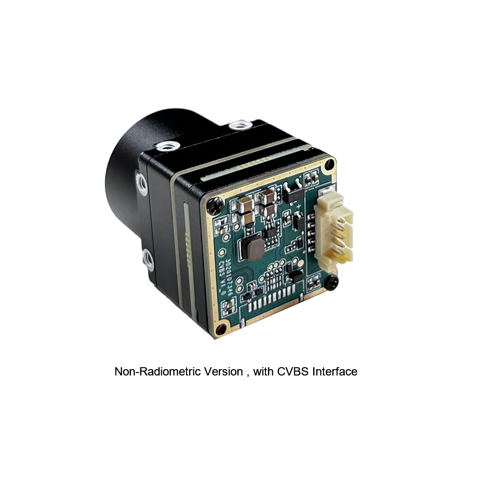
The MINI series uncooled thermal core functions as a high-precision, small-sized, universal online temperature measurement module. Equipped with an array of communication options—including CVBS analog output, standard serial UART control lanes, and digital outputs—this module is suited for complex integration projects. Key application areas include machine vision, safety inspections, automated predictive maintenance, robotic platforms, and lightweight drone payloads, where precise temperature mapping is required.
- ✅ Dual-Performance Capability: Combines reliable temperature diagnostics with zero-light passive imaging.
- ✅ Flexible Connectivity: Outfitted with multiple physical interfaces to simplify integration with analog telemetry transmitters and serial controllers.
- ✅ Broad Operational Versatility: Suitable for machine vision, security, predictive maintenance, and robotic platforms.
Comparative Integration Specifications
| Technical Parameters | Uncooled MIPI 640/384/256 Module | Uncooled MINI 384x288 Module |
|---|---|---|
| Resolution Profiles | 640x512, 384x288, or 256x192 adaptive array selections | 384x288 native array resolution |
| Pixel Pitch Size | 12 μm (supports smaller, lighter optics) | 17 μm (delivers robust radiometric stability) |
| Focal Optics | 9 mm AR-Coated Germanium primary lens | Adjustable sub-10mm specialized variations |
| Primary Interfaces | MIPI CSI-2 (direct raw video) | Analog CVBS + USB support + Digital UART control lines |
| Radiometric Function | Optimized for dynamic situational tracking | Configured for online temperature measurement |
| Target Integration Use | Weight-critical drone gimbals, advanced tracking engines | Predictive maintenance, telemetry systems, industrial machinery |
5. Multi-Sensor Optical Fusion and Drone Deployment
Let's talk about multi-spectral integration. While thermal LWIR is unmatched at locating targets through smoke or total darkness, it lacks fine spatial edge details. For instance, a thermal sensor cannot read vehicle license plates or identify written signs. To resolve this, modern tactical payloads pair the thermal core with a high-resolution visible-light CMOS sensor or digital NIR sensor. This approach uses multi-spectral video fusion to capture high-frequency physical details and overlay them directly onto the thermal image matrix.
To run sensor fusion, the system processor must resolve the physical distance between the two sensor lenses. This is achieved by running coordinate mapping transforms to scale, shift, and match the field of view. By aligning the fields of view, the processor can map the sensors' pixels on a 1-to-1 basis:
In this equation, α and β are dynamic parameters adjusted by image processing algorithms to balance thermal contrast and high-frequency edge detail based on situational lighting levels.
When mounting uncooled thermal modules onto drone gimbals or compact pan-tilt-zoom (PTZ) platforms, managing Size, Weight, and Power (SWaP) budgets is essential. Let’s break down the priorities:
- ⚠️ Weight Management: Every gram saved on the sensor assembly reduces load on micro-gimbals, lowering motor current draw and power consumption. Opting for a 12 μm sensor (such as the uncooled MIPI 640 module) allows engineers to use smaller, lighter Germanium lenses to capture identical FOVs, helping to maintain stable flight dynamics.
- ⚠️ Thermal Dissipation: Because microbolometers are highly sensitive to internal operating temperatures, high-vibration flight environments can cause thermal drift. System designers must isolate physical heat dissipation paths from the lens mounts and include dynamic non-uniformity correction (NUC) algorithms to protect image quality from heat generated by motor drivers or onboard processors.
- ⚠️ Electromagnetic Shielding: Brushless gimbal motors generate high-frequency electromagnetic interference. Designers should shield sensitive signal paths, match differential trace lengths, and use low-noise power distribution networks to prevent raw digital image data corruption.
For B2B security operations requiring complete, long-range coverage, integrating compact thermal cores into dual-sensor platforms yields continuous tracking capabilities. For example, using specialized modules within a network of PTZ dual-sensor thermal imaging camera systems provides secure, continuous perimeter surveillance. Integrating these cores into integrated spherical thermal PTZ camera systems enables long-range automated fire detection, perimeter guard automation, and rapid target tracking. These systems leverage robust PTZ hardware to protect infrastructure from remote locations, minimizing overall equipment footprint and integration costs.
6. Exhaustive Technical & Integration FAQ
What is the differences between active NIR night vision, SWIR photography, and a thermal camera module?
Can I pair a thermal camera module with a digital night vision sensor for optical fusion?
What are the key specs to evaluate in an OEM thermal camera module?
- Resolution: Standard resolutions include 640x512, 384x288, and 256x192. Higher resolutions provide more pixels on-target, extending detection, recognition, and identification (DRI) ranges.
- Pixel Pitch: Choosing a 12 μm detector over a 17 μm detector enables the use of smaller, lighter optics while keeping the same field of view. This reduces overall system weight and volume.
- Noise Equivalent Temperature Difference (NETD): This parameter measures the sensor's thermal sensitivity. An NETD of ≤ 40 mK resolves finer temperature differences than a ≤ 50 mK sensor, providing cleaner images in areas with minimal temperature variation.
- Interface Protocol Compatibility: If you are integrating with an AI edge-processing unit, choose a direct low-latency interface like MIPI CSI-2 to keep transmission delays minimal. For analog transmitters or legacy systems, choose a CVBS connection.
- Shutter Settings (NUC Calibrations): Uncooled microbolometers require periodic non-uniformity correction (NUC) to compensate for internal temperature drift. Ensure the core supports a configurable internal shutter or a shutterless correction algorithm suitable for your mission-critical applications.
How do I manage and mitigate thermal drift in uncooled microbolometer camera modules?
What focal length is required to detect a human target at 1000 meters?
f = (Distance * Pixel_Pitch) / Target_Width
Using a 12 μm pixel pitch sensor and assuming a standing human target width of 1.8 meters, detecting a person at 1000 meters requires a spatial focal length of at least 6.67mm. To ensure reliable performance under unfavorable weather conditions (such as high humidity or atmospheric attenuation), using a 9mm lens provides an engineering safety margin that ensures clear target detection at 1000 meters.
📚 References & Further Reading
- Industry Component Standard (Connector Pinouts): Documentation on physical micro-coaxial board-to-board connectors is available through Hirose Electric.
- Optical Coatings & Lens Assembly: Details on AR-coated Germanium optical assemblies are available from Rising Optics.
- Dual-Sensor Deployment Guide: Review structural setups in the B2B guide for PTZ Dual-Sensor Thermal Systems.
- Wide-Area Security Infrastructure: Analyze integration examples with Spherical PTZ Cameras.
- Thermal Imaging Core Physics: See the detailed primer explaining the baseline thermal imaging principle.





