









Thermal True IR Night Vision Camera Module: B2B Integration Guide
2026年7月1日
How to Choose the Best Infrared Thermal Imaging Camera Module for Drones, Raspberry Pi, and Edge AI Integration
2026年7月3日
Best Thermal Camera Module for Drone Integration: Guide for B2B OEMs
Look, the commercial drone sector is undergoing a massive shift. I’ve spent years in the shop watching engineers pull their hair out trying to wedge proprietary, locked-down payload ecosystems into custom hulls. Here's the deal: those days of paying enterprise-tier ransoms for closed platforms are over. OEM engineers, system integrators, and industrial innovators are actively moving away from proprietary, locked-down payload ecosystems toward open, modular architectures. The ability to capture mid-wave or long-wave infrared thermal signatures from an aerial platform is no longer reserved for military operations or enterprise-tier budgets. Today, high-resolution uncooled thermal cores are integrated directly into custom UAVs (unmanned aerial vehicles) to perform industrial tasks such as high-voltage utility inspection, agricultural analysis, search and rescue (SAR), and automated security monitoring.
For B2B OEMs, selecting a thermal camera module drone payload requires balancing complex engineering tradeoffs. This isn't just about picking a sensor off a spec sheet; it's about understanding how every gram, milliwatt, and line of code impacts the performance of your aircraft. This industrial blueprint explores the technical parameters of thermal integration, detailing the relationships between pixel pitch, thermal sensitivity (NETD), SWaP-C (Size, Weight, Power, and Cost) constraints, and communication interfaces. By understanding the electrical, mechanical, and optical interfaces of miniature Long-Wave Infrared (LWIR) modules, system designers can bypass expensive commercial packaged systems and deploy highly reliable, customized thermal imaging drones.
Table of Contents
- 👉 1. Industry Landscape: The Shift to Modularity in Drone Thermography
- 👉 2. Critical Technical Parameters for Drone Thermal Modules
- 👉 3. SWaP-C Architectural Optimization for UAV Payloads
- 👉 4. Hardware & Software Interface Integration Protocols
- 👉 5. Featured B2B OEM Thermal Modules: Technical Evaluation
- 👉 6. Comparative Technical Specifications Matrix
- 👉 7. Step-by-Step OEM Integration Workflow
- 👉 8. Deep-Dive OEM FAQ Profile
- 👉 9. Structural Summary for B2B Purchasing Managers
1. Industry Landscape: The Shift to Modularity in Drone Thermography
Historically, integrating thermal imaging into an aerial fleet required procuring closed, proprietary thermal payloads from single-source providers. These locked systems offered minimal configuration options, forced engineers into restrictive software ecosystems, and cost thousands of dollars per unit. Modern B2B developers are breaking away from these closed ecosystems. By selecting independent, board-level thermal camera cores, engineers can design custom payloads tailored for specific applications, such as machine vision, infrastructure inspections, and robotics.
Integrating a lightweight uncooled LWIR sensor into an open-source flight platform or an industrial heavy-lift drone allows developers to maintain complete control over data pipelines, proprietary analysis algorithms, and telemetry loops. Ground control stations running QGroundControl or Mission Planner can easily digest custom MAVLink messages packed with regional temperature data. OEMs can refer to the comprehensive 2025 Thermal Module Guide to understand how mini detector platforms can reduce upfront R&D costs and accelerate time-to-market. By checking out the details of manufacturing and design philosophies through our About Us page, platform designers can identify the extensive engineering resources available for custom aerospace projects.
THERMAL IMAGING REAL-TIME VIDEO
2. Critical Technical Parameters for Drone Thermal Modules
Selecting the optimal core for a professional thermal drone payload requires understanding key optical and sensor characteristics. These parameters impact image clarity, measurement precision, flight range limits, and analytical depth. Let's strip away the marketing speak and look at the actual physics driving these components.
2.1 Spectral Bands: LWIR vs. MWIR in Aerial Operations
For aerial applications, selecting the appropriate electromagnetic spectrum is critical:
- LWIR (Long-Wave Infrared, 8–14 μm): Typically powered by uncooled microbolometers. These sensors do not require mechanical cryocoolers, which dramatically lowers their cost, size, and weight. They operate within the peak atmospheric transmission window for ambient terrestrial temperatures (-20°C to +150°C, and up to +550°C with industrial calibration). This makes them the undisputed industry standard for search and rescue, agricultural monitoring, and power line inspections.
- MWIR (Mid-Wave Infrared, 3–5 μm): Typically utilizes cooled detectors (InSb or MCT). While they offer excellent contrast and long-range performance through moisture-heavy air, the requirement for a cryogenic cooler adds significant weight, power demand, cost, and mechanical wear. Unless you are building high-altitude military-reconnaissance drones or zero-tolerance offshore gas-plume monitoring rigs, stay away from MWIR. It is an engineering and budgeting headache.
For the majority of commercial, civil, and industrial drone designs, uncooled LWIR represents the sweet spot for budget and system complexity.
2.2 Pixel Pitch, Resolution, and Target Detection (Johnson's Criteria)
The capability of an airborne thermal camera to resolve targets at range is determined by its resolution, pixel pitch, and focal length. Here is how these interact under real-world conditions:
- Resolution: Common configurations include entry-level 384 x 288 cores and high-definition 640 x 512 arrays. Higher resolutions provide more pixels on target at greater flight altitudes, allowing drones to fly safer, higher paths while maintaining data integrity. In the field, a 640-class thermal core lets you cover four times the area in a single pass compared to an older 336 or 160 core.
- Pixel Pitch: Typically measured in micrometers (μm) (e.g., 17μm or 12μm). A smaller pixel pitch allows a smaller optical sensor to capture equivalent spatial details, reducing both physical lens size and overall weight. By moving from 17μm down to 12μm, we can scale down the focal length of the Germanium lens while maintaining the same Field of View (FOV). This is a massive win for saving weight.
- Johnson’s Criteria: System integrators use these criteria to calculate drone flight profiles and safety margins:
- Detection: Is an object present? (Requires 1.5+ pixels across the minimum dimension of the target).
- Recognition: What class of object is it (e.g., vehicle vs. human)? (Requires 6+ pixels across the target).
- Identification: Can specific details be resolved (e.g., identifying a specific piece of machinery)? (Requires 12+ pixels across the target).
The Instantaneous Field of View (IFOV), which correlates directly to the spatial resolution at any given altitude, can be computed by dividing the sensor's physical pixel pitch by the focal length of the optical lens assembly. Increasing the focal length narrows the field of view but vastly boosts the distance at which an engineer can comfortably execute target identification according to Johnson's Criteria. Let's look at the math: if you are running a 12μm pixel pitch sensor with a 13mm lens, your IFOV is approximately 0.92 milliradians. At a flight altitude of 100 meters, your spatial resolution (Ground Sample Distance) is 9.2 cm per pixel. This means you can easily detect a human (roughly 0.5m across, covering about 5.4 pixels) but you'll struggle to identify what they're holding without dropping altitude or tightening your lens setup.
2.3 Thermal Sensitivity (NETD) and Temperature Accuracy
Noise Equivalent Temperature Difference (NETD) defines a sensor's thermal sensitivity, measured in millikelvins (mK). It represents the temperature difference that yields a signal-to-noise ratio of one:
- ≤ 40 mK or ≤ 50 mK: High-performance sensors can distinguish minute differences in thermal energy. This is critical when analyzing low-contrast scenes, such as looking for a lost hiker in cold, rain-slicked terrain, identifying subtle moisture variations in agricultural fields, or isolating minor thermal anomalies in high-voltage insulators.
- Temperature Measurement Accuracy: True thermographic industrial modules support real-time radiometric measurements across the frame. Standard systems achieve accuracies of ±2°C or ±2%, which is critical for industrial applications where identifying the exact temperature of an oil pipe or a substation transformer determines whether you send a crew to repair it immediately or log it for routine maintenance.
3. SWaP-C Architectural Optimization for UAV Payloads
Every ounce of weight on a drone represents battery power burned just staying airborne. Optimizing Size, Weight, Power, and Cost (SWaP-C) isn't just a goal; it's the defining constraint of drone engineering. If your payload is too heavy, your flight time drops below operational viability. If it's too power-hungry, you run the risk of premature battery failure or overheating your avionics bay. Let's look at how to properly design around these limitations.
3.1 Weight Constraints and Center of Gravity (CoG)
For multirotor and fixed-wing aircraft, weight directly impacts battery cycle life and flight times. Excess payload mass on a gimbal assembly increases motor load, reduces response speeds, and shortens operational windows.
- Miniaturized Cores: Modern uncooled cores measure as little as 21 mm * 21 mm and weigh less than 50 grams (excluding the lens assembly). This is a game-changer for drone designers because it frees up weight budget for robust gimbal stabilization.
- Center of Gravity (CoG): Keeping the physical footprint compact minimizes the torque required by the gimbal motors, allowing for more stable, jitter-free video feeds even during high-speed maneuvers. If you mount a long, front-heavy telephoto lens on a tiny thermal sensor without sliding your mounting bracket to rebalance the physical axis, your pitch motor will overheat in minutes.
3.2 Thermal Dissipation and Power Consumption
Miniature thermal sensors can generate internal heat that degrades performance if not managed properly. Because uncooled microbolometers rely on measuring temperature differentials across pixel arrays, thermal drift inside the camera housing is your worst enemy.
- Power Consumption: Keeping power draw below 1.5 W prevents excessive drain on the drone’s secondary power distribution board, ensuring your ESCs (Electronic Speed Controllers) have all the power they need for motor control.
- Heat Dissipation: Thermal engineers should couple the core’s aluminum chassis to the drone’s frame or gimbal arm using high-conductivity thermal interfaces (such as those from Amphenol). Active flight-line airflow can also be routed to passive cooling fins on the module enclosure to maintain a stable operating temperature. By utilizing the downdraft of your drone's propellers, you can create a highly effective passive cooling loop without adding heavy, power-hungry fans.
For additional integration context, refer to our Integrated Thermal Camera Selection Guide, which covers matching thermal performance with overall system profiles.
4. Hardware & Software Interface Integration Protocols
Establishing reliable connection lines between the sensor payload, flight controller, and ground-station datalink is critical for automated airborne applications. If your communications protocol exhibits high latency or is prone to interference, your expensive thermal core becomes practically useless in the field.
4.1 Video Outputs: CVBS, USB, and Digital Streams
Extracting thermal video from a camera module requires selecting a compatible interface standard based on your payload configuration:
| Interface Type | Bandwidth / Latency | Typical Physical Connector | Target Application |
|---|---|---|---|
| CVBS (Analog) | Low resolution, zero lag (< 10 ms) | Miniature coaxial pin header (e.g., MMCX) | Analog FPV transmitters for search and rescue |
| USB 2.0 / 3.0 | High bandwidth, raw digital stream | Micro-USB / USB Type-C | Direct connection to onboard processors for edge AI |
| Digital (MIPI-CSI / LVDS) | Ultra-high bandwidth, raw pixel-level data | Flexible Flat Cable (FFC) | Custom companion computer systems for image analysis |
4.2 Control Interfaces: UART, I2C, and SDK Integration
Configuring dynamic parameters like palette colorization, digital zoom, and NUC (Non-Uniformity Correction) requires a robust control interface:
- UART / TTL: Operating at standard baud rates (e.g., 115200 bps), UART interfaces are ideal for communicating with flight controllers running Ardupilot, PX4, or custom architectures. This allows you to map thermal settings to physical buttons on an operator's handheld transmitter.
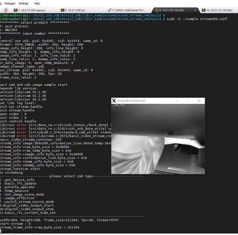
- SDK Support: High-quality OEM thermal modules include mature SDK libraries for Linux and Windows platforms. These libraries handle raw A/D conversion, transform pixel values into temperature values, and manage thermal measurement zones directly on onboard companion computers such as Raspberry Pi, Jetson Nano, or JM Chip processing nodes. An efficient SDK is the difference between writing custom analysis code in a weekend or spending three months trying to manually parse raw 14-bit CMOS packet data.
5. Featured B2B OEM Thermal Modules: Technical Evaluation
When selecting hardware for industrial integration, you need to look at real-world components. Let's dive deep into two highly optimized, board-level LWIR cores designed specifically for miniature payloads.
5.1 Uncooled Mini 384*288 Thermal Module
The Uncooled Mini 384*288 Thermal Camera Module For Drones is configured for weight-sensitive applications requiring precise real-time temperature tracking.
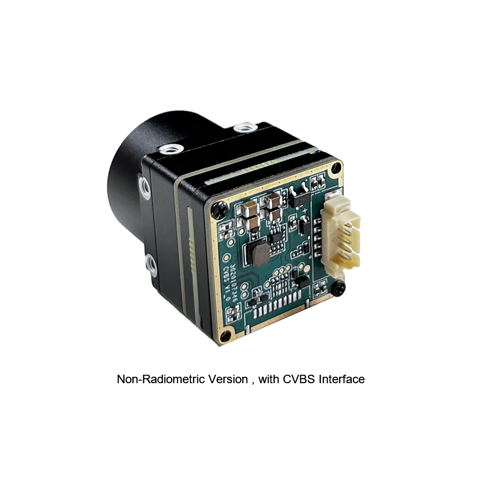
The MINI series infrared thermal imaging temperature measurement module is a high-precision, small-sized, and universal online temperature measurement infrared thermal imager. It uses high-quality detectors, high resolution, stable performance, and powerful functions. It is equipped with multiple interfaces, making it a preferred product in application fields such as machine vision, safety inspection, intelligent manufacturing, equipment maintenance, robot drone airborne, and so on. In the shop, we love this little core because of its extreme value-to-performance ratio; it is incredibly simple to wire up and balance on lightweight, 2-axis micro-gimbals.
| Technology Specification | Value Details |
|---|---|
| Sensor Type | Uncooled FPA Microbolometer (Vanadium Oxide) |
| Resolution | 384 * 288 |
| Integration Target | UAV payload/Machine Vision/Robotics |
| Temperature Analysis | On-line real-time radiometric mapping |
5.2 Uncooled LWIR USB Mini 640*512 Module
The Uncooled LWIR USB Mini 640*512 Thermal Imaging Camera Core Module delivers higher spatial resolution for demanding aerial missions, such as long-range utility inspections, regional mapping, and complex search-and-rescue operations.

Mini uncooled infrared thermal imaging module features in sharp and crisp image presentation, compact size and low cost. Mini-Size of 21mm*21mm, 5/9/13/18/35/50/75/100/150mm, 640*480 resolution optional, stable performance and strong environmental adaptability. If you are designing a flagship inspection model that needs to clearly evaluate transmission lines from a safe flying distance, this is your solution. It provides the crisp optical clarity required to spot loose connections or failing isolators from fifty meters out.
| Technology Specification | Value Details |
|---|---|
| Footprint Area | Ultra-compact 21mm * 21mm |
| Lenses Available | 5 / 9 / 13 / 18 / 35 / 50 / 75 / 100 / 150mm Germanium Optics |
| Core Resolution | 640 * 512 default options (640*480 optional) |
| Interfacing Architecture | USB-driven streaming (compatible with major OS platforms) |
6. Comparative Technical Specifications Matrix
For B2B engineering leads evaluating system design options, the following matrix compares the crucial hardware differences between our target thermal cores. Treat this as your quick-reference sheet when calculating payload weights and communication specs during initial CAD and electronic layout phases:
| Key Engineering Metric | Uncooled Mini 384*288 Thermal Core | Uncooled LWIR USB Mini 640*512 Core |
|---|---|---|
| Sensor Resolution | 384 * 288 Pixels | 640 * 512 (Optional 640 * 480) |
| Spectral Band | 8 ~ 14 μm (LWIR) | 8 ~ 14 μm (LWIR) |
| Pixel Pitch | 12 μm (Optimized Pixel Area) | 12 μm / 17 μm (Configuration Dependent) |
| Thermal Sensitivity (NETD) | ≤ 40 mK or ≤ 50 mK @ f/1.0 | ≤ 40 mK (High-Sensitivity Edition) |
| Temperature Range Support | -20°C ~ +150°C / High up to +550°C | -20°C ~ +150°C / Premium High Calibration |
| Physical Dimensions | Ultra-Mini Bare board profiles | 21mm * 21mm (Excluding Optics Frame) |
| Weight | < 45 g (Aperture/Lens Dependent) | < 50 g (Base Assembly) |
| Primary Video Outputs | Analog CVBS / Digital Native Stream | USB Interface / MIPI Digital Output |
| Control Formats | UART / I2C Configuration protocols | SDK-supported USB / UART commands |
| Optics Options | Prime and fixed micro lenses | Variable Focal Ranges: 5mm up to 150mm |
7. Step-by-Step OEM Integration Workflow
Integrating a board-level thermal module into a professional drone involves several hardware and software milestones. This workflow helps avoid common system design pitfalls. Take it from my scar tissue: skipping even one of these validation drills can lead to weird video distortions, blown circuits, or a shaky gimbal in flight.
Step 1: Mechanical Mounting and Vibration Isolation
⚙️ first, secure the 21 mm * 21 mm module within a protective enclosure or directly onto the gimbal assembly. Thermal cameras are sensitive to vibration, which can blur the image and strain mechanical connectors. Engineers should mount the thermal core using high-performance mechanical dampeners (such as silicone or rubber bushings) to isolate it from high-frequency vibrations caused by the drone's brushless motors.
Step 2: Electrical Engineering and Noise Isolation
⚙️ Next, route electrical lines back to a clean, isolated power distribution source. Thermal imaging modules require stable, noise-free current to maintain a clean raw signal. Do not connect the thermal module directly to the main Electronic Speed Controller (ESC) battery bus, as electrical noise from the motors can degrade image quality, manifesting as annoying diagonal lines across your video feed. Instead, power the camera using active, filtered Step-Down voltage regulators with proper LC filtering. Shielding all wires with physical braiding also prevents interference with the drone's telemetry links.
Step 3: Interface Wiring and Video Signal Paths
⚙️ Once power is established, connect the communication lines. For analog FPV (first-person view) systems, route the CVBS output directly into the drone's analog transceivers. For digital ecosystems, run high-speed USB or MIPI raw data cables to an onboard companion computer (such as an NVIDIA Jetson or Raspberry Pi) to enable real-time calculations or stream processing. Be mindful of cable length: high-speed digital lines like MIPI-CSI do not tolerate long runs unless they are converted via a serializer/deserializer pair (like GMSL).
Step 4: Software and Controller Initialization
⚙️ Integrate the module’s serial control (UART or I2C) with the drone’s flight management system. Developers can write drivers using the provided C/C++ or Python SDK to control features like color palettes, digital zoom, and Non-Uniformity Correction (NUC) directly from the ground control station using standard commands. Additionally, ensure the SDK is configured to trigger an automatic shutter calibration whenever the ambient temperature fluctuates beyond safe limits, or mapped to manual pilot control so it doesn't calibrate right when the drone is lining up an critical monitoring run.
Step 5: Calibration, Testing, and Flight Validation
⚙️ Finally, perform ground tests using physical reference points with known thermal signatures to calibrate the temperature measurements. Once static tests are successful, conduct test flights at varying altitudes to optimize lens focus, ground-level resolution, and gimbal panning performance. Validate that the drone's telemetry overlay (OSD) showing GPS coordinates and flight altitudes matches the precise location of the logged thermal events.
8. Deep-Dive OEM FAQ Profile
Can I integrate a third-party thermal camera module onto custom DIY or commercial drones, and what protocols are used?
How can I build an affordable thermal imaging drone without purchasing expensive premium packages?
9. Structural Summary for B2B Purchasing Managers
When selecting a thermal core for your engineering team, use these clean guidelines to match the hardware requirements to your budget and application profiles:
- ✅ Select the Mini 384*288 module for highly cost-sensitive, lightweight applications. This core is ideal for localized security, agricultural analysis, and drone systems with strict weight limit budgets. It is the perfect entry point for proving a thermal payload prototype.
- ✅ Select the Mini 640*512 module when spatial detail and inspection range are critical. This core is suited for high-altitude utility inspections, industrial asset classification, and systems using companion computers for automated target tracking. It gives you the necessary pixel density to fly safer, higher flight lines without sacrificing data acquisition capabilities.
📚 References & Further Reading
- Industry Standard: Reference developer notes from JM Chip page resources and connect physical backing structures with robust brackets from Amphenol.
- Related Guide: See our comprehensive 2025 Thermal Module Guide, read our core system comparisons on the Integrated Thermal Camera Selection Guide, or review our history on the About Us page.





