









Wholesales Portable Infrared Thermal Camera Module Mini: OEM Solutions
2026年7月15日
Buy 25mm Electronic Focusing Thermal Camera Module (640x512 VOx, 35mk, H.265/BT.656/CVBS) for UAVs & FPV
2026年7月16日

Best Tiny 256*192 CMOS Sensor Thermal Camera Module with Night Vision for DIY & OEM Systems
Modern tactical reconnaissance, search and rescue (SAR), and industrial automation demand high-efficiency thermal payloads with minimized SWaP-C (Size, Weight, Power, and Cost) footprints. While traditional night vision devices rely on ambient light amplification, long-wave infrared (LWIR) microbolometers detect emitted thermal radiation. Because of this, integrating an ultra-compact 256×192 thermal sensor core with night vision capabilities has become a vital engineering objective for drone manufacturers, security system integrators, and DIY hardware developers.
Selecting the ideal micro-thermal core requires balancing physical dimensions, pixel pitch, radiometric capabilities, and interface protocols. This comprehensive technical guide analyzes the design architecture, integration workflows, and product options for tiny 256×192 uncooled LWIR camera modules. Whether you are building custom thermal fusion goggles, lightweight drone payloads, or automated thermal monitoring systems, this blueprint provides the necessary engineering insights, software integration steps, and hardware comparisons to optimize your design.
Table of Contents
- 👉 1. Demystifying LWIR Microbolometers vs. Visible CMOS Sensors
- 👉 2. Key Specifications: Selecting the Ultimate 256×192 Thermal Module
- 👉 3. Hardware Integration & Interface Schematics (SPI, USB, RJ45)
- 👉 4. Software Integration, SDKs, and ASIC Image Processing
- 👉 5. Commercial-Grade Tiny 256×192 & High-Res Thermal Modules
- 👉 6. Thermal Night Vision Fusion System Architecture
- 👉 7. Mechanical, Electrical, and Optical Integration FAQ
1. Demystifying LWIR Microbolometers vs. Visible CMOS Sensors
In industry marketing and consumer documentation, the phrase "tiny 256*192 cmos sensor thermal camera module with night vision" is frequently used. From a precise physical and electronics engineering perspective, let's address a common technical misnomer. Silicon-based Complementary Metal-Oxide-Semiconductor (CMOS) sensors and LWIR microbolometers are radically different semiconductor technologies, utilizing completely distinct solid-state physics to capture electromagnetic radiation.
Here's the deal: standard visible-light and near-infrared (NIR) CMOS sensors rely on the photoelectric effect within silicon junctions. They detect photons in the 400nm to 1000nm wavelength range. These sensors are fundamentally reflective; they require an ambient or artificial light source to bounce photons off a target or environment. Look, without moon light, starlight, or active infrared illuminators, a visible CMOS sensor cannot resolve an image. This is a severe limitation in complete tactical darkness, heavy smoke, or deep airborne dust.
In contrast, long-wave infrared (LWIR) microbolometers operate in the 8µm to 14µm spectral band. Instead of measuring photon impacts directly to generate charge carriers, a microbolometer utilizes an array of micro-sized thermally sensitive material membranes suspended over a silicon readout integrated circuit (ROIC). When infrared radiation emitted by any object above absolute zero strikes these suspended membranes, the temperature of the material changes. This change alters the electrical resistance of the material, which is measured by the ROIC. Because this system measures emitted thermal energy rather than reflected light, it operates in complete darkness, cutting through atmospheric obstructions such as dense fog, heavy rain, foliage, and tactical smoke screens.
To explore the micro-fabrication techniques, material composition, and vacuum packaging requirements of these advanced thermal sensors, you can examine the historical and technical breakdown of the Wikipedia Microbolometer page.
2. Key Specifications: Selecting the Ultimate 256×192 Thermal Module
In the shop, evaluating a micro thermal camera core means looking past the marketing fluff. System engineers must evaluate several distinct electro-optical parameters to ensure the hardware survives real-world deployment:
Resolution and Pixel Array Configuration
A resolution of 256×192 active pixels yields a total of 49,152 unique thermal measurement points. In terms of pixel count, it occupies the middle ground between low-resolution thermal indicator arrays and high-resolution industrial arrays. This particular matrix size provides sufficient spatial resolution to recognize human targets at distances exceeding 100 meters while keeping data bandwidth and image-processing overhead low enough to run on basic microcontrollers and single-board computers.
Pixel Pitch (12µm vs. 17µm)
Modern thermal camera design has shifted toward a 12µm pixel pitch. This spatial scaling reduces the physical surface area of the sensor die. This reduction enables the optical assembly to be built with smaller and lighter germanium lenses while maintaining equivalent field-of-view parameters. For weight-sensitive aerospace applications and head-mounted tactical frames, this reduction in physical lens mass is a massive advantage.
Noise Equivalent Temperature Difference (NETD)
NETD represents the thermal sensitivity of the camera. It defines the minimum temperature difference that the sensor can distinguish from its own electronic noise. Typically measured in millikelvins (mK) at standard room temperature with an f/1.0 aperture, an NETD value of less than 50mK means the module can resolve temperature differences of less than 0.05°C. Lower NETD values yield higher image contrast and cleaner output video, allowing operators to distinguish subtle environmental features in low-thermal-contrast environments.
Frame Rate
Thermal camera frame rates are divided into two classifications: slow-frame-rate systems (usually capped at 9Hz to comply with international export controls) and high-frame-rate systems (operating at 25Hz, 30Hz, or 50Hz). Real-time night vision applications, dynamic target tracking, and drone flight navigation require a refresh rate of at least 25Hz to eliminate motion blur and input lag.
Spectral Band and Optics
A standard LWIR spectral response covering the range between 8µm and 14µm is necessary for terrestrial operations. At these wavelengths, the sensor relies on specialized, highly transmissive optics. Unlike visible-light sensors, thermal cameras require lenses built with materials such as germanium, silicon, or chalcogenide glasses to focus long-wave infrared energy onto the microbolometer array.
3. Hardware Integration & Interface Schematics (SPI, USB, RJ45)
Integrating a compact 256×192 thermal sensor module into a larger hardware system requires careful selection of both physical and logical communication interfaces. The choice of hardware connection determines the maximum attainable frame rate, control latency, and processing requirements of the host processor. Here is how we break down the integration paths in the lab:
SPI (Serial Peripheral Interface): For ultra-low-power systems or those driven by basic microcontrollers, SPI represents the standard bus interface. The thermal module operates as an SPI peripheral, feeding raw 14-bit or 16-bit digital temperature arrays directly to the host. You need to keep in mind that the host microcontroller must have an SPI clock speed of at least 24MHz to handle 49,152 pixels per frame at 25Hz, along with a direct memory access (DMA) controller to handle the data stream without stalling the processing unit.
USB and UVC (Universal Video Class) Protocol: For single-board computers (SBCs) such as NVIDIA Jetson cores or Raspberry Pi modules, a USB interface employing standard UVC drivers is often the most practical choice. In this configuration, the thermal core is recognized as a standard video webcam. This allows developers to access the thermal video stream using standard operating system libraries, such as OpenCV, without needing to write custom hardware drivers.
RJ45 IP Ethernet Connections: For remote monitoring, security perimeters, and industrial plant automation, thermal modules are often paired with a secondary network interface board. This board compresses thermal data into H.264 or H.265 video formats and streams it over RTSP or ONVIF protocols. This setup allows the video to be transmitted over long distances and integrated directly into security software systems over standard network cables.
4. Software Integration, SDKs, and ASIC Image Processing
Raw output from an uncooled LWIR microbolometer consists of uncalibrated, noisy resistance readings. To transform this data into clean, readable thermal imagery, the video data must pass through an Image Signal Processor (ISP). This processor can be situated on an integrated Application-Specific Integrated Circuit (ASIC) within the core itself, or processed on the host CPU using a software library.
An effective thermal imaging pipeline includes the following stages:
- Non-Uniformity Correction (NUC): Individual microbolometer pixels experience slight drifts over time due to ambient temperature changes. NUC algorithms correct these deviations. This is often done using a mechanical shutter to briefly block the sensor, providing a uniform thermal reference to recalibrate the pixel baseline. Advanced systems can also use shutterless mathematical algorithms for continuous correction.
- Bad Pixel Correction (BPC): In any microbolometer array, some pixels may become unresponsive or "stuck." BPC algorithms identify these dead pixels during calibration and dynamically replace their values by averaging the data from adjacent, functioning pixels.
- Digital Detail Enhancement (DDE): To make low-contrast details more visible, DDE algorithms apply high-pass filters to highlight edge boundaries, structural shapes, and fine thermal variations within the scene.
- Automatic Gain Control (AGC): Raw thermal data typically has a 14-bit dynamic range, which is too wide for standard 8-bit displays. AGC algorithms dynamically map these 16,384 levels of heat intensity down to 256 levels of gray, keeping the image readable as thermal conditions change.
- Pseudo-Color Mapping: For human operators, subtle thermal differences are often easier to see in color than in grayscale. Color mapping transforms the 8-bit grayscale image into various display palettes, such as Ironbow, Rainbow, or Black-Hot/White-Hot.
When developing custom host software, developers can utilize multi-platform software development kits (SDKs). These packages provide native C/C++ libraries, Python wrappers, and specialized Robot Operating System (ROS / ROS2) nodes. To learn more about setting up these drivers and managing raw thermal data feeds, read our practical, step-by-step Thermal Camera Core Integration Guide. If you are developing larger surveillance systems or custom sensor assemblies, check out our resource library on the engineering-focused Purpleriver Blog.
5. Commercial-Grade Tiny 256×192 & High-Res Thermal Modules
The following thermal imaging cores are designed for standard industrial inspections, tactical integrations, and unmanned aerial vehicle payloads. They offer robust physical construction, professional interface options, and precise thermal calibrations.
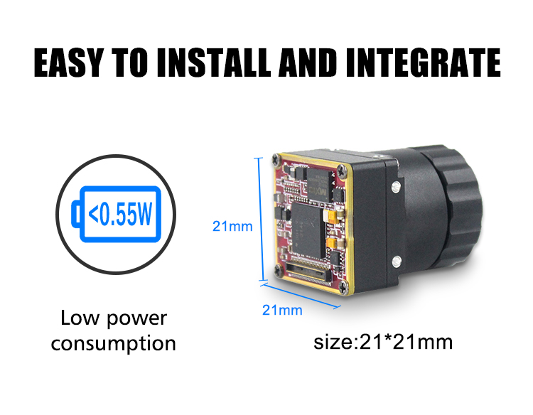
Uncooled LWIR Mini 256*192 Thermal Imaging Camera Module
This micro-bolometer core is built for applications where physical space and payload weight are limited. It features a compact design, low power consumption, and refined image-processing pipelines, making it a suitable choice for mobile search-and-rescue gear, micro industrial sensors, and custom tactical integrations.
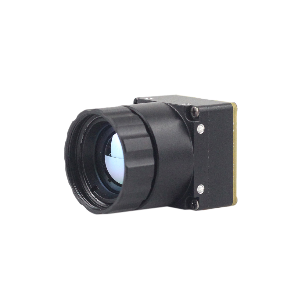
The Mini 256 thermal camera core utilizes high-performance detectors for clear thermal imaging and accurate temperature measurements. The module captures infrared radiation and outputs a uniform, calibrated thermal image. Its low power draw and lightweight design allow it to be easily integrated into handheld devices, inspection tools, and small drone platforms.
View Product Details & Pricing ➔
Uncooled Infrared RJ45 CVBS RTSP IP 640*512 ASIC Thermal Sensor Camera Module
For applications requiring higher resolution, longer range, and integrated network connectivity, this module features a 640×512 pixel array. This higher pixel count provides sharp thermal imagery and accurate remote measurements over long distances.

This premium uncooled module is designed around a high-performance infrared detector, supported by a specialized ASIC video-processing engine. It provides dual analog (CVBS) and digital network outputs, and supports direct RTSP streaming over RJ45 Ethernet. These features make it well-suited for industrial automation, perimeter security, and larger aircraft payloads.
View Product Details & Pricing ➔
Engineering Specification Comparison
| Performance Parameter | Uncooled LWIR Mini 256 Module | Uncooled RJ45/CVBS 640 Module |
|---|---|---|
| Sensing Resolution | 256 × 192 Pixels | 640 × 512 Pixels |
| Pixel Configuration | 12µm Pitch Uncooled Microbolometer | 12µm Pitch Uncooled Microbolometer |
| Spectral Range | 8µm to 14µm (LWIR) | 8µm to 14µm (LWIR) |
| Thermal Sensitivity (NETD) | <50mK at f/1.0, 300K | <40mK at f/1.0, 300K |
| Output Interfaces | SPI, USB Type-C, Custom GPIO options | RJ45 Ethernet, CVBS Analog, RS232/TTL UART |
| Network Protocols | N/A (Local Bus Stream Only) | RTSP, RTP, ONVIF, TCP/IP, UDP, DHCP |
| Onboard Processor | Ultra-Low-Power Base Image Processor | Dedicated ASIC Video Engine with Dynamic AGC/DDE |
| Operating Voltage | 3.3V to 5V DC | 5V to 12V DC |
| Primary Deployment | DIY Goggles, Mini UAV Payloads, Remote Thermography | Industrial Process Automation, Security, Tactical Drones |
For applications requiring specialized high-framerate video cores with intermediate field-of-view arrays, consider reviewing the technical specifications of our Uncooled Mini 384x288 Thermal Camera Module for Drones. This core balances pixel density, sensor mass, and processing overhead for multi-rotor aircraft deployments.
6. Thermal Night Vision Fusion System Architecture
Multi-spectral thermal image fusion combines thermal and visible imaging by overlaying heat signatures from an LWIR sensor onto the high-resolution, structure-rich video stream of a low-light CMOS camera. This combination helps operators maintain situational awareness—allowing them to identify physical objects, structures, and text while simultaneously highlighting hot zones or living targets.
To implement a multi-spectral fusion pipeline, developers can follow these core engineering steps:
⚙️ Aperture Alignment and Parallax Correction: Because the thermal sensor and the visible camera have separate lenses, their optical pathways are offset. This offset creates a parallax error that is especially noticeable at close ranges. To correct this, mount the cameras as close together as possible. In software, map the coordinates of the thermal video onto the visible video coordinates utilizing calculation matrices that account for focal length, scaling, and rotation differences between the two lenses.
⚙️ Edge Separation Filtering: Apply a software filter (such as a Sobel or Canny edge detector) to the visible-light camera frame. This isolating process extracts high-contrast details like fences, walls, steps, and foliage boundaries, stripping away unnecessary color and flat lighting information.
⚙️ Applying Palettes and Heat Thresholds: Map the raw thermal values to a color palette (such as orange or red for hot targets, and deep blue or transparent for cold targets). Using threshold limits, isolate only specific temperature bands. This allows the system to colorize only human body heat or machinery components while ignoring ambient background temperatures.
⚙️ Direct Alpha Blending: Combine the processed thermal and visible streams using an alpha-blending formula. This blends the structural edge detail with the colorized temperature information, producing a final composite video stream that displays both clear physical outlines and accurate thermal hotspots. This processed hybrid video can then be output directly to a head-mounted display or recorded on a central flight storage drive.
7. Mechanical, Electrical, and Optical Integration FAQ
How does a 256x192 thermal module compare to 320x240 for DIY night vision projects?
Can these ultra-compact Chinese thermal cores be easily integrated with Raspberry Pi or microcontrollers?
Is a 256x192 CMOS-sized thermal sensor module sufficient for true tactical night vision?
📚 References & Further Reading
- Industry Standard: Learn about micro-scale thermal arrays and semiconductor layout rules on JM Chip.
- Technical Foundations: Review the solid-state principles of uncooled LWIR detectors on Wikipedia Microbolometer.
- Related Guide: Explore practical steps for setting up sensor pipelines in our Thermal Camera Core Integration Guide.





