








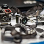
Buy 25mm Electronic Focusing Thermal Camera Module (640x512 VOx, 35mk, H.265/BT.656/CVBS) for UAVs & FPV
2026年7月16日
Guangzhou Purple River MIPI USB Thermal Camera Module: High-Res Embedded IR Solutions
2026年7月17日

# Mini 640 Thermal Camera Module: Night Vision CMOS Analog Video & H.265 Integration Guide
The rapid convergence of drone-based thermography, tactical night vision systems, and edge-computing surveillance has created an urgent demand for lightweight, high-performance thermal imaging components. For hardware architects, defense contractors, and R&D engineers, integrating a thermal core is no longer just about capturing heat signatures; it is a complex engineering challenge involving size, weight, power, and cost (SWaP-C) optimization, multi-sensor synchronization, and low-latency video streaming.
This guide serves as a comprehensive system integration blueprint for the **Mini 640 Thermal Camera Module**. We will examine the core engineering principles of uncooled Long-Wave Infrared (LWIR) detectors, dissect the mechanical and electrical interfaces required to pair a 640×512 thermal core with high-sensitivity CMOS night vision sensors, and evaluate concrete software integration strategies for processing raw video feeds across diverse hardware environments—from analog FPV goggles to edge-AI Single Board Computers (SBCs) like the Raspberry Pi running real-time computer vision frameworks.
Table of Contents
- 👉 1. Technical Fundamentals of Uncooled LWIR Thermal Cores
- 👉 2. Dual-Sensor Fusion: Uncooled LWIR & CMOS Integration
- 👉 3. Digital & Analog Video Interfaces: H.265, MIPI, and CVBS
- 👉 4. Optical Selection & Lens Parameter Optimization
- 👉 5. SWaP-C Optimization for Drone Payloads and Man-Portable Systems
- 👉 6. Showcase & Product Specifications
- 👉 7. Step-by-Step Software Integration & Edge-AI Analytics
- 👉 8. Deep-Dive Integration FAQ
---
1. Technical Fundamentals of Uncooled LWIR Thermal Cores
At the heart of the Mini 640 Thermal Camera Module is an uncooled microbolometer focal plane array (FPA) operating in the Long-Wave Infrared spectrum (typically 8 micrometers to 14 micrometers). Unlike cooled thermal sensors that require bulky, power-hungry cryocoolers to drop sensor temperatures to near 77 Kelvin, uncooled LWIR cores operate at ambient temperatures. This makes them highly suitable for SWaP-constrained applications like tactical wearables and small unmanned aerial vehicles (UAVs).
Here's the deal with uncooled sensors: they make design life infinitely easier when you are tight on space, but you have to understand the underlying sensor physics to squeeze every ounce of performance out of them.
### Microbolometer Architecture: VOx vs. a-Si
Modern uncooled thermal sensors primarily rely on one of two thin-film semiconductor materials: **Vanadium Oxide (VOx)** or **Amorphous Silicon (a-Si)**.
Look, in the shop, we run into this debate all the time. Here is how they stack up:
✅ **VOx (Vanadium Oxide):** This is the gold standard for high-performance thermal imaging. VOx detectors offer a higher Temperature Coefficient of Resistance (TCR). What this means for your design is simple: you get a much lower noise floor and superior thermal sensitivity. This translates directly to a lower Noise Equivalent Temperature Difference (NETD).
✅ **a-Si (Amorphous Silicon):** Silicon-based FPAs provide a highly uniform material structure. This uniformity facilitates pixel-to-pixel consistency and helps mitigate spatial noise patterns over time. The trade-off? You are usually looking at marginally lower raw sensitivity compared to VOx.
The sensing pixels consist of a suspended silicon nitride microbridge structure coated with the active VOx or a-Si thermistor layer. When incident LWIR radiation strikes the pixel, the microbridge absorbs the photons, raising its physical temperature. This temperature shift alters the electrical resistance of the thermistor. A Read-Out Integrated Circuit (ROIC) bonded directly beneath the sensor array applies a bias voltage across the pixel, converting the resistance variation into a measurable analog signal. This signal is then digitized via high-speed on-board Analog-to-Digital Converters (ADCs).
Mini 640×512 Thermal Imaging Core Demo Video
### Resolution, Pixel Pitch, and Spatial Resolution
The spatial resolution and overall image performance of an uncooled thermal core are defined by three primary parameters:
1. **Focal Plane Array Resolution:** An array of 640x512 pixels represents 327,680 individual thermal pixels. This is a dramatic increase in spatial data over lower-resolution 256x192 fields (49,152 pixels). It allows operators to resolve targets at significantly longer physical ranges.
2. **Pixel Pitch:** The center-to-center distance between adjacent detector pixels on the FPA. As semiconductor fabrication has progressed, pixel pitch has shrunk from 25 micrometers down to 17 micrometers, and now down to 12 micrometers. Reducing the pixel pitch lowers the physical footprint of the detector chip, enabling more compact and light lenses while maintaining a wide Field of View (FOV).
3. **Instantaneous Field of View (IFOV):** Measured in milliradians (mrad), IFOV represents the spatial resolution of a single pixel and is calculated using the pixel pitch (d) and the focal length (f) of the lens. The formula is IFOV = d / f. A smaller pixel pitch combined with a larger focal length delivers a narrower IFOV, allowing the optical system to project a single pixel onto a much smaller physical area at long distances. This is a key requirement for military-grade target acquisition and power grid inspection.
### Thermal Sensitivity (NETD) and Spatial Noise Calibration
The thermal sensitivity of an infrared sensor is defined by its Noise Equivalent Temperature Difference (NETD), measured in millikelvins (mK). NETD represents the temperature difference that produces a signal-to-noise ratio (SNR) of unity. A lower NETD indicates a more sensitive camera. Standard commercial systems sit below 50 mK, whereas high-performance grade cores, such as the Mini 640 modules, hit below 35 mK. This allows them to resolve subtle thermal details even in challenging low-contrast conditions like thick fog, pouring rain, or complete darkness.
Uncooled microbolometers suffer from inherent spatial non-uniformity caused by minor variations in pixel-to-pixel resistance, biases, and optical vignetting. This shows up as fixed pattern noise (FPN) across the active image. To counteract this, modules execute a Non-Uniformity Correction (NUC).
⚙️ **The NUC Calibration Pipeline:**
* **Mechanical Shutter Event:** The system periodically closes a mechanical shutter—or uses a shutterless software algorithm—to present a uniform thermal temperature reference to the entire sensor array.
* **Coefficient Calculation:** The module's internal processor recalculates offset and gain correction coefficients for each individual pixel.
* **Pixel Uniformity Remap:** The real-time video processor applies these correction tables on the fly, eliminating fixed pattern noise entirely.
Integrating continuous NUC algorithms is critical for mission-critical installations to maintain clean, artifact-free imagery. For more on tactical deployments of thermal systems under challenging conditions, check out this guide on the best night thermal camera module for DIY projects and tactical applications.
---
2. Dual-Sensor Fusion: Uncooled LWIR & CMOS Integration
While an uncooled LWIR core excels at detecting heat signatures in zero-light environments, it lacks the high-frequency spatial details—such as text, letters, fine structural outlines, and color—provided by visible-light cameras. Dual-sensor fusion merges the strengths of an LWIR sensor with a high-sensitivity, low-light Complementary Metal-Oxide-Semiconductor (CMOS) sensor to produce a single, information-rich video stream.
### Optical Co-Alignment and Parallax Error Calibration
Fusing a thermal sensor and a CMOS sensor requires physical co-alignment. Because the two optical centers are separated by a physical baseline distance, they view the scene from slightly different perspectives, creating parallax error.
To resolve this issue, you need to configure the system using these key steps:
⚙️ **Step 1: Rigid Physical Mounting:** Mount the physical sensors as closely as possible on a rigid, thermally stable housing to prevent mechanical drift under vibration.
⚙️ **Step 2: Homography Matrix Calibration:** Apply software-based parallax correction in real-time. The geometric relationship between the coordinate space of the CMOS sensor and the LWIR sensor is calibrated using a 3x3 homography matrix (H). This transformation accounts for X and Y displacements, rotation, and focal scale differences.
⚙️ **Step 3: Checkerboard Calibration Routine:** Expose the camera assembly to a co-aligned thermal-visible checkerboard target. Corner-detection algorithms run to calculate the exact homography parameters, which are stored in the module's non-volatile memory.
⚙️ **Step 4: Runtime Re-projection:** At runtime, the DSP applies this transformation matrix to re-align the CMOS pixels, ensuring pixel-perfect calibration regardless of the target's distance.
### Pixel-Level Fusion Algorithms
Once aligned, the thermal and visible streams are combined using pixel-level fusion algorithms. The goal is to retain the high-energy spatial details of the CMOS image while using the thermal data to colorize heat signatures:
1. **High-Pass Filtering / Edge Extraction:** The CMOS image is converted to a luminance channel and passed through a spatial high-pass filter (such as a Sobel, Laplacian, or Canny filter) to isolate structural contours and textures.
2. **Color Space Conversion (YCbCr):** The LWIR channel is mapped to a chosen pseudo-color palette (e.g., Ironbow, White Hot, Black Hot).
3. **Luminance and Chroma Overlap:** The extracted high-frequency structural lines from the CMOS sensor are overlaid onto the luminance channel of the thermal image. Concurrently, the color and heat intensity data of the thermal camera are blended into the chrominance channels.
The resulting blended video frame preserves both high-contrast thermal signatures and readable text labels or facial contours. This makes the system ideal for search-and-rescue teams, industrial inspectors, and security forces operating under absolute darkness.
---
3. Digital & Analog Video Interfaces: H.265, MIPI, and CVBS
Different applications demand specific video interfaces. Developers must evaluate the physical layer requirements, protocols, and latency implications of the three primary video signals supported by modern mini 640 modules to balance system performance constraints.
### MIPI CSI-2 (Mobile Industry Processor Interface)
For edge-AI, robotics, and tight embedded processor integration, MIPI CSI-2 is the preferred interface. It is a high-speed, differential serial bus designed for point-to-point connections between image sensors and application processors, such as the NVIDIA Jetson, Raspberry Pi, or NXP i.MX8.
The Mini 640 module transfers uncompressed 14-bit raw radiometric data over two MIPI data lanes, along with a dedicated differential clock lane. This high bit depth provides access to raw thermal ADC counts (radiometric temperature measurements) rather than just an 8-bit visual image. MIPI CSI-2 operates with near-zero latency, as the raw sensor data is DMA-transferred directly into the host processor's memory buffer. Because MIPI relies on high-frequency, low-voltage signaling, the transmission distance is physically constrained. Traces on custom carrier boards must be impedance-matched to 100 ohms (+/- 10%) and must not exceed 15–20 cm in length without specialized active re-driver chips.
### H.265/HEVC and H.264 IP Video Streaming
For network-based security cameras, long-distance drone telemetry links, and remote industrial monitoring, the module's on-board system-on-chip converts raw data into compressed H.265 (High-Efficiency Video Coding) or H.264 streams.
H.265 offers up to a 50% bitrate reduction compared to progress-generation H.264 codecs at equivalent visual quality. This is vital when transmitting high-resolution 640x512 thermal video at 30 frames per second (fps) over cellular links or crowded ISM band telemetry transmitters. The H.265 stream is encapsulated inside standard networking protocols like RTSP (Real-Time Streaming Protocol) or ONVIF (Open Network Video Interface Profile). This allows systems to connect the mini thermal IP core directly into commercial-off-the-shelf Network Video Recorders (NVRs) or common video management systems (VMS). However, compression introduces a latency penalty of 50 to 150 ms due to the processing time required for macroblock analysis, motion estimation, and frame buffering.
### CVBS (Color, Video, Blanking, and Sync) Analog Video
For tactical FPV drones and legacy integration, CVBS remains highly relevant. It transmits composite baseband analog video over a single coaxial cable or differential pair.
Unlike digital pipelines that require packet buffering and decoding steps, CVBS presents a continuous analog signal. It features sub-millisecond propagation latency, making it the preferred standard for high-speed piloting through analog FPV goggles. Operators can configure the analog output of the Mini 640 module for either NTSC (640x480 resolution at 29.97 fps) or PAL (720x576 resolution at 25 fps). However, CVBS is susceptible to RF interference and suffers from signal attenuation over long cables. High-frequency video components can degrade, resulting in a slightly softer image with analog artifacts in electrically noisy environments.
---
4. Optical Selection & Lens Parameter Optimization
An infrared detector's performance is heavily limited by its optical assembly. Because regular optical glass absorbs LWIR wavelengths, thermal lenses are constructed using specialized materials like **Germanium (Ge)**, **Chalcogenide Glass**, or **Silicon (Si)** with specialized anti-reflective coatings. Selecting the optimal optics is critical to match the system's mission profile.
### Optical Transmission Materials
In the shop, we work with these core optical materials:
✅ **Germanium (Ge):** This is the gold standard for high-performance LWIR lens systems. It offers an exceptionally high refractive index (approximately 4.0 in the LWIR band) and low dispersion. It provides high optical transmission efficiency (greater than 90% with anti-reflective coatings) but is relatively heavy and sensitive to thermal variance, which can cause focus shifts (thermal defocus).
✅ **Chalcogenide Glass:** A cost-effective, lighter alternative to Germanium that can be precision molded into complex aspheric shapes. This reduces spherical aberrations while keeping raw production costs low.
✅ **Silicon (Si):** Primarily utilized for short focal length lenses or lightweight, lower-cost configurations. Though more rugged than Germanium, its dispersion characteristics and transmission efficiency in the 8-14 micron band restrict its usage to less critical consumer configurations.
### Aperture (f-number) and Transmission Efficiency
The f-number, or aperture, is the ratio of the lens focal length (f) to the diameter of the entering aperture (D). The mathematical representation is:
$$\text{Aperture } (F) = \frac{\text{Focal Length } (f)}{\text{Diameter of Aperture } (D)}$$
The amount of thermal radiation that reaches the FPA is inversely proportional to the square of the lens's f-number:
$$\text{Radiation Flux} \propto \frac{1}{F^2}$$
A lens with an aperture of F/1.0 captures twice as much infrared radiation as a lens with F/1.4. Selecting an objective lens with a low f-number is crucial to maximizing the effective NETD of the camera sensor. This produces sharp, high-contrast images even in low thermal gradient conditions.
### Lens Focal Length Options and Detection Ranges (DRI)
Designing or procuring a thermal system requires calculating the DRI (Detection, Recognition, Identification) distances based on the Johnson Criteria:
* **Detection:** Is an object present? (requires at least 1.5 pixels on target).
* **Recognition:** What type of object is it? (requires at least 6.0 pixels on target).
* **Identification:** Specific details of the object? (requires at least 12.0 pixels on target).
Below is an optical configuration matrix mapping focal lengths to target Fields of View (FOV) and safe-side 12-micron FPA DRI calculations for a standard human target (1.8 meters x 0.5 meters):
---
5. SWaP-C Optimization for Drone Payloads and Man-Portable Systems
Designing tactical soldier-worn equipment (like monoculars or goggles) or UAV payloads places strict limits on physical parameters. Engineers must manage SWaP-C (Size, Weight, Power, and Cost) to maximize flight times and minimize operator fatigue.
* **Size (Footprint Reduction):** The ultra-compact footprint of **21mm x 21mm** allows the thermal module to fit into tight setups, such as miniature gimbals on DJI-type civilian search drones, tactical helmet-mounted NVG/thermal fusion housings, and compact weapon-mounted sights.
* **Weight (Flight and Combat Optimization):** Standard thermal cameras can weigh over 100 grams, requiring heavy structural mounts. A lightweight mini thermal core (under 15 grams without optics) reduces the mechanical load on gimbal motors. This translates directly to smoother stabilization and extended flight times for battery-dependent quadcopters. For handheld tactical gear, this light weight reduces neck strain during long missions.
* **Power Consumption (Under 1.5W Operational Draw):** The uncooled LWIR core is optimized for dynamic power savings. It runs on a wide input range (typically 3.3V to 5.0V DC) and consumes less than 1.5W of power during steady-state operation. This low power draw limits self-heating, which can otherwise introduce thermal noise and compromise sensor readings over prolonged use.
* **Environmental Survivability (IP54 Enclosure Rating):** Devices intended for wilderness search-and-rescue, tactical operations, or industrial inspections require robust protection against environmental hazards. An IP54-rated ingress protection housing shields the sensitive uncooled microbolometer sensor and internal processing electronics from dust storms and splashing water. This ensures reliable performance in hostile elements. Interested in historical deployments of airborne observation networks under intense environmental pressures? Read more about the remote sensor systems deployed during the landmark October 2007 wildfires in Santa Clara, California.
---
6. Showcase & Product Specifications
To assist system integrators and layout designers in selecting the appropriate core relative to budget and payload targets, this technical registry compiles detailed specifications of high-performance mini modules.
Uncooled LWIR USB Mini 640*512 Thermal Imaging Camera Core Module For Drones Similar To DJI

Mini uncooled infrared thermal imaging module features in sharp and crisp image presentation, compact size and low cost.
Mini-Size of 21mm*21mm, 5/9/13/18/35/50/75/100/150mm, 640*480 resolution optional, stable performance and strong environmental adaptability.
View Product Details & Pricing ➔
* * *
Uncooled LWIR Mini 256*192 Thermal Imaging Camera Module Similar To DJI For Detecting Mines
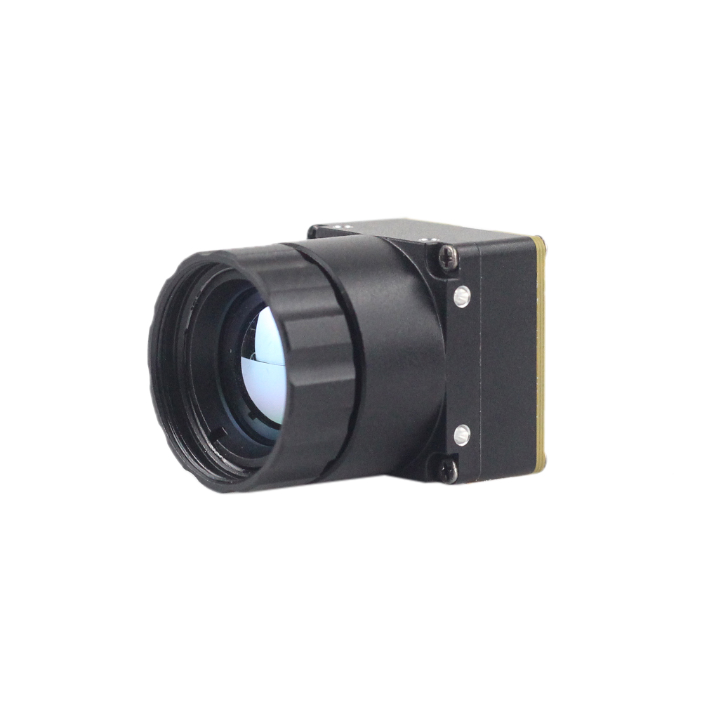
Mini 256 Uncooled LWIR thermal Camera Module adopts high-performance infrared detectors for ultra-clear thermal imaging and accurate temperature measurement. It captures infrared radiation and outputs a uniform thermal image with radiometry.
View Product Details & Pricing ➔
* * *
Comparative Technical Specifications
---
7. Step-by-Step Software Integration & Edge-AI Analytics
Processing raw video from the Mini 640 over USB or MIPI CSI-2 requires a structured software pipeline. The code sample below demonstrates how to interface with the camera using OpenCV in Python on a Linux-based SBC (such as a Raspberry Pi). This program captures raw video frames, runs threshold-based hotspot detection, and overlays tracking indicators in real-time.
```python
#!/usr/bin/env python3
"""
Developer Integration Blueprint: Real-Time Dynamic Target Tracking
Component Target Hardware: Mini 640 Uncooled LWIR Thermal Imaging Core Module
"""
import cv2
import numpy as np
import sys
def initialize_thermal_pipeline(device_id=0):
"""
Establishes communication with the Mini 640 over standard USB UVC or MIPI Virtual driver interface.
"""
# Open capture stream (0 is typically the default system camera link)
cap = cv2.VideoCapture(device_id)
# Configure capture frame attributes for natural 640x512 resolution configuration
cap.set(cv2.CAP_PROP_FRAME_WIDTH, 640)
cap.set(cv2.CAP_PROP_FRAME_HEIGHT, 512)
if not cap.isOpened():
print(f"Error: Unable to connect to thermal module on device index {device_id}")
sys.exit(1)
return cap
def run_analytical_process_loop(cap):
print("Initiating thermal tracking segment. Press 'q' to safely terminate loop.")
while True:
ret, frame = cap.read()
if not ret:
print("Error: Empty frame buffer received from sensor.")
break
# Convert frame to grayscale if received as color, for calculations
if len(frame.shape) == 3:
gray_frame = cv2.cvtColor(frame, cv2.COLOR_BGR2GRAY)
else:
gray_frame = frame
# Apply a Gaussian blur to mitigate fixed pattern noise (FPN) artifacts and high-frequency outliers
blurred = cv2.GaussianBlur(gray_frame, (5, 5), 0)
# Locate the absolute brightest (hottest) pixel in the thermal frame
min_val, max_val, min_loc, max_loc = cv2.minMaxLoc(blurred)
# Dynamically segment hotspots using thresholding
# Pixels with values above 90% of the maximum value are isolated
threshold_value = max_val * 0.90
_, thresholded_img = cv2.threshold(blurred, threshold_value, 255, cv2.THRESH_BINARY)
# Retrieve structural contours from the segmented hotspot regions
contours, _ = cv2.findContours(thresholded_img, cv2.RETR_EXTERNAL, cv2.CHAIN_APPROX_SIMPLE)
# Draw a custom pseudo-color map for display (Jet or Ironbow approximation)
colored_frame = cv2.applyColorMap(gray_frame, cv2.COLORMAP_JET)
# Iterate over located contours and draw a bounding box around large hotspots
for contour in contours:
# Ignore tiny signal spikes (e.g., area < 20 pixels) to avoid false positives
if cv2.contourArea(contour) < 20:
continue
# Calculate bounding rectangle metrics for valid thermal targets
x, y, w, h = cv2.boundingRect(contour)
# Draw green bounding box around target
cv2.rectangle(colored_frame, (x, y), (x + w, y + h), (0, 255, 0), 2)
# Label the hotspot location with its localized value
cv2.putText(colored_frame, f"HOTSPOT VAL: {int(max_val)}", (x, max(y - 10, 15)),
cv2.FONT_HERSHEY_SIMPLEX, 0.5, (0, 255, 255), 2)
# Point target marker at the exact hottest peak coordinate
cv2.drawMarker(colored_frame, max_loc, (0, 0, 255), cv2.MARKER_CROSS, 20, 2)
# Render the final processing visualization to the active viewport
cv2.imshow("Mini 640 Real-Time Thermal Analytics Overlay", colored_frame)
# Handle keyboard interrupts for clean application termination
if cv2.waitKey(1) & 0xFF == ord('q'):
break
# Release pipeline resources upon loop exit
cap.release()
cv2.destroyAllWindows()
if __name__ == "__main__":
thermal_cap = initialize_thermal_pipeline(0)
run_analytical_process_loop(thermal_cap)
```

8. Deep-Dive Integration FAQ
Can I stream real-time, high-resolution 640x512 thermal video to a Raspberry Pi or Arduino?
How do you achieve night vision fusion with an analog thermal module and a CMOS sensor?
What makes this mini 640 module suitable for custom DIY monoculars or drone payloads compared to closed commercial systems?
---
📚 References & Further Reading
- Industry Standard: Real-time computer vision development via the open-source OpenCV Library.
- Related Guide: Explore our design resources for building lightweight, tactical thermal gear in our Tactical Night Thermal Camera DIY Integration Guide.
- Sitemap & Product Selection: Browse our complete uncooled core lineup through the Thermal-Image Shop Portal.





