AI Thermal Camera Selection Guide: High-Precision Modules & OEM Integration
2026年8月6日
OEM Thermal Core Selection & Upgrade Guide: High-Resolution LWIR Modules for Integrators
2026年8月7日

Commercial Infrared Camera Guide: AI Thermal Imaging vs Near Infrared Solutions
If you're an automation architect, drone engineer, or system integrator, you've likely noticed the industrial imaging world shifting underneath our feet. Legacy visual sensors just aren't cutting it anymore. Everyone is pushing toward multi-spectral thermal optics, but making the jump isn't as simple as swapping out a camera core. Selecting the right infrared camera module means getting your hands dirty with wavelength physics, microbolometer sensor architecture, dynamic range compression, and tight interface standards. Look, whether you're building autonomous drone payloads, running high-voltage substation diagnostics, or setting up zero-light perimeter security, choosing between active Near-Infrared (NIR) illumination and passive Long-Wave Infrared (LWIR) thermal microbolometers will make or break your deployment when bad atmospheric weather hits.
Here's the deal: this guide is written from the bench. We are going deep into OEM thermal camera modules, edge AI algorithmic integration, dynamic palette processing, and how to tame size, weight, power, and cost (SWaP-C) constraints. By looking closely at sensor physics and real-world specs, you'll walk away with the practical framework needed to select, wire up, and deploy high-resolution thermal imaging cores into tough industrial settings.
Table of Contents
- 👉 1. Infrared Spectrum Fundamentals: Physics & Wavelength Bands
- 👉 2. NIR vs. LWIR Sensor Architecture: Mechanical & Optical Divergence
- 👉 3. Microbolometer Engineering: VOx, Pixel Pitch, and NETD Physics
- 👉 4. Edge AI Compute, Radiometric Analytics, and Sensor Fusion
- 👉 5. Drone Payload SWaP-C Optimization & Physical Interconnects
- 👉 6. Commercial Infrared Camera Hardware Lineup
- 👉 7. Step-by-Step OEM Integration Protocol
- 👉 8. Industrial Frequently Asked Questions (FAQ)
1. Infrared Spectrum Fundamentals: Physics & Wavelength Bands
The non-visible electromagnetic spectrum sits right between visible light (0.38 µm to 0.75 µm) and microwave frequencies (>1000 µm). In electro-optical design, we split the infrared domain into four distinct sub-bands based on atmospheric transmission windows and photon behavior. Picking the wrong band for your operational environment is the easiest way to blow an engineering budget, so let's break down how these bands behave on the factory floor and out in the field.
The Near-Infrared (NIR) spectrum spans 0.75 µm to 1.1 µm. Photons here act almost identically to visible light and pass right through off-the-shelf optical glass elements. Standard silicon photodetectors pick up NIR light without complaining. But here is the catch: NIR imaging relies entirely on reflected radiation from an ambient source or active illuminators like an 850 nm or 940 nm LED array. It won't tell you a single thing about thermal heat emitted by objects sitting at room temperature.
Moving down the line, the Short-Wave Infrared (SWIR) band covers 1.1 µm to 3.0 µm. Working with SWIR means stepping up to specialized substrates like Indium Gallium Arsenide (InGaAs). SWIR light cuts right through atmospheric haze, water vapor, and thick smoke, while still letting you see through standard glass windows. But just like NIR, SWIR depends on reflected photons rather than direct heat signatures.
Then we have Mid-Wave Infrared (MWIR), running from 3.0 µm to 5.0 µm. MWIR is built to spot intense heat signatures—think hot jet exhausts, missile plumes, and high-temperature furnace combustion. However, MWIR sensors rely on quantum detectors (InSb or MCT) that require active cryogenic cooling down around 77 Kelvin using onboard Stirling pumps. That adds huge physical size, heavy power draw, and ongoing mechanical maintenance headaches that rule it out for lightweight gear.
Finally, the Long-Wave Infrared (LWIR) spectrum covers 8.0 µm to 14.0 µm. This is the sweet spot for uncooled commercial thermography. Everything above absolute zero emits heat in this band, strictly following Planck's Law and Wien's Displacement Law (λmax · T = 2898 µm·K). For everyday targets near ambient terrestrial temperatures (~300 Kelvin), radiant emission peaks square inside that 8 µm to 14 µm window. An LWIR microbolometer core captures true passive heat profiles in total darkness without needing active IR spotlights or heavy coolers.

If you're putting together physical housing specs or picking optical elements for tight sensor payloads, check out our in-depth high-resolution thermal camera module integration guide.
2. NIR vs. LWIR Sensor Architecture: Mechanical & Optical Divergence
When you sit down to design an optical platform, your absolute first choice is deciding whether you're capturing reflected illuminator light (NIR) or direct thermal radiation (LWIR). The engineering path splits immediately across lens materials, silicon substrates, and real-world weather capabilities.
Standard visual and NIR cameras use silicon-based CMOS or CCD sensors. Incoming photons strike the silicon lattice, knocking valence electrons across the 1.11 eV silicon bandgap into the conduction band to build a readable electric charge. Standard optical glass (flint and crown glass) transmits NIR photons without an issue. But LWIR photons carry way less quantum energy (~0.1 eV)—nowhere near enough to jump a standard silicon bandgap. Worse yet, conventional silica glass absorbs LWIR energy completely. Try placing a standard camera lens over an LWIR sensor, and it acts like a solid brick wall.
To capture LWIR radiation, an infrared camera relies on custom optics machined from single-crystal Germanium (Ge), Silicon (Si), or Chalcogenide glass formulations. Germanium has a massive refractive index (n ≈ 4.0 in the LWIR spectrum), which lets us design compact, fast lenses with tight optical aberrations. But untreated Germanium reflects over 30% of incident heat energy per surface interface. That means we have to vacuum-coat these lenses with durable Anti-Reflective (AR) hard-carbon coatings to max out optical transmission and withstand nasty real-world dust and grit.
In practice, NIR cameras give you high spatial detail, sharp text, and recognizable textures when supplied with infrared illuminators. But turn on a fog machine, throw up a cloud of dust, or introduce heavy smoke, and NIR gets blinded fast by backscatter. LWIR microbolometers slice right through smoke, fog, and pitch-black nights because they read actual surface thermal delta between the target and the background.
3. Microbolometer Engineering: VOx, Pixel Pitch, and NETD Physics
Inside every modern uncooled LWIR infrared camera core lies a MEMS focal plane array called a microbolometer. Instead of counting individual photons, a microbolometer absorbs thermal radiation directly. Each pixel is a tiny micro-machined bridge suspended above a silicon Readout Integrated Circuit (ROIC) by thin, thermally isolated legs. To dig deeper into the MEMS fabrication process behind these sensors, check out this reference on Wikipedia Microbolometer technology.
As thermal radiation strikes the pixel's absorbing membrane, its temperature climbs, shifting its electrical resistance. The underlying ROIC measures this shift across every pixel in the grid, outputting raw uncompressed thermal datasets (usually 14-bit or 16-bit counts). The two dominant thin-film materials used on these microbolometer bridges are Vanadium Oxide (VOx) and Amorphous Silicon (a-Si).
Vanadium Oxide (VOx) remains the gold standard across industrial and tactical thermal setups. VOx offers a solid Temperature Coefficient of Resistance (TCR) between 2% and 3% per degree Celsius. In plain English, that high TCR translates directly to better thermal sensitivity, low intrinsic 1/f electronic noise, and bulletproof calibration across wide temperature sweeps. Amorphous Silicon (a-Si) is easier to run through standard CMOS fab lines, bringing down manufacturing costs, but a-Si films suffer from lower TCR values and higher intrinsic noise floors.
Pixel pitch—the center-to-center distance between neighboring pixels—governs overall optical size and resolution density. The industry has pushed hard down from legacy 25 µm and 17 µm designs into tight 12 µm arrays. Shrinking pixel pitch shrinks the overall sensor footprint. That means you can run smaller, lighter Germanium optics with shorter focal lengths while keeping the exact same spatial resolution and Field of View (FOV). That weight reduction is everything for aerial payloads.
We measure thermal sensitivity using Noise Equivalent Temperature Difference (NETD), expressed in millikelvins (mK). NETD is the smallest temperature step a sensor can distinguish above its own internal noise floor. Mathematically, it works out to:
NETD = Vn / (ΔV / ΔT)
Where Vn is system noise voltage, and ΔV / ΔT represents thermal voltage responsivity. Lower mK numbers mean a much cleaner thermal picture:
- 📌 NETD < 50 mK: Industrial baseline grade. Great for spotting hot electrical breakers, HVAC leaks, and basic vehicle detection.
- ⚡ NETD < 30 mK: High-sensitivity grade. Resolves tiny thermal gradients across building insulation, subtle PCB trace loads, fugitive gas leaks, and long-range search-and-rescue targets.
For bench notes and real-world image evaluation of low-NETD cores packed into compact housings, see our miniature 640x512 thermal imaging camera performance breakdown.
4. Edge AI Compute, Radiometric Analytics, and Sensor Fusion
Modern thermal camera design isn't just about outputting an analog composite video signal anymore. Modern OEM thermal camera cores carry embedded System-on-Chip (SoC) architectures and specialized Neural Processing Units (NPUs) directly on the readout board. This setup lets you run real-time target tracking, full radiometric calculations, and sensor fusion right at the edge without lugging around a power-hungry host PC.
Raw 14-bit thermal feeds need a lot of cleaning up before an operator or an object detection model can make sense of them. Here is the core processing sequence on the board:
- ⚙️ Non-Uniformity Correction (NUC): Normalizes gain and offset variations across every pixel in the MEMS array. A mechanical shutter or a shutterless algorithm regularly resets the baseline to eliminate ugly fixed-pattern noise artifacts.
- ⚙️ 3D Dynamic Noise Reduction (3DNR): Applies spatial and temporal filtering to suppress frame thermal jitter without smearing high-speed moving targets.
- ⚙️ Digital Detail Enhancement (DDE): High-pass spatial filtering algorithms that pull out high-frequency structural edges, small anomalies, and fine background textures in low-contrast environments.
Because the human eye can't distinguish thousands of shades of gray in a 14-bit stream, dynamic Look-Up Tables (LUTs) map raw intensity data into readable pseudo-color palettes:
- 🎨 White-Hot / Black-Hot: High-contrast grayscale modes. The top choice for tactical target spotting, flight navigation, and security perimeters.
- 🎨 Ironbow / Rainbow: Maps thermal gradients across high-visibility spectrum colors (blues to intense yellows). Critical for industrial predictive maintenance and tracing high-resistance busbars.
- 🎨 Custom Radiometric Isotherms: Highlights specific user-defined temperature windows in real-time (like turning anything over 80°C neon red) for automated alert flags.
Onboard NPUs run lightweight Convolutional Neural Networks (CNNs) straight on raw thermal frames. While visual RGB models get thrown off by nighttime shadows or glare, thermal AI models track human and machinery heat signatures in total darkness. Dual-spectrum platforms take this further by blending structural edges from a high-resolution visible CMOS sensor with the thermal heat overlay, giving you crisp contextual text and physical lines overlaid with exact radiometric heat maps.
5. Drone Payload SWaP-C Optimization & Physical Interconnects
Plugging thermal camera cores into small drone frames or mobile inspection robots forces you to manage tight Size, Weight, Power, and Cost (SWaP-C) budgets. Every extra gram strips away flight time, while power draw impacts your battery performance and thermal isolation options.
Electromagnetic interference (EMI) is a huge headache in compact drone frames. The intense high-frequency electrical noise coming off motor Electronic Speed Controllers (ESCs) and wireless telemetry transmitters easily bleeds into sensitive microbolometer ROIC boards, causing nasty visual banding and destroying your effective NETD. You've got to run proper electrical shielding, clean ground planes, and high-grade interconnects to keep the signal clean.
When selecting micro-pitch board-to-board connectors engineered to handle tough mechanical vibration and shock in drone payloads, check out industrial solutions from Molex.
Picking the right physical connection dictates both your cabling layout and processing latency:
- 🔌 MIPI CSI-2 (Mobile Industry Processor Interface): The absolute standard for embedded vision. MIPI CSI-2 gives you an uncompressed, zero-latency direct line into edge AI processors (like NVIDIA Jetson or Rockchip modules) over short ribbon cables.
- 🔌 USB 3.0 Type-C: Great plug-and-play connectivity providing power and digital video over a single flexible cable. Perfect for ground crawlers and rapid prototyping rigs.
- 🔌 Ethernet RTSP / ONVIF: Standard network protocol for fixed security networks, streaming real-time compressed H.264/H.265 video over long wire runs.
To see how these compact modules perform during live system bench testing, watch our full thermal camera operational video demonstration.
6. Commercial Infrared Camera Hardware Lineup
Matching the right infrared camera core to your project means balancing resolution density, optical setups, interface standards, and thermal sensitivity. Below are two proven industrial-grade cores engineered specifically for aerial payloads, fixed surveillance systems, and predictive maintenance rigs.
High Resolution Uncooled Infrared 1280*1024 Thermal Imaging LWIR Camera
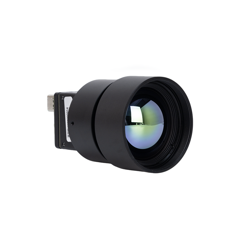
Engineered for high-definition thermography, this megapixel LWIR thermal core packages a massive 1280x1024 resolution focal plane array with a precision 25mm Germanium hard-carbon coated lens. Designed for OEM integrators who need wide coverage and ultra-fine target resolution without missing micro-degree temperature spikes.
- ✅ Resolution Profile: HD 1280 × 1024 Megapixel Grid
- ✅ Optical Configuration: 25mm Fixed Germanium Hard-Carbon Coated Lens
- ✅ Detector Material: High-Sensitivity Uncooled LWIR Microbolometer
- ✅ Target Systems: Perimeter Defense, Substation Monitoring, Industrial Inspection
Uncooled Infrared MIPI 640 384 256 9mm Thermal Imaging Camera Module For Drones

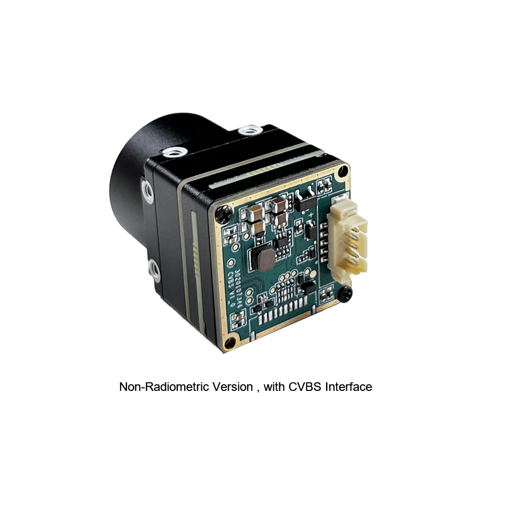
The Mini2 drone module is purpose-built for light aerial payloads. Available in flexible array resolutions (640x512, 384x288, or 256x192) and paired with an ultralight 9mm Germanium lens, it hooks directly into host platforms via a low-latency MIPI CSI-2 interface. Low power draw, light weight, and zero-latency output make it a flight-ready solution.
- ✅ Resolution Options: 640×512, 384×288, or 256×192 Array Configurations
- ✅ Optics & Weight: 9mm Focal Length, Ultra-Lightweight Chassis
- ✅ System Interface: Low-Latency Digital MIPI CSI-2 Embedded Connector
- ✅ Target Systems: Tactical Drones, Search & Rescue (SAR), Solar Panel Inspection
Hardware Specification Matrix
| Parameter / Specification | HD 1280x1024 25mm LWIR Camera | Mini2 MIPI Drone Camera Module |
|---|---|---|
| Spectral Band | 8 – 14 µm (LWIR) | 8 – 14 µm (LWIR) |
| Native Sensor Resolution | 1280 × 1024 Pixels (HD Class) | 640×512 / 384×288 / 256×192 Options |
| Focal Length & Lens Assembly | 25mm Fixed Germanium Optics | 9mm Ultra-Compact Germanium Lens |
| Primary Data Output | Digital Parallel / Custom High-Bandwidth | Direct Embedded MIPI CSI-2 Connector |
| SWaP Optimization Profile | Fixed Surveillance / Industrial Chassis | Ultra-Light Payload Footprint for Drones |
| On-Board Signal Processing | Hardware NUC, DDE, 3DNR, Palette LUTs | Embedded NUC, Crisp Edge Enhancement |
7. Step-by-Step OEM Integration Protocol
Getting a thermal infrared camera module mounted and talking cleanly to your host processor requires a disciplined engineering approach. Here is the step-by-step protocol we follow on the bench to prevent hardware ground loops, noisy images, and thermal drift:
Step 1: Mechanical Mounting & Thermal Isolation
Microbolometer performance relies on thermal equilibrium. If you bolt a thermal core straight onto a hot power supply or next to vibrating motor mounts, heat will transfer through the frame and drift the sensor calibration, ruining your NETD sensitivity.
- ⚙️ Mount the thermal core using anodized aluminum or thermally non-conductive nylon standoffs.
- ⚙️ Design structural dissipation channels in the housing so heat from high-draw compute chips drains away from the camera microbolometer housing.
- ⚙️ For drone mounts, insert tuned silicone damping grommets to kill off high-frequency mechanical vibration from motors and props.
Step 2: High-Speed Interface Cabling & Electrical Shielding
MIPI CSI-2 and parallel video lines are prone to electromagnetic interference (EMI). High switching noise from motor speed controllers will wreak havoc on your video feed if you aren't careful.
- ⚙️ Run custom shielded flex-rigid PCB trace cables with matched differential pair impedance (100-ohm differential).
- ⚙️ Keep your high-speed ribbon cable lengths under 100 mm to stop signal degradation and EMI noise pickup.
- ⚙️ Separate your camera signals physically from power distribution boards (PDB) and ESC cabling.
Step 3: Software SDK & Signal Control Pipeline Initialization
With hardware locked down, talk to the sensor board registers over I2C or UART using the SDK:
- ⚙️ Initialize camera control registers and lock down frame rates (e.g., 30 Hz for tracking systems, or 9 Hz for export-compliant hardware).
- ⚙️ Set up video data streaming formats. Choose raw 14-bit or 16-bit Y16 modes when doing true temperature math, or 8-bit YUV/RGB palette mapped streams for human operators.
- ⚙️ Configure mechanical shutter intervals for Non-Uniformity Correction (NUC) or program automated software triggers to refresh calibration during temperature shifts.
Step 4: Radiometric Calibration & Scene Parameter Adjustment
Converting raw digital readings into true temperature readings (°C or °F) means tuning parameters inside your software pipeline:
- ⚙️ Target Emissivity (ε): Set the target material coefficient (e.g., polished metal ε ≈ 0.05, oxidized copper ε ≈ 0.65, matte black paint ε ≈ 0.98).
- ⚙️ Atmospheric Distance & Humidity: Feed target distance and humidity settings into the pipeline to account for atmospheric attenuation across long ranges.
- ⚙️ Reflected Background Temp: Program ambient environmental parameters to filter out heat reflections bouncing off smooth surfaces.
8. Industrial Frequently Asked Questions (FAQ)
What is the exact difference between Near Infrared (NIR) photography and Thermal (LWIR) imaging?
Can a standard camera record infrared light, or do I need a dedicated infrared camera?
Are there 'color' thermal infrared cameras available for OEM integration?
How do pixel pitch and optical focal length affect thermal target detection distances (DRI ranges)?
Why is Flat Field Correction (FFC) / Non-Uniformity Correction (NUC) mandatory in LWIR microbolometers?
📚 References & Further Reading
- Industry Standard Microbolometer Reference: Wikipedia Microbolometer Architecture & MEMS Overview
- Interconnect Technical Standards: Molex Precision Board-to-Board Payload Connectors
- High-Resolution Integration Guide: High Resolution Thermal Camera Module Integration Engineering Protocol
- Miniature Module Performance Report: Mini 640 Thermal Camera Module Performance Evaluation
- Video Hardware Demonstration: Thermal Camera Operational Video Demonstration