LWIR Micro Thermal Camera Module: The Ultimate Integration Guide for Drones and Edge AI Solutions
2026年6月10日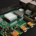
Best Raspberry Pi Thermal Camera Module for High-Res Edge AI & Linux Streaming
2026年6月11日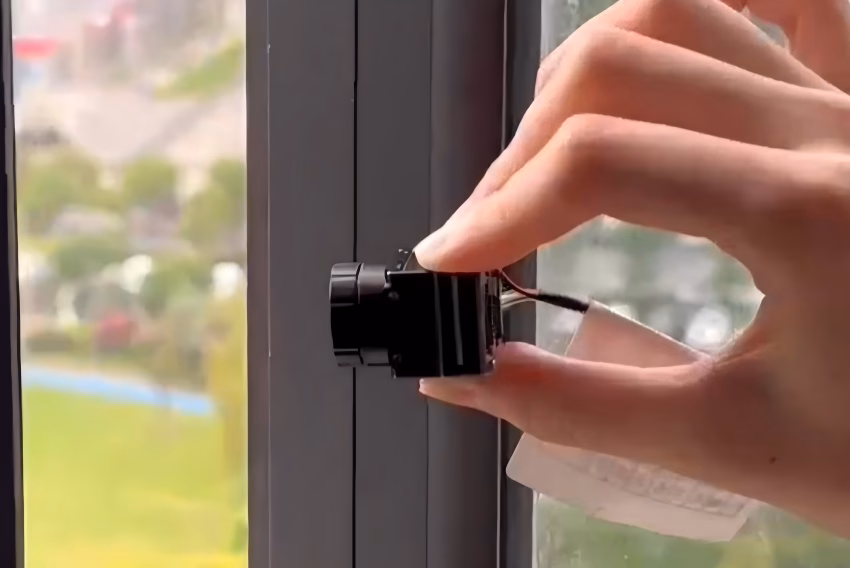
Best Micro Thermal Camera Module Guide: High-Res Integration for Drones, Raspberry Pi & Edge AI
In the industrial automation world, aerial surveillance, and edge computing, thermal imaging is no longer a luxury. It has officially transitioned from a high-cost, specialized tool to an absolute necessity for modern embedded systems. At the center of this shift is the micro thermal camera module. By shrinking uncooled Long-Wave Infrared (LWIR) sensors down to miniature footprints—often measuring a mere 21mm × 21mm—hardware developers can now run high-resolution thermal vision systems in weight-sensitive, power-constrained environments. These modules strip away the physical bulk of old-school thermal cameras while delivering thermal sensitivity under 40mK or 50mK NETD at spatial resolutions up to 640×512 pixels.
Here's the deal: if you are a technical team building unmanned aerial vehicles (UAVs), rugged edge computing hardware, or specialized medical diagnostics, picking and integrating a micro thermal core is a game of balancing SWaP-C (Size, Weight, Power, and Cost). This guide is designed to serve as your hands-on engineering blueprint. We will look past the marketing sheets and dive deep into actual sensor mechanics, interface choices like USB, CVBS, and RJ45 RTSP, integration pathways for single-board computers like the Raspberry Pi or NVIDIA Jetson, and compare state-of-the-art uncooled ASIC modules optimized for modern AI and drone platforms.
Table of Contents
- 👉 1. Technical Foundations of Micro Thermal Camera Modules
- 👉 2. Drone Payload Integration: Designing for Strict SWaP-C Budgets
- 👉 3. SBC & Edge AI Interfaces: From Hardware to SDK Processing
- 👉 4. Deep-Product Analysis: Mini 640 Series Modules
- 👉 5. Optomechanical Selection & Multi-Sensor Fusion Strategies
- 👉 6. Deep Technical FAQ (Integration Troubleshooting)
1. Technical Foundations of Micro Thermal Camera Modules
To integrate a micro-thermal system successfully, you need to look past simple resolution numbers and understand the underlying physics of uncooled Long-Wave Infrared (LWIR) sensing. The signal capture pipeline begins when incident infrared light passes through optical lenses, impacts the sensor substrate, and undergoes signal conditioning before exiting as a digital stream.
Here is how the signal moves through the hardware:
- ⚙️ Optical Focusing: Ambient thermal radiation (spanning the 8 to 14 μm spectrum) passes through a specialized germanium lens. Germanium is highly transmissive to infrared light, unlike optical glass, which acts as a solid wall to LWIR.
- ⚙️ Infrared Absorption: This focused thermal light is absorbed by the uncooled Vanadium Oxide (VOx) microbolometer array.
- ⚙️ Resistance Change: The temperature changes the electrical resistance of the microbolometer pixels.
- ⚙️ ROIC Signal Processing: The Read-Out Integrated Circuit (ROIC) measures and amplifies these small electrical changes.
- ⚙️ Digital Cleanup: The raw values are passed to an Application-Specific Integrated Circuit (ASIC) where non-uniformity corrections (NUC) and dead-pixel filtering are applied.
- ⚙️ Interface Streaming: The corrected, low-noise thermal video is output over digital or analog interfaces.
VOx Microbolometers and Spectral Responsivity (8–14 μm)
Unlike cooled thermal systems that require heavy, power-hungry cryogenic coolers, modern micro thermal camera modules rely on an uncooled Vanadium Oxide (VOx) microbolometer. VOx materials feature an exceptionally high Temperature Coefficient of Resistance (TCR). In simple terms, their electrical resistance changes dramatically and predictably when exposed to infrared radiation.
The sensor array is engineered to absorb electromagnetic radiation in the 8 to 14 micron (μm) spectral window. This range aligns with the atmospheric transmission window where earth-bound objects emit most of their thermal energy (typically from -20°C to +150°C and higher). Working within this band means you can capture clean thermal signatures without relying on ambient sunlight or active IR illuminators.
When infrared photons hit the micro-machined bridge structure of an individual pixel, the bridge heats up relative to the underlying substrate. This thermal insulation is achieved using silicon-nitride support arms suspended above the silicon readout circuit. The resistance change of this suspended VOx bridge is measured frame-by-frame by the ROIC bonded beneath the microbolometer structure. The ROIC converts this physical analog resistance variance into raw digital units (known as digital counts or ADUs) which represent localized temperature trends.
Pixel Pitch Evolution: 17μm vs. 12μm Technology
Pixel pitch—the center-to-center distance between adjacent detector pixels on the focal plane array—directly dictates your camera's size-to-resolution efficiency. In the physical layout of your system, transitioning from the historical 17μm standard to modern 12μm technology has major downstream design benefits:
- ✅ Refined Footprint (SWaP-C): Shrinking the pixel pitch to 12μm reduces the physical size of the sensor die. This smaller footprint allows for highly compact enclosures, making 640×512 resolution systems possible on miniature platforms.
- ✅ Lighter Optomechanics: Because the sensor die is smaller, you can use lenses with shorter focal lengths to achieve the same target Field of View (FOV). This helps reduce the size, weight, and cost of downstream Germanium optics.
- ✅ Preserved Thermal Sensitivity: While smaller pixel surfaces collect fewer photons, advanced VOx thin-film deposition and ultra-low-noise ROICs allow these 12μm sensors to maintain an equivalent or superior Noise Equivalent Temperature Difference (typically NETD ≤ 40mK or 50mK), keeping image contrasts sharp.
Image Optimization: Non-Uniformity Correction (NUC) and Image Processing
Because microbolometers are highly sensitive to thermal drift from their own housing and circuitry, raw thermal video output is naturally prone to noise and spatial patterns. To produce a clean, high-contrast thermal image, the micro core's internal processing engine runs direct digital signal processing (DSP) pipelines:
During Non-Uniformity Correction (NUC), the micro thermal core periodically closes a physical internal mechanical shutter (or uses algorithmic, shutterless predictive profiling) to measure a uniform temperature zone. It then calculates offset correction matrices to equalize the output of all array pixels, compensating for spatial variance. Next, Bad Pixel Replacement (BPR) routines identify dead or non-responsive pixels in real-time and interpolate their values from adjacent functional pixels. Finally, 3D Noise Reduction (3DNR) and Contrast Enhancement algorithms apply temporal and spatial filters to smooth out random white noise, while Adaptive Dynamic Range Compression (DRC) translates raw 14-bit thermal data into clean, contrast-optimized 8-bit visual streams (such as white-hot, black-hot, or false-color palettes).

2. Drone Payload Integration: Designing for Strict SWaP-C Budgets
Integrating a thermal sensor onto an unmanned aerial vehicle (UAV)—especially tight sub-250-gram systems—demands rigid adherence to Space, Weight, Power, and Cost (SWaP-C) optimization. Hardware design choices directly impact physical balance, stabilization, and imaging quality.
Power delivery requires clean, low-noise DC lines. Typically, the UAV main power bus routes raw battery voltage to an active LC Pi-Filter network to strip away high-frequency motor switching noise before feeding the micro-thermal module. High-speed, high-flex micro-coaxial or flexible flat cabling then transfers the raw digital data through active brushless gimbal rings to the host flight controller or radio transmitter, keeping rotational resistance to an absolute minimum.
Sub-250g Drone Engineering and Payload Budgets
In current global aviation regulatory frameworks, the 250-gram ceiling is a strict threshold for recreational and commercial UAV deployment. For developers building light inspection drones, every fractional gram determines flight duration. A standard micro thermal camera module with a 21mm × 21mm cross-section weighs less than 15 to 20 grams, making it highly compatible with these compact designs. This extremely low weight minimizes the drone's structural payload, leaving more overhead for payload power systems and propulsion battery capacities.
In the shop, we aim to locate the thermal core as close as possible to the UAV's physical center of gravity (CoG). This minimizes the work required by the flight controller and electronic speed controllers (ESCs) to keep the aircraft stable, preserving battery life and extending operational flight times. Minimizing rotational inertia about the Pitch, Roll, and Yaw axes ensures that aerial stabilization is prompt and predictable.
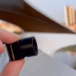
In addition to planning optical and physical layouts, engineers should study complete aerial integration setups to optimize their designs. Reading a comprehensive drone thermal imaging pod guide helps ground your custom core configuration within real industry practices. For a practical look at how these tiny thermal cores perform under dynamic flight conditions, review this operational video of thermal imaging camera module with drone.
Electromagnetic Interference (EMI) Mitigation
Micro drones feature high-power brushless motor drives, high-frequency ESC switching, and high-gain RF transmitters (like 2.4GHz / 5.8GHz video links and telemetry systems) packed into a highly confined space. Uncooled thermal sensors operate on exceptionally micro-scale change measurements, making them vulnerable to electromagnetic interference (EMI).
- ⚙️ Enclosure Shielding: Use lightweight, copper-clad polyimide tape or miniature CNC-machined aluminum enclosures around the camera module's driver board. Ground the enclosure directly to the system's central zero-volt (0V) reference. This blocks radiative noise emitted from near-proximity RF antennas.
- ⚙️ Power Line Filtering: Switch-mode power regulators on drones can inject high-frequency switching noise into the thermal core's delicate analog-to-digital converters (ADCs), manifesting as horizontal routing lines across the thermal image. Use dedicated LDOs (Low-Dropout Regulators) or active LC Pi-filter networks on the supply input lines of the camera core to maintain constant DC values.
- ⚙️ Differential Routing: Route high-speed digital lines (e.g., USB 2.0 or RJ45 Ethernet) through continuous high-flex micro-coaxial or shielded flat-printed circuits (FPC) rather than loose single-conductor wires. Ensure differential data pairs run parallel with tight geometric matching to maximize common-mode rejection.
Optical Selections & Gimbal Mechanical Design
Because thermal modules must be stabilized to generate usable data, they are typically integrated into 2-axis or 3-axis active brushless gimbals. Selecting the physical lens directly dictates gimbal balance requirements:
| Lens Focal Length | Optical Weight Impact | Dynamic Balance Challenge | Ideal Base Application |
|---|---|---|---|
| 5mm – 13mm | Ultra-Lightweight (<5g) | Minimal rotational inertia; easy to balance on micro brushless motors. | Close-up drone flight, agricultural mapping, indoor search and rescue (SAR). |
| 19mm – 35mm | Mid-Range Weight (10–25g) | Elevates mechanical torque demands on roll/tilt gimbal axes. | Solar panel inspection, utility power-line monitoring from medium altitudes. |
| 50mm – 150mm | High Weight (50–180g) | Significant cantilever mass. Requires high-torque motors and active counterbalance brackets. | High-altitude surveillance, border patrol, long-range object discovery. |
3. SBC & Edge AI Interfaces: From Hardware to SDK Processing
Connecting a micro thermal camera core to a Single-Board Computer (SBC)—such as a Raspberry Pi or NVIDIA Jetson developer kit—requires choosing the right physical interfaces and software frameworks.
The processing architecture spans from physical components to high-level framework wrappers. At the bottom layer, the micro thermal camera captures thermal data using uncooled LWIR sensor structures and on-board ASIC units. The connection proceeds depending on the physical model: Option A uses a USB Video Class (USB-UVC) connection directly connected to a Raspberry Pi or similar host, instantiating a Linux V4L2 device node under system resources. Option B processes data via an RJ45 Ethernet link, relying on embedded network stacks to deliver compressed streams over RTSP. Finally, the developer processes frames inside an OpenCV processing loop, integrating machine learning pipelines to parse temperature trends or locate moving targets.
SBC Architecture Compatibility: UVC, SPI, and Network Video
When interfacing with an SBC, developers typically run into three major protocol choices:
- SPI (Serial Peripheral Interface): Typically used on low-power, entry-level microcontrollers. While useful for ultra-budget micro-sensors, raw SPI transfers consume considerable CPU resources on devices like the Raspberry Pi because the processor must manually reconstruct frame buffers. SPI is generally restricted to low frame rates (under 9Hz) and low resolutions.
- USB Video Class (UVC) via USB 2.0: This is the most popular choice for embedded developers. High-end micro thermal camera modules behave exactly like standard plug-and-play webcams. The Linux operating system populates them as `/dev/videoX` devices, natively handled by drivers like V4L2 (Video4Linux2). This approach allows low-latency, 25Hz/30Hz full-resolution streaming with minimal CPU overhead.
- ASIC Network Video (RJ45/RTSP): For physical installations isolated from the computer host, RJ45 modules convert thermal raw data inside dedicated on-board ASICs into compressed H.264/H.265 video profiles. These engines serve standard network RTSP (Real-Time Streaming Protocol) feeds, offloading video compression tasks entirely from the host computer to preserve internal processing capacities.
Edge AI Processing Pipeline: OpenCV with NVIDIA Jetson
Applying machine learning models—such as YOLOv8 or SSD-Mobilenet—to thermal imaging is highly common in automated fire monitoring, border defense, and industrial predictive maintenance. Thermal imagery is single-channel data, though it is usually translated into 3-channel RGB space for standard AI models during inference pipeline steps.
To build a high-efficiency processing pipe on an NVIDIA Jetson, deploy C++ or Python code using OpenCV interacting with GStreamer and NVIDIA's TensorRT libraries. This prevents memory leaks and ensures hardware-accelerated video decoding:
import cv2
import numpy as np

# Initialize the UVC Video stream from the USB micro thermal core
# (Typically outputs a 640x512 standard YUYV stream)
cap = cv2.VideoCapture(0)
cap.set(cv2.CAP_PROP_FRAME_WIDTH, 640)
cap.set(cv2.CAP_PROP_FRAME_HEIGHT, 512)

if not cap.isOpened():
    print("Error: Could not access the micro thermal camera.")
    exit()

while True:
    ret, frame = cap.read()
    if not ret:
        break

    # Convert standard YUYV frame to grayscale representation
    gray_thermal = cv2.cvtColor(frame, cv2.COLOR_BGR2GRAY)

    # Apply a high-contrast False Color mapping for human operators
    color_mapped = cv2.applyColorMap(gray_thermal, cv2.COLORMAP_JET)

    # --- AI Inference Hook ---
    # input_tensor = preprocess(color_mapped)
    # detections = jetson_tensorrt_engine.run(input_tensor)
    # draw_bounding_boxes(frame, detections)

    cv2.imshow('Micro Thermal Core Feed', color_mapped)

    if cv2.waitKey(1) & 0xFF == ord('q'):
        break

cap.release()
cv2.destroyAllWindows()
Networked Thermal Video: RTSP and ONVIF Protocols
For industrial installations, remote processing gateways often poll video from thermal sensors over local networks using RTSP and ONVIF. Using an ASIC-powered module with network integration allows you to run high-efficiency, multi-drop, long-distance network configurations. You configure the network stream once via integrated web interfaces or standard SDK setups, and then distribute the feed to any standard network video recorder (NVR) or software management engine using an rtsp://ip_address/stream1 target, keeping installation wiring clean and manageable.
4. Deep-Product Analysis: Mini 640 Series Modules
To provide clear engineering references, let's analyze two market-proven uncooled LWIR micro thermal modules designed for aerial integration and system-level products.
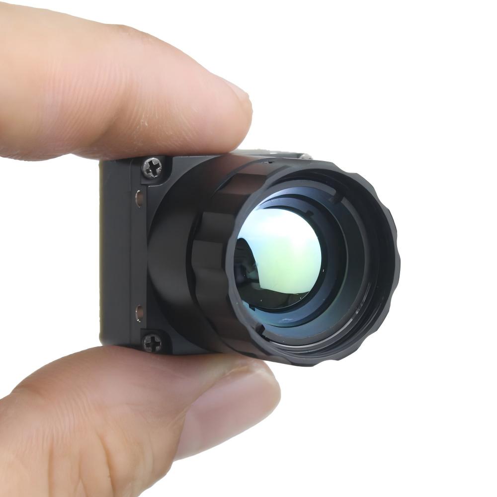
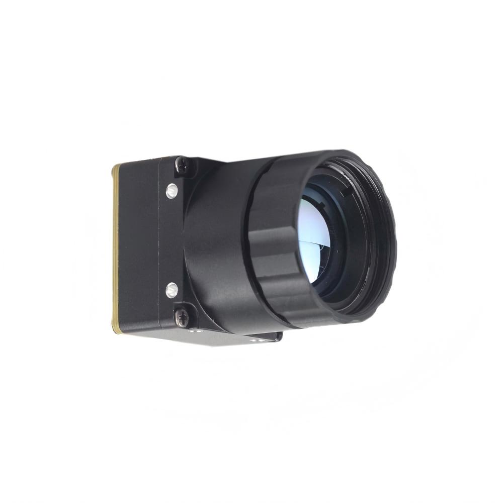
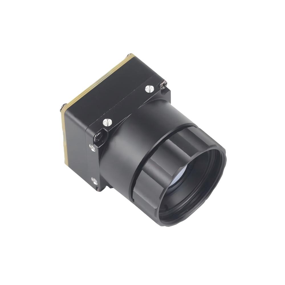
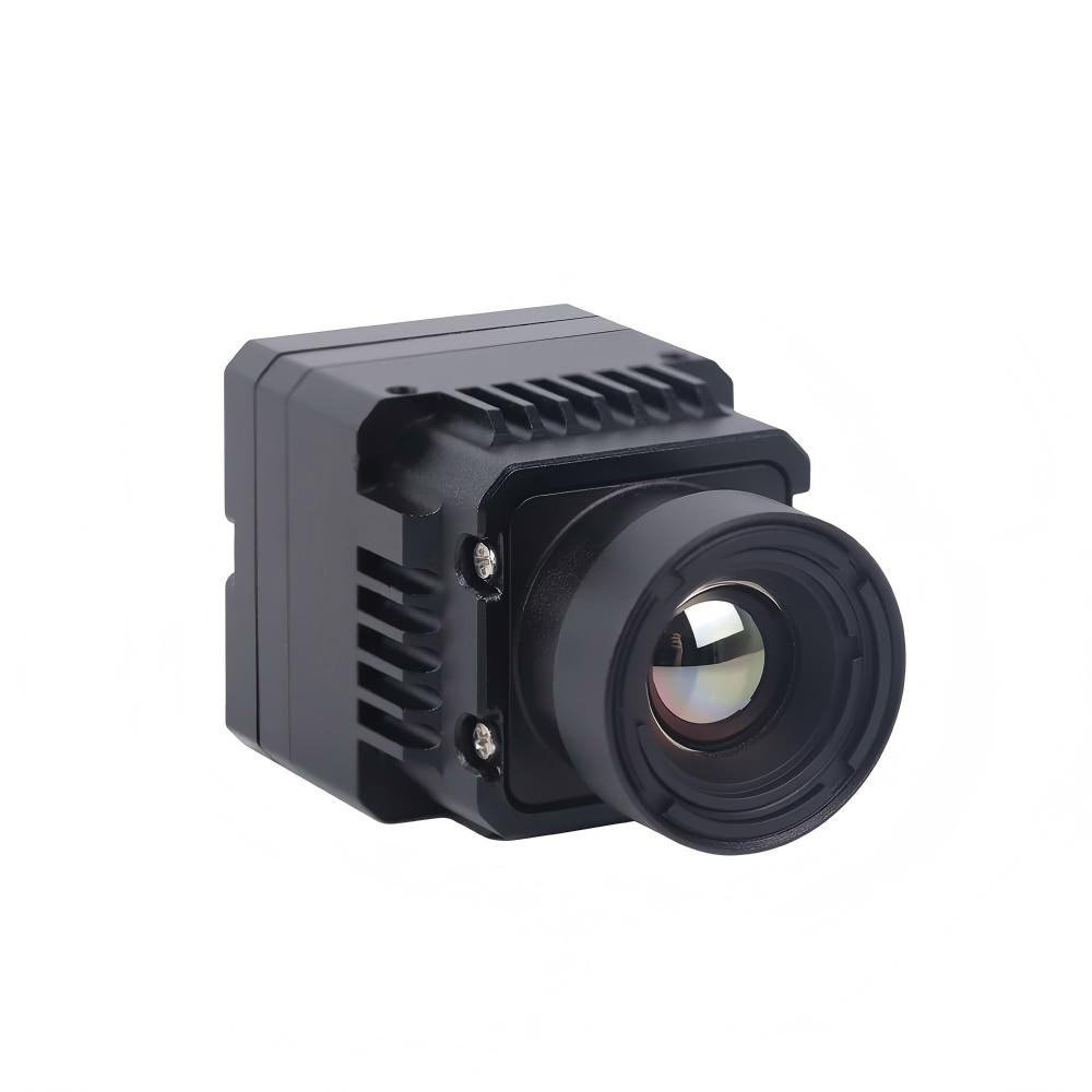
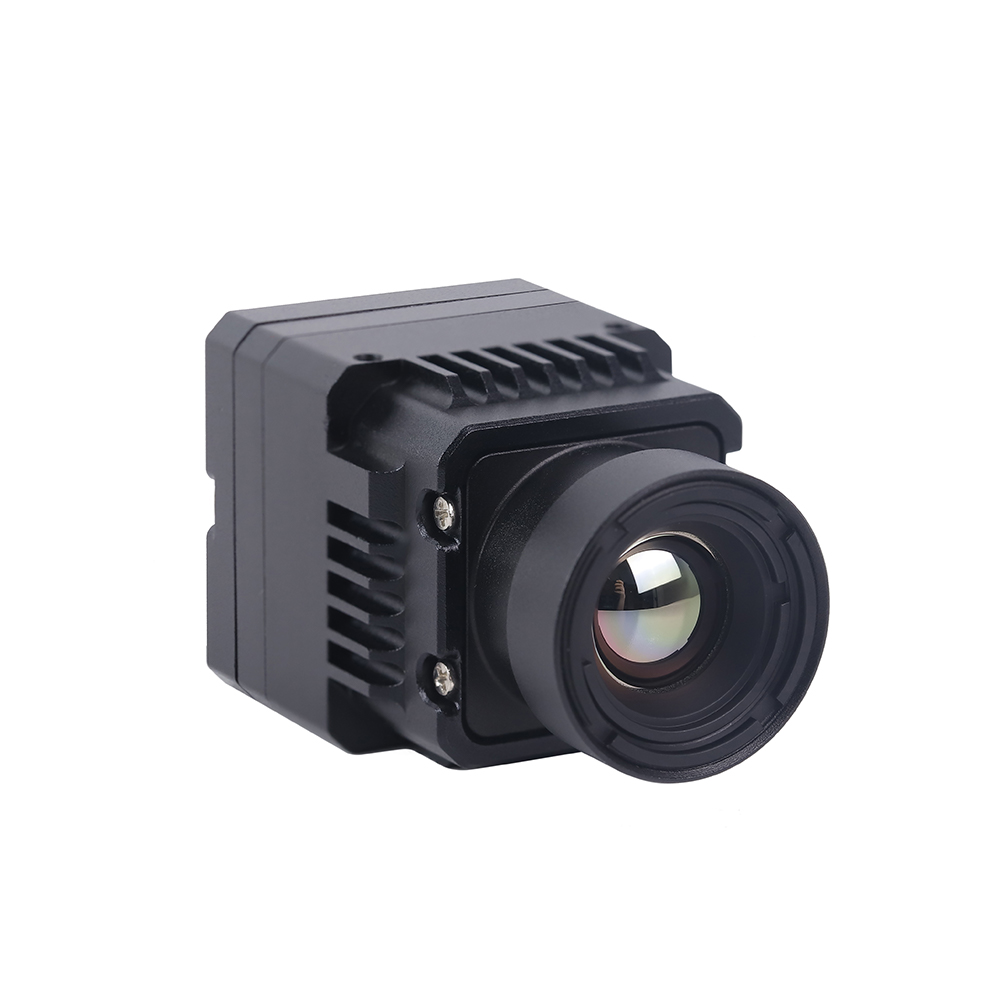
Uncooled LWIR USB Mini 640*512 Thermal Imaging Camera Core Module For Drones Similar To DJI
This ultra-compact VOx microbolometer module is designed for custom drone gimbals and ultra-lightweight integrations. It uses standard USB connectivity to reduce complex integration cycles to zero. It features sharp, crisp image presentation, compact sizing, and extreme cost-efficiency for industrial production tasks.

The core supports exceptional mechanical flexibility. Despite physical dimensions of just 21mm × 21mm, it is compatible with a wide choice of lenses, ranging from wider field-of-view lenses to telephoto germanium blocks. Integrated temperature measurement arrays make the core highly reliable across sweeping temperature envelopes.
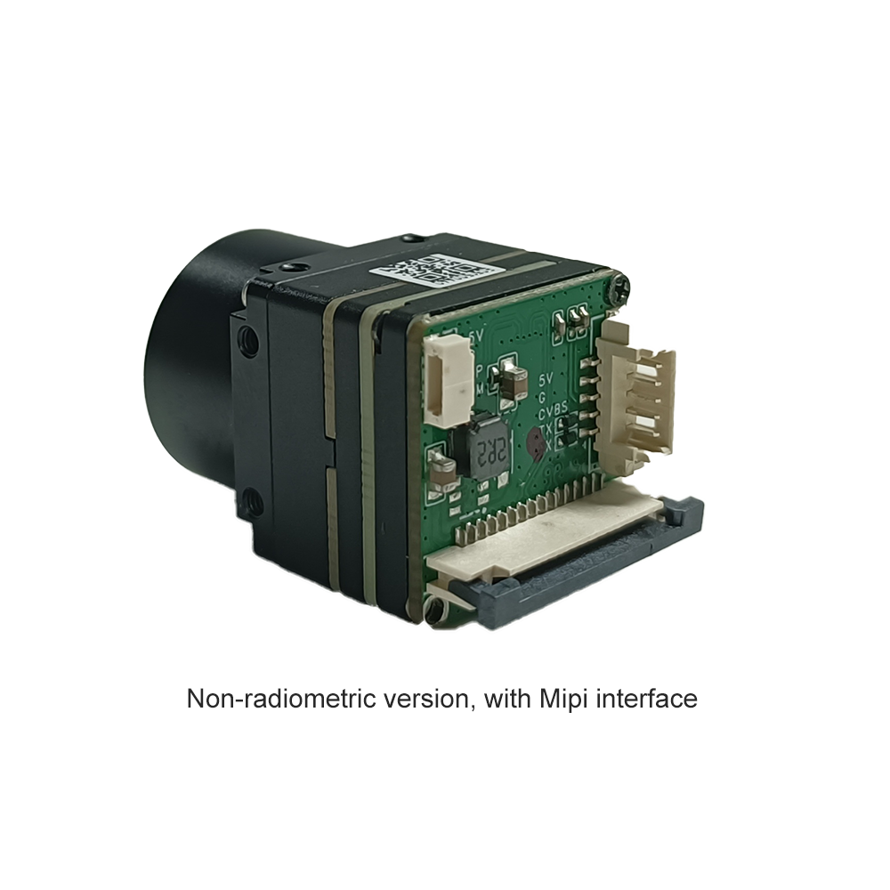
Uncooled Infrared RJ45 CVBS RTSP IP 640*512 Thermal Sensor Camera Module
For projects demanding independent, networked processing without needing a direct host USB interface, this uncooled ASIC configuration integrates network-ready hardware directly onto the core stack. It delivers low latency, low power consumption, and reliable IP video directly from the back of the module.
Engineered for professional industrial nodes and fixed aerial pods, this unit embeds a high-speed ASIC processing layer. By managing network streaming parameters on-board, this module removes processing demands from your central computational cluster.
Technical Specification Matrix
To help hardware developers select the appropriate interface for their design, the table below provides a side-by-side comparison of these two high-resolution uncooled micro thermal devices.
| Parameter / Feature | USB Mini 640*512 Thermal Module | RJ45 CVBS RTSP ASIC Thermal Module |
|---|---|---|
| Detector Technology | Uncooled VOx Microbolometer | Uncooled VOx Microbolometer |
| Native Resolution | 640×512 pixels (640×480 optional) | 640×512 pixels |
| Pixel Pitch | 12μm | 12μm |
| Spectral Range | 8 – 14 μm | 8 – 14 μm |
| NETD (Sensitivity) | ≤50mK (High-sensitivity customized options) | ≤50mK |
| Physical Dimensions | 21mm × 21mm (excluding lens assembly) | Miniature Stacked Footprint |
| Optical Options | Wide range of lenses: 5mm, 9mm, 13mm, 18mm, 35mm, 50mm, 75mm, 100mm, 150mm | Interchangeable fixed focus / customized manual optics |
| Primary Video Interface | USB 2.0 / USB-UVC | RJ45 (Ethernet) & CVBS (Analog) |
| Streaming Protocols | Direct Kernel frame output (14-bit raw, YUYV) | RTSP, IP Streaming, ONVIF |
| Primary Applications | DJI-class drone payloads, robotics, direct SBC/Raspberry Pi developer kits | Remote security installations, Edge AI processors, industrial network nodes |
5. Optomechanical Selection & Multi-Sensor Fusion Strategies
Selecting the matching focal length and optomechanics is critical to optimizing spatial resolution (the ability to resolve small details at distance). This parameter is defined by the sensor's Instantaneous Field of View (iFOV).
Mathematically, the Instantaneous Field of View represents the angular coverage of a single pixel in the focal plane array. The value is calculated using the following formula:
iFOV = d / f
Where d represents the sensor pixel pitch size (e.g., 12μm) and f represents the lens focal length (e.g., 19mm). Applying this math illustrates why decreasing pixel size or increasing optical focal length reduces individual pixel angular envelopes, permitting tighter detail identification at longer range limits.
Lens Math: Matching Focal Length (5mm to 150mm) to FOV
Thermal lenses must be crafted from high-grade Germanium or Chalcogenide glasses. Because uncooled VOx modules cannot look through standard silicate optics, choosing the correct focal length determines your primary physical field limits:
With a narrow focal length like 5mm, the optical system provides a very wide field of view, making it ideal for close-up monitoring or obstacle avoidance systems. Moving to midrange lengths like 35mm creates a tighter, more balanced field of view, which is standard for inspection hardware deployed on medium-altitude UAVs. For long-range identification or border patrol, a long physical Germanium telephoto setup, such as 150mm, narrows the field of view dramatically to focus on distant targets.
- ✅ Wide FOV (5mm to 13mm): Delivers a broad diagonal field of view (often >50°). This configuration is ideal for situational awareness close to the camera, indoor ambient mapping, agricultural canopy studies, and general collision-avoidance setups where wide spatial coverage is more critical than long-range detail.
- ✅ Medium FOV (19mm to 35mm): A balanced approach (20° to 45° FOV) suitable for substation inspection nodes and standard drone flights between 150 and 300 feet AGL (Above Ground Level), providing clear spatial details of power connections.
- ✅ Telephoto/Narrow FOV (50mm to 150mm): Extremely narrow spatial views (<10°). Due to the high weight of Germanium optics (frequently exceeding 100g to 200g), these are best paired with station-locked, heavy-duty PTZ units or specialized drone configurations. They allow engineers to resolve small hotspots on power lines or identify personnel from long distances.
Thermal Sensor Fusion
To overcome the fact that thermal sensors do not capture structural textures or alphabetic details (such as hazard labels or signs), developers frequently deploy Multi-Sensor Fusion pipelines. This digital approach overlays visual and thermal video feeds to combine the benefits of both sensor types.
A visible-light camera (such as a standard CMOS module) captures high-resolution spatial details and raw colors. In parallel, the micro thermal camera captures uncooled VOx temperature matrices. These dual inputs are routed into a homography mapping process. By applying rotation, scale, and translation offset vectors, the software aligns the coordinate structures of both datasets. Finally, an alpha-blending algorithm overlays the edge contrast details from the visible spectrum onto the color-mapped thermal distribution.
By mounting a visible-light camera parallel to the micro-thermal module, you can align their coordinates through software calibration (homography). The visual camera's high-frequency edges are extracted using an edge-detection filter like Sobel or Canny. These edges are then superimposed as an alpha-blended layer over the low-resolution color-mapped thermal image. This technique produces a high-fidelity display where physical outlines remain sharp, and temperature metrics are mapped to their corresponding structures.
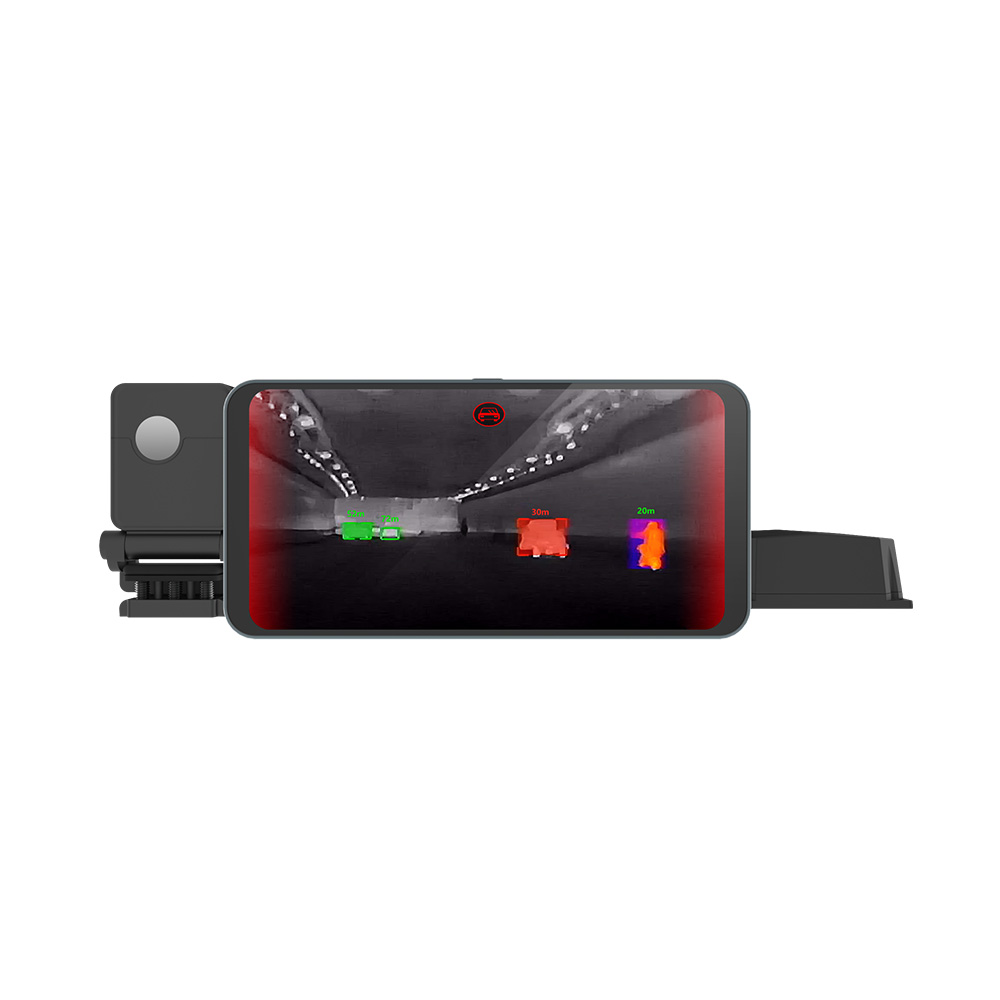
In mobile vehicle integrations, such multi-sensor pipelines are invaluable. Adding a specialized vehicle-mounted thermal camera to the vehicle body alongside visual sensors provides drivers and ADAS algorithms with clear spatial guidance and high-contrast thermal signatures, even in dense fog, heavy rain, or pitch-black operational conditions.

6. Deep Technical FAQ (Integration Troubleshooting)
Q1: How do I stream real-time, high-resolution thermal video to a Raspberry Pi or other SBCs?
Q2: What is the optimal micro thermal module for weight-sensitive applications like under-250g drones?
Q3: Can these micro thermal modules be integrated with Edge AI for custom detection tasks?
📚 References & Further Reading
- Industry Standard: Learn more about computer vision algorithms at the OpenCV Association, and explore embedded machine learning processing hardware frameworks on the official NVIDIA Jetson Platform.
- Related Guide: Read our comprehensive drone thermal imaging pod guide to discover how micro cores are configured for aerial systems design, or explore our rugged vehicle-mounted thermal camera module options.
