CMOS Sensor Technology Guide: Industrial Applications, Vision Systems & Thermal AI Integration
2026年8月17日
Digital Thermal Camera Cores vs Analog: Next-Gen OEM AI Solutions Guide
2026年8月18日

Analog Thermal Camera Modules: High-Precision CVBS & AI Thermal Cores for Industrial Integration
In high-stakes industrial automation, unmanned aerial systems (UAS), field robotics, and defense telemetry, you need visual feedback that doesn't stutter or choke. While modern digital streaming protocols like RTSP over Ethernet, USB Video Class (UVC), and direct MIPI-CSI2 dominate compute-heavy embedded systems, analog thermal camera modules remain the undisputed workhorse for deterministic, zero-latency video pipelines. Outputting clean Composite Video Baseband Signals (CVBS/NTSC/PAL), an analog thermal core bridges long-wave infrared (LWIR) sensor physics directly to continuous, uncompressed analog video lines over long coaxial runs, RF transmitters, and slip rings. This completely bypasses the operating system overhead, compression artifacts, frame buffering, and packet-drop dropouts that plague digital networking stacks.
Here's the deal: modern electro-optical design no longer forces you to choose between bulletproof analog reliability and modern edge compute. Next-generation thermal camera cores run hybrid architectures. We are talking high-resolution Vanadium Oxide (VOx) microbolometer arrays—up to 640×512 resolution at a tight 12μm pixel pitch—paired with dedicated hardware Digital Signal Processors (DSPs). These cores pump out an analog CVBS feed directly to a pilot's field monitor or analog wireless link, while simultaneously pushing uncompressed digital frames (via MIPI-CSI2 or USB) into an edge AI accelerator for real-time computer vision, radiometric thermal tracking, and multi-spectral sensor fusion.
This technical guide breaks down the underlying physics, interface tradeoffs, optical design parameters, PCB-level electrical engineering practices, and real-world integration blueprints required to get industrial-grade analog thermal imaging modules running in demanding field environments.

Table of Contents
- 👉 1. Understanding Analog Thermal Video: Physics, Signal Processing, and CVBS Architecture
- 👉 2. Analog vs. Digital Thermal Interfaces: Latency, Transmission, and Hardware Overhead
- 👉 3. Core Engineering Specifications: Sensor Pitch, NETD, and Optics
- 👉 4. Industrial Product Comparison: MD Series & Mini LWIR Cores
- 👉 5. Electrical & Hardware Integration Playbook: Power, Impedance, and Multi-Bus Bridging
- 👉 6. High-Reliability Industrial and Aerial Application Profiles
- 👉 7. Frequently Asked Questions (FAQ)
1. Understanding Analog Thermal Video: Physics, Signal Processing, and CVBS Architecture
Thermal imaging operates by capturing electromagnetic radiation across the Long-Wave Infrared (LWIR) band, typically between 8μm and 14μm. This domain is governed by Planck’s Radiation Law and the Stefan-Boltzmann Law ($E = \epsilon \sigma T^4$), where any object above absolute zero emits radiation proportional to its emissivity and the fourth power of its absolute temperature. Converting these subtle photon variations into a standard composite video signal requires a tightly managed electro-optical signal path.
The signal chain starts at the front element. Incident LWIR radiation passes through an anti-reflective coated Germanium lens assembly and hits the Focal Plane Array (FPA). In high-performance cores, this array is built from uncooled Vanadium Oxide (VOx) microbolometers. As detailed in standard engineering literature on thermal imaging and thermography, each pixel consists of a microscopic bridge structure suspended over a silicon substrate. When infrared photons strike the bridge, its temperature rises, altering the material's electrical resistance based on its Temperature Coefficient of Resistance (TCR).
Directly beneath the microbolometer matrix, the Readout Integrated Circuit (ROIC) applies an ultra-stable bias voltage, reading the tiny resistance variations row-by-row and column-by-column through capacitive transimpedance amplifiers. These analog signals are immediately converted into raw digital values using high-speed 14-bit or 16-bit Analog-to-Digital Converters (ADCs). Processing raw bolometer data in the digital domain is critical because raw thermal sensors suffer from inherent pixel-to-pixel variations that would otherwise ruin the image.
Inside the module's DSP or FPGA, the raw 14-bit stream passes through a specialized real-time image processing pipeline:
- ⚙️ Non-Uniformity Correction (NUC): Normalizes pixel response variations and cancels thermal drift using factory gain tables combined with mechanical shutter or shutterless calibration updates.
- ⚙️ Defective Pixel Concealment (DPC): Detects unresponsive or noisy pixels on the fly and replaces them with clean interpolated values calculated from adjacent pixels.
- ⚙️ Digital Detail Enhancement (DDE): Applies high-pass spatial filters to pull out fine surface textures and mechanical edges without boosting background sensor noise.
- ⚙️ Dynamic Range Compression (DRC) & Adaptive AGC: Compresses the massive 14-bit dynamic thermal range down into a clean 8-bit scale (256 shades) mapped to target color palettes like White Hot, Black Hot, Ironbow, or Rainbow.
Once the digital frame is fully processed in the DSP line buffers, it reaches the onboard Video Digital-to-Analog Converter (Video DAC). This DAC rebuilds the digital pixel stream into a continuous Composite Video Baseband Signal (CVBS) conforming to standard NTSC or PAL broadcast specifications. It inserts standard horizontal blanking intervals, color burst references (3.58 MHz for NTSC, 4.43 MHz for PAL), active video lines, and vertical sync pulses. An internal operational amplifier drives this composite waveform at 1.0 V peak-to-peak ($1.0 V_{p-p}$) into a matched $75\,\Omega$ load.
2. Analog vs. Digital Thermal Interfaces: Latency, Transmission, and Hardware Overhead
When you are architecting an electro-optical payload for a high-speed drone, robotic arm, or perimeter camera, picking the right video transport protocol is critical. The engineering trade-offs between analog CVBS and modern digital formats (MIPI CSI-2, USB UVC, Ethernet IP) come down to deterministic timing, maximum cable length, physical wiring constraints, and host compute load.
| Architectural Parameter | Analog Composite (CVBS / NTSC / PAL) | Digital MIPI CSI-2 | Digital USB UVC (USB 2.0/3.0) | Network IP (RTSP / GigE Vision) |
|---|---|---|---|---|
| End-to-End Latency | < 1 ms (Zero-latency hardware DAC output) | < 5 ms (Direct SoC register DMA capture) | 30 ms – 100 ms (OS driver stack dependent) | 80 ms – 250 ms (H.264/H.265 compression buffering) |
| Maximum Transmission Distance | Up to 100m+ over standard $75\,\Omega$ coaxial cable | < 15–30 cm (Requires active SerDes chips) | < 3–5 meters without active repeaters | Up to 100m (Cat6 Copper) / Kilometers (Fiber) |
| Cabling & Interconnect Media | 2-wire unbalanced (Coaxial center core + shield GND) | 15–30 pin FPC/FFC high-density ribbon cable | 4-wire shielded twisted pair (VBUS, D-, D+, GND) | 8-wire twisted pair Ethernet (RJ45 or rugged M12) |
| Host Processing Overhead | Zero (Connects directly to CRT/LCD, VTX, or scaler) | High (Demands dedicated hardware ISP / GPU DMA) | Moderate (Kernel UVC stack and decoding threads) | High (Network stack + hardware H.264/H.265 decoder) |
| Slip-Ring & Gimbal Integration | Exceptional (Standard low-cost analog slip rings) | Extremely poor (Severe differential clock/data skew) | Poor (Friction contact micro-disconnects crash USB bus) | Moderate (Requires specialized Gigabit slip rings) |
| Electromagnetic Immunity | High (Resistant to EMI with double-shielded coax) | Low (High susceptibility to EMI/RFI radiation) | Moderate (Susceptible to ground loops and power surges) | High (Galvanic isolation on magnetics) |
Look, the major engineering advantage of analog CVBS is timing determinism. In high-speed UAV piloting, target tracking turrets, and tight closed-loop control systems, latency will make or break your design. Digital video pipelines introduce latency at every single step: sensor readout serialization, frame buffering, video compression (H.264/H.265), packet packaging, network switch hops, decoding threads, and OS display compositing. That easily piles up 60 to 250 milliseconds of total display lag. In dynamic flight operations, 100 milliseconds of lag at 20 m/s means your aircraft is two full meters ahead of what you see on the screen.
Analog CVBS video completely bypasses frame buffers and video encoders. As each horizontal scanline is rendered by the internal DSP, the Video DAC turns it into an analog voltage and pushes it out across the wire in real time, giving you true sub-millisecond pipeline latency. When you pair this with a standard 5.8 GHz analog video transmitter (VTX), the operator gets unbroken visual feedback without packet loss, frozen frames, or digital macroblocking. You can see this setup in action in our video guide of thermal imaging camera modules with drones.
3. Core Engineering Specifications: Sensor Pitch, NETD, and Optics
Specifying an analog thermal core requires analyzing the key electro-optical metrics that govern image resolution, thermal sensitivity, lens sizing, and target range performance.
1. Sensor Pixel Pitch: The Shift from 17μm to 12μm
Pixel pitch is the physical center-to-center spacing between neighboring detector elements on the microbolometer die. Older LWIR systems were built on 17μm or 25μm processes. Modern industrial camera cores use 12μm Vanadium Oxide (VOx) processes. Migrating to 12μm yields significant benefits for Size, Weight, Power, and Cost (SWaP-C):
- ✅ Shorter Focal Length Requirements: To match the Instantaneous Field of View (IFOV) of a 17μm sensor, a 12μm sensor needs an optical focal length roughly 30% shorter. This lets you shrink the front Germanium element, drastically reducing module weight and overall packaging volume.
- ✅ Higher Die Packing Density: A 12μm pitch allows a full 640×512 array to occupy the physical footprint previously required for a 384×288 array, making ultra-compact formats (like 21 mm × 21 mm) possible without sacrificing resolution.
2. Noise Equivalent Temperature Difference (NETD)
Noise Equivalent Temperature Difference (NETD) defines thermal sensitivity. It represents the smallest temperature change between a target and its surroundings that generates a signal equal to internal sensor noise (SNR = 1). NETD is measured in millikelvins (mK):
$\text{NETD} \le 40\,\text{mK} \quad (\text{tested at } f/1.0, \, T_{\text{ambient}} = 300\,\text{K})$
A module rated at $\le 40\,\text{mK}$ easily detects temperature variations as small as $0.04^\circ\text{C}$. In predictive maintenance and continuous condition monitoring, high thermal sensitivity lets you catch subtle thermal anomalies—like high-resistance contacts in power switchgear, early bearing wear, or insulation degradation—well before equipment fails.
3. Optical Train Engineering and Johnson's DORI Criteria
Standard optical glass is completely opaque to infrared radiation between 8μm and 14μm. Thermal imaging optics must be fabricated from specialized infrared materials, primarily monocrystalline Germanium (Ge) or engineered Chalcogenide glass. These optical elements receive Diamond-Like Carbon (DLC) or High-Durability Anti-Reflective (HD-AR) coatings to resist abrasive dust, salt fog, high humidity, and mechanical wear.
Optical range planning relies on the standard Johnson's Criteria (DORI) framework:
- 📌 Detection (D): Target spans 1.5 to 2.0 critical line pairs across its minimum dimension (50% probability of spotting an object against the background).
- 📌 Recognition (R): Target spans 6.0 to 8.0 critical line pairs (ability to classify target type, such as distinguishing a truck from a human).
- 📌 Identification (I): Target spans 12.0+ critical line pairs (ability to identify specific structural details, vehicle models, or localized fault points).
For high-volume manufacturing and reliable supply lines, OEM developers partner with industrial supply networks like KUYANG to source precision-ground Germanium lens elements and matched detector cores.
4. Industrial Product Comparison: MD Series & Mini LWIR Cores
Purpleriver manufactures industrial-grade uncooled LWIR thermal camera modules built with hybrid interfaces, combining native analog CVBS video with modern digital interfaces. Developed by an engineering group with deep research roots at the Hong Kong University of Science and Technology (HKUST) alongside veteran hardware architects from Huawei HiSilicon, these modules deliver excellent thermal sensitivity, compact footprints, and extensive OEM/ODM support.
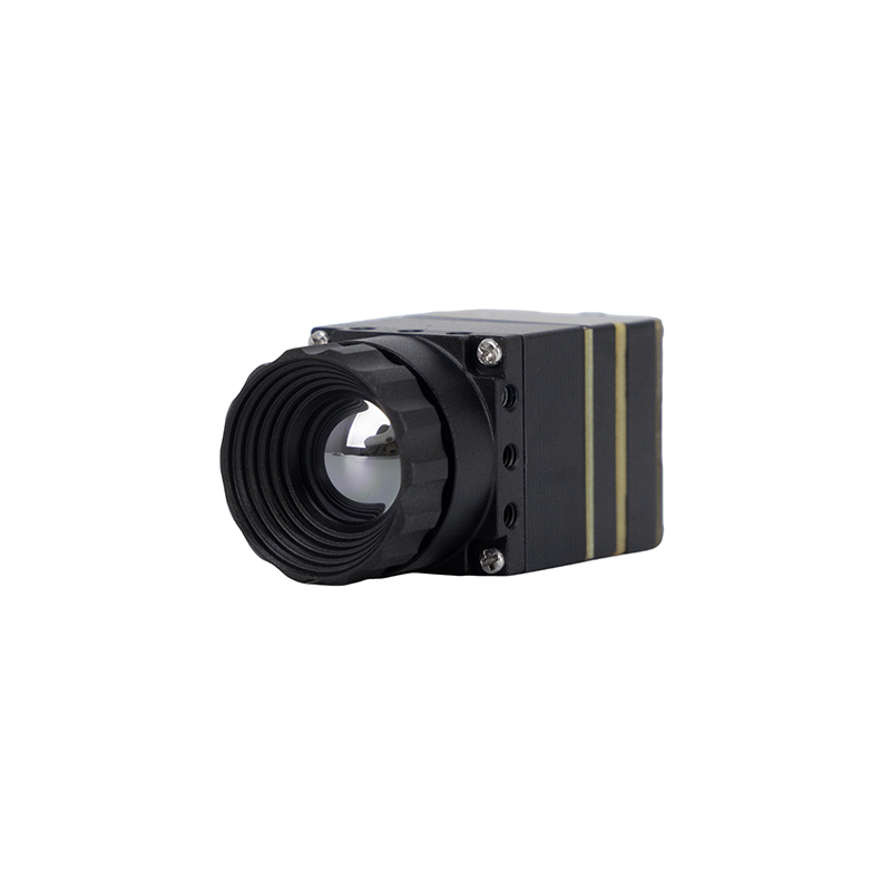
MD Series 384×288 Uncooled Infrared Thermal Camera Module
The Purpleriver MD Series thermal camera module is engineered for industrial-grade precision in demanding applications including physical perimeter security, automated machinery temperature monitoring, electrical inspection, and unmanned system payloads. Powered by a high-sensitivity uncooled 12μm pixel pitch VOx microbolometer array operating at 384×288 resolution, it delivers sharp, high-contrast thermal imagery under harsh atmospheric conditions.
Featuring a compact, plug-and-play architecture, the MD Series provides flexible multi-interface connectivity supporting simultaneous or selectable CVBS (Analog), USB 2.0, and MIPI-CSI2 digital streams. Backed by hardware design expertise from HKUST and former Huawei HiSilicon engineering leadership, the module supports extensive OEM/ODM customization, including custom optical lens brackets, tailored ISP algorithm curves, and proprietary protocol adaptation.

Mini 640 Uncooled LWIR Thermal Camera Core Module for Drones
The Mini 640 uncooled infrared thermal imaging module delivers high-resolution thermal sensing in a micro-footprint format engineered for aerial drone gimbals, tactical FPV platforms, and portable robotics. Delivering 640×512 resolution (with selectable 640×480 modes) at a 12μm pixel pitch, this core provides crisp thermal imagery, exceptional edge sharpness, and minimal power consumption.
With an ultra-compact body size of just 21 mm × 21 mm, the Mini 640 integrates smoothly into constrained gimbal spaces. It offers versatile optical flexibility with an extensive selection of focal lengths: 5mm, 9mm, 13mm, 18mm, 35mm, 50mm, 75mm, 100mm, and 150mm athermalized Germanium lenses. Supporting direct CVBS analog composite video alongside USB UVC connectivity, it is engineered for stable operation and robust environmental adaptability across extreme industrial and aerial temperature regimes.
For complete technical datasheets and international distribution options, check out our Arabic technical analysis on industrial handheld monocular selection, as well as our Russian engineering guide on choosing an industrial thermal imager.
5. Electrical & Hardware Integration Playbook: Power, Impedance, and Multi-Bus Bridging
Dropping an analog thermal module into an embedded carrier PCB, PTZ enclosure, or drone payload requires careful layout choices. In the shop, we frequently see noise problems caused by mismatched impedance, noisy DC-DC converters, or poor grounding.
1. CVBS Transmission Line & Impedance Matching
Composite Video Baseband Signals are unbalanced analog lines that demand a strict source and load termination of $75\,\Omega$. Any impedance mismatch along your PCB traces or cabling creates signal reflections. On screen, this shows up as ghosting, ringing, edge blurring, or color burst phase distortion.
- ⚙️ PCB Trace Routing: Route the CVBS analog video trace as a coplanar waveguide with ground or microstrip reference calculated for $75\,\Omega \pm 5\%$ characteristic impedance. Keep the line as short as possible, and do not run it alongside high-speed digital clocks, SPI lines, or DC-DC switching nodes.
- ⚙️ Interconnect Cabling: In moving gimbal assemblies, use high-flex miniature $75\,\Omega$ coaxial cable like RG-179 with PTFE dielectric and silver-plated copper shielding. For fixed field installations running over 100 meters, use double-shielded RG-59 or RG-6 with full 360-degree shield grounding at the connector backshell.
- ⚙️ ESD & Surge Protection: Analog video ports are exposed to field wiring. Place an ultra-low capacitance Transient Voltage Suppressor (TVS) diode right at the connector. Keep diode junction capacitance under $C_D < 1.5\,\text{pF}$ to prevent high-frequency roll-off, with protection ratings up to $\pm 15\,\text{kV}$ air and $\pm 8\,\text{kV}$ contact per IEC 61000-4-2.
2. Power Supply Design and Ripple Suppression
Uncooled microbolometer ROICs and video DACs are sensitive to power rail fluctuations. Voltage ripple on the input rail will modulate sensor bias voltages, showing up as horizontal rolling hum bars, high-frequency raster noise, or fixed vertical striping.
- ⚙️ Power Sequencing & Regulation: Power the thermal core through a dedicated, low-noise Low-Dropout (LDO) linear regulator offering high Power Supply Rejection Ratio (PSRR > 70 dB at 100 kHz). Never power the analog module directly from a switching buck/boost regulator without an LC filter and ferrite bead stage.
- ⚙️ Decoupling Network: Place low-ESR ceramic decoupling capacitors (a $10\,\mu\text{F}$ X7R ceramic paired with $0.1\,\mu\text{F}$ and $100\,\text{pF}$ C0G/NP0 caps) directly adjacent to the module's VCC and GND pins to kill both low-frequency ripple and high-frequency RF noise.
3. Hybrid Architecture: Simultaneous Analog Display and Digital AI Processing
Modern field systems often employ a dual-bus hybrid topology. In this architecture, the analog CVBS video output routes through a slip ring directly to an analog 5.8 GHz transmitter or benchtop display, giving the operator an instantaneous visual stream regardless of computer health. Simultaneously, the core's digital interface (MIPI-CSI2 or USB) pushes raw 14-bit radiometric frames to an embedded Edge AI processor (such as an NVIDIA Jetson, Rockchip RK3588, or NXP i.MX8). The edge computer runs real-time target recognition (ATR), perimeter intrusion detection, or thermal threshold alarms without introducing a single millisecond of latency into the primary flight or operator monitor.
6. High-Reliability Industrial and Aerial Application Profiles
The core strengths of analog thermal modules—zero latency, electrical resilience, low wiring overhead, and direct video output—make them the ideal choice across several challenging industrial and field operational environments.
1. Tactical UAV Gimbal Payloads and FPV Drone Reconnaissance
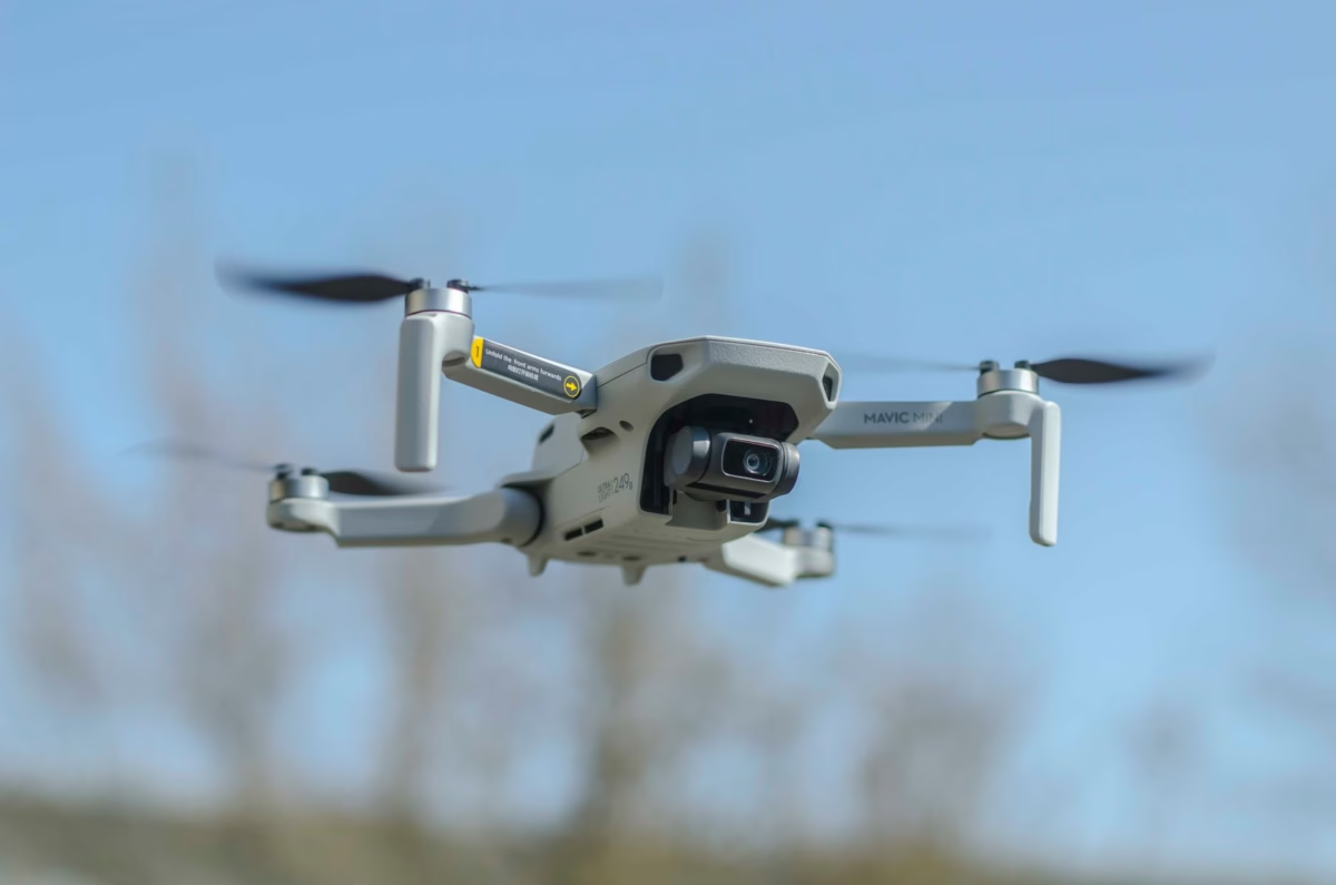
Small Unmanned Aerial Systems (sUAS) and First-Person View (FPV) drones operate under strict size, weight, and power limits. In dynamic flight regimes, digital compression latency degrades flight control and obstacle avoidance. Mounting an ultra-compact core like the Mini 640 ($21\,\text{mm} \times 21\,\text{mm}$) inside a 2-axis or 3-axis micro-gimbal allows direct transmission of live NTSC/PAL thermal video over an analog 5.8 GHz transmitter (VTX) to the pilot's goggles. The pilot navigates through fog, smoke, and tree canopies with zero buffer delay.
2. Legacy Security and Perimeter Surveillance Infrastructure Retrofits
Large industrial facilities—such as oil refineries, marine cargo terminals, substations, and chemical plants—often have miles of installed $75\,\Omega$ RG-59 coaxial cable. Replacing older visible-light analog CCTV cameras with MD Series 384×288 CVBS thermal modules enables full night and poor-weather thermal surveillance over the existing coaxial backbone. This saves thousands of dollars in recabling costs and avoids system downtime required for pulling new Cat6 Ethernet cable or installing PoE network switches in explosive or hazardous process areas.
3. High-Voltage Substation Monitoring & Industrial Process Automation
High-voltage transformer yards and metal casting plants generate severe electromagnetic fields and transient voltage spikes during switching cycles. In these areas, digital Ethernet PHYs can suffer from packet drops, buffer overruns, and network negotiation drops. Analog thermal camera cores operating over double-shielded coaxial lines provide superior electromagnetic immunity. They deliver non-contact thermal monitoring of busbars, disconnect switches, and refractory linings, alerting plant PLCs to dangerous hot spots before arc-flash or fire events occur.
Mini 640×512 Thermal Imaging Core Demo Video
7. Frequently Asked Questions (FAQ)
What is the main advantage of using an analog (CVBS) thermal camera module over digital formats?
Can Purpleriver thermal camera modules support both analog and digital output options simultaneously?
How does ambient temperature affect an uncooled thermal module, and how does the core compensate?
What is the difference between CVBS NTSC and PAL outputs on thermal camera modules?
📚 References & Further Reading
- Industry Standard: Learn more about core physics on the Wikipedia Thermal Imaging reference portal.
- Sourcing & Components: Sourcing verified optoelectronic subsystems through KUYANG Industrial Components.
- Application Analysis: Watch our technical deployment in the video guide of thermal imaging camera modules with drones.
- International Selection (Arabic): Read our regional guide on industrial handheld monocular selection in Arabic.
- Technical Guide (Russian): Explore our review on choosing an industrial thermal imager in Russian.