Analog Thermal Camera Modules: High-Precision CVBS & AI Thermal Cores for Industrial Integration
2026年8月17日
Vanadium Oxide Thermal Sensor Modules: High-Performance IR Imaging Cores for OEM Integration
2026年8月18日

The industrial thermal imaging landscape is undergoing a decisive technological transition from legacy analog thermal video infrastructures to native digital long-wave infrared (LWIR) camera architectures. For decades, original equipment manufacturers (OEMs) and embedded vision system integrators relied on standard-definition analog video standards like NTSC and PAL modulated across coaxial cable runs. But modern autonomous navigation platforms, automated optical inspection stations, intelligence, surveillance, and reconnaissance (ISR) payloads, and intelligent unmanned aerial vehicle (UAV) systems require real-time pixel-level radiometric fidelity, sub-millisecond transmission latencies, and direct compatibility with edge computing hardware.
Here's the deal: by cutting out intermediate digital-to-analog and analog-to-digital conversions, native digital thermal camera cores deliver uncompressed 14-bit or 16-bit raw data straight from the focal plane array (FPA) to embedded neural processing units (NPUs) and graphics processing units (GPUs). This architectural shift locks in deterministic temperature telemetry, maximizes the effective Noise Equivalent Temperature Difference (NETD), and guarantees the rock-solid data integrity demanded by state-of-the-art deep learning models like YOLOv8 and TensorRT-optimized convolutional neural networks. In this engineering guide, we will break down digital versus analog thermal cores, detailing sensor physics, readout circuit architectures, interface trade-offs, edge AI ingestion pipelines, and commercial OEM hardware setups.
Table of Contents
- 👉 1. Digital vs. Analog Thermal Camera Architectures: The Fundamental Paradigm Shift
- 👉 2. Microbolometer Physics & ROIC Conversion Mechanics
- 👉 3. Why Edge AI & Computer Vision Demand Pure Digital Radiometric Streams
- 👉 4. Digital Interface Deep Dive: MIPI CSI-2, USB 3.0, GigE Vision & LVDS
- 👉 5. Featured OEM Digital Thermal Camera Cores: Specifications & Benchmarks
- 👉 6. Step-by-Step Embedded Integration: Linux V4L2 Drivers to Edge AI
- 👉 7. Strategic OEM Selection Summary
- 👉 8. Comprehensive OEM Technical FAQ
1. Digital vs. Analog Thermal Camera Architectures: The Fundamental Paradigm Shift
The core distinction between analog and digital thermal architectures comes down to how the raw infrared signal is transduced, processed, and shipped across the wire. In legacy analog thermal camera cores, the thermal signal runs through multiple conversion stages that inject noise, choke dynamic range, and throw away the physical temperature calibration metrics essential for autonomous vision analytics.
Look, in a standard analog thermal core, the infrared sensor outputs an electrical signal that gets amplified and pre-processed internally, but is immediately routed through an onboard video Digital-to-Analog Converter (DAC). That DAC flattens the high-resolution thermal data into an analog composite video baseband signal (CVBS), structured around old-school NTSC or PAL broadcast timings. When that signal hits an embedded computing host or base station, it has to pass through an analog frame grabber with an Analog-to-Digital Converter (ADC) just to get turned back into bits for display or basic image processing.
In the shop, we see this dual-conversion pipeline cause major headaches across industrial and defense applications:
- ⚠️ Destructive Quantization and Dynamic Range Loss: The natural dynamic range of an uncooled long-wave infrared sensor covers 14 bits (16,384 discrete levels) to 16 bits (65,536 discrete levels). Analog composite video standards are structurally capped at 8-bit visual rendering (a measly 256 grayscale levels). To cram that data in, the camera processor applies aggressive Automatic Gain Control (AGC) or dynamic range compression, permanently stripping out the underlying linear Kelvin temperature data. The host processor gets only relative visual contrast rather than absolute radiometric numbers.
- ⚠️ Electromagnetic Interference and Transmission Attenuation: Analog voltage waveforms sent over coax or slip rings in robotic gimbals are wide open to electromagnetic interference (EMI) from electric motors, servos, and switching power supplies. High-frequency signal drop over long runs creates edge blurring, ghosting, and 50/60 Hz ground loop hum bars that cause computer vision algorithms to trip over false positives.
- ⚠️ Interlacing Artifacts and Temporal Latency: Legacy broadcast formats split 30 Hz or 25 Hz video streams into interlaced fields of alternating odd and even lines. In fast-moving applications like high-speed drones or industrial robotic arms, fast targets produce nasty jagged edge combing artifacts. On top of that, the combined lag of video encoding, analog transmission, and frame grabber decoding routinely introduces 35 to 70 milliseconds of latency—making analog streams a complete non-starter for closed-loop flight control or real-time obstacle avoidance.
Pure Digital Signal Chains: Direct-from-Sensor Uncompressed Radiometry
Native digital thermal camera architectures eliminate intermediate modulation entirely. Inside a native digital engine, the microbolometer sensor array converts long-wave infrared photons into electrical resistance shifts, which are immediately digitized at the sensor level by high-precision on-die ADCs. The resulting uncompressed 14-bit or 16-bit binary words stream directly across high-speed digital buses—such as MIPI CSI-2, USB 3.0, LVDS, or Gigabit Ethernet—straight into host processor memory using direct memory access (DMA).
When you build around a native digital architecture, you gain three huge engineering advantages:
- ✅ Bit-Depth and Radiometric Preservation: Every single pixel within the sensor matrix retains its exact 14-bit or 16-bit linear radiometric value. The host processor gets true radiometric telemetry where integer pixel values map directly to absolute scene temperatures.
- ✅ Deterministic Signal Integrity: Digital differential signaling protocols use packetized data delivery backed by cyclic redundancy checks (CRC). The digital frame received in system RAM is bit-for-bit identical to what left the sensor, completely immune to cable voltage drops or motor EMI.
- ✅ Simultaneous Multi-Stream Processing: Modern digital signal processors (DSPs) and field-programmable gate arrays (FPGAs) inside the core can pump out dual streams simultaneously: an uncompressed 16-bit radiometric Y16 stream dedicated to back-end AI math, and an 8-bit AGC-enhanced visual stream (like YUV or RGB) tailored for human operator displays.
2. Microbolometer Physics & ROIC Conversion Mechanics
To really understand why a digital infrared architecture outperforms analog, you have to look at the physical transduction and readout mechanisms happening inside the focal plane array. High-performance uncooled thermal imaging systems operate within the 8 µm to 14 µm atmospheric transmission window using a micro-electro-mechanical system (MEMS) sensor grid known as a microbolometer.
The Transduction Mechanism: From Photon Flux to Resistance Shifts
Each pixel in a microbolometer focal plane array consists of a micro-machined infrared absorption membrane suspended above a silicon substrate by micro-fabricated thermal isolation legs. The active thermistor material on the membrane is typically Vanadium Oxide (VOx) or Amorphous Silicon (a-Si), chosen for their high Temperature Coefficient of Resistance (TCR).
When long-wave infrared radiation emitted by an object in the field of view hits the suspended membrane, the absorbed radiant energy causes a micro-thermal rise in the membrane's thermal mass. That temperature shift triggers a proportional change in the electrical resistance of the VOx or a-Si thermistor layer. The relationship governing this physical shift is expressed as:
ΔR = R0 · β · ΔTd
Where R0 is the nominal unbiased electrical resistance of the pixel, β is the Temperature Coefficient of Resistance (typically -2% to -3% per Kelvin for high-performance VOx thin films), and ΔTd is the actual temperature change of the detector membrane resulting from the absorbed incident infrared flux.
Readout Integrated Circuit (ROIC) Digitization Architecture
Directly beneath the suspended MEMS array lies the Readout Integrated Circuit (ROIC). During each frame integration interval, the ROIC applies a precise bias voltage or bias current to each pixel. The resulting current, which tracks the thermal resistance shift of the membrane, is integrated across a Capacitive Transimpedance Amplifier (CTIA) or current-mirror integration stage.
In modern digital thermal cores, the ROIC uses a column-parallel architecture where dedicated on-chip successive approximation register (SAR) or sigma-delta (ΣΔ) analog-to-digital converters (ADCs) sit directly at the end of each pixel column. This allows the analog charge integration to be converted into high-depth 14-bit or 16-bit digital binary words right on the silicon die before the signal travels across any circuit board traces.
Digitizing the signal at the earliest possible stage inside the ROIC dramatically cuts electrical noise coupling. This structural efficiency allows modern cores to achieve exceptional thermal sensitivity, characterized by a Noise Equivalent Temperature Difference (NETD) of ≤ 30 mK to 40 mK at f/1.0. As a result, the digital sensor resolves temperature deltas smaller than 0.03°C without signal degradation.
3. Why Edge AI & Computer Vision Demand Pure Digital Radiometric Streams
Modern embedded vision platforms running deep learning models—such as YOLOv8, SSD-MobileNet, or custom semantic segmentation networks—on edge processors like the NVIDIA Jetson Orin, Rockchip RK3588, or specialized expansion hardware from Waveshare require clean, deterministic input data. Feeding analog thermal inputs through frame grabbers cripples AI model performance and eliminates true radiometric analytics.
The Problem with Analog Frame-Grabbed Data in Machine Learning
When an analog thermal stream gets digitized into an 8-bit format using a capture card, the host software only receives pixel values ranging from 0 to 255. Because the camera core applies dynamic range compression (such as histogram equalization) to keep the image visually clear for human eyes, the relationship between pixel values and actual temperatures changes constantly.
For example, if a hot vehicle drives into the background of an analog surveillance stream, the camera's internal AGC algorithm immediately rebalances the entire scene's contrast. As a consequence, the pixel values representing a person walking in the foreground will drop from a value of 210 down to 140, even though the person's physical body temperature has not changed at all. This value shifting wreaks havoc on convolutional neural network (CNN) feature extraction layers, causing bounding boxes to flicker, classification outputs to drop out, and object trackers to fail completely.
The Advantages of Uncompressed Y16 Digital Streams for Inference
Feeding a native digital 14-bit or 16-bit radiometric stream (Y16 format) directly into edge inference engines gives automated vision pipelines a massive edge:
- ✅ Invariant Physical Feature Extraction: In a linear Y16 digital radiometric stream, each discrete numerical step matches a fixed temperature interval (such as 0.01 Kelvin per LSB). A human target at 37°C outputs the exact same integer value regardless of what hot or cold objects enter or leave the background. This physical stability helps deep learning models generalize across changing operational environments.
- ✅ Multi-Spectral Sensor Fusion: Native digital streams can be ingested directly into GPU memory buffers and stacked alongside RGB visual channels to form 4-channel tensors (Red, Green, Blue, Thermal-16). This architecture enables dependable target tracking in zero-visibility conditions like thick fog, dust, smoke, and pitch darkness.
- ✅ Direct Mathematical Filtering: Embedded developers can run mathematical image processing filters—such as gradient edge detectors, adaptive thresholding, and temperature delta alarms—directly on the calibrated radiometric matrix. For an in-depth operational analysis of integrating high-resolution uncooled sensors into embedded platforms, check out our technical guide on USB-enabled, Raspberry Pi compatible 1280x1024 thermal imaging cores.
4. Digital Interface Deep Dive: MIPI CSI-2, USB 3.0, GigE Vision & LVDS
When designing an embedded thermal imaging product, system architects must select the physical communication interface that best fits their size, weight, power, and cost (SWaP-C) constraints, processing setup, and cabling distance requirements.
1. MIPI CSI-2 (Camera Serial Interface)
MIPI CSI-2 is the gold standard for ultra-compact, high-performance embedded systems where ultra-low latency, light weight, and minimal power consumption are must-haves.
- ⚙️ Physical Layer: Runs high-speed differential D-PHY signaling across 1, 2, or 4 lanes, providing throughput over 1.5 Gbps per lane.
- ⚙️ Latency Profile: Delivers sub-millisecond transmission latency by writing incoming image data straight into host system memory using Direct Memory Access (DMA), completely bypassing CPU overhead.
- ⚙️ Target Applications: Built for micro-drone gimbals, stabilized airborne camera balls, handheld thermal scopes, and compact robotics running NVIDIA Jetson, NXP i.MX8, or Rockchip SoCs.
2. USB 3.0 / USB-C (UVC + CDC Telemetry)
The USB 3.0 standard offers unmatched plug-and-play versatility for modular computing environments and rapid commercial prototyping.
- ⚙️ Protocol Architecture: Uses standard USB Video Class (UVC) for transferring uncompressed 16-bit (Y16) raw video frames alongside an independent USB Communications Device Class (CDC) virtual COM port for bidirectional serial commands, calibration parameter updates, and temperature telemetry queries.
- ⚙️ Target Applications: Medical diagnostic instruments, laboratory test benches, automated factory vision stations, and rapid integration with x86 and ARM-based industrial single-board computers.
3. GigE Vision / IP Streaming
GigE Vision and Ethernet-based IP streaming standards provide long transmission distances in distributed industrial plant automation.
- ⚙️ Protocol Architecture: Uses standard UDP/IP network stacks and the GenICam protocol standard, permitting high-bandwidth 16-bit radiometric data transfer across CAT6 structured cabling over distances up to 100 meters without signal boosters.
- ⚙️ Target Applications: Continuous flare stack monitoring, electrical substation switchyard surveillance, industrial automation quality control, and wide-area perimeter security.
4. Parallel CMOS / LVDS
Low-Voltage Differential Signaling (LVDS) and parallel digital CMOS buses deliver direct chip-to-chip connectivity for dedicated hardware implementations.
- ⚙️ Protocol Architecture: Streams raw digital pixel words synchronously with dedicated pixel clock, line valid, and frame valid strobes directly into Field Programmable Gate Arrays (FPGAs) or digital signal processors.
- ⚙️ Target Applications: Defense-grade target acquisition systems, specialized electro-optical tracking sights, and custom hardware pipelines requiring deterministic, zero-jitter timing synchronization.
When deploying systems globally, make sure your software stack complies with localized API requirements. Integrators can consult our Polish thermal core integration manual or review our Russian technical engineering knowledgebase for multi-regional software and driver deployments.
5. Featured OEM Digital Thermal Camera Cores: Specifications & Benchmarks
To demonstrate the real-world performance available to system integrators, the following high-grade digital LWIR camera modules highlight the capabilities of modern uncooled thermal imaging hardware.
Product Showcase 1: High Resolution Uncooled Infrared 1280*1024 Thermal Imaging LWIR Camera
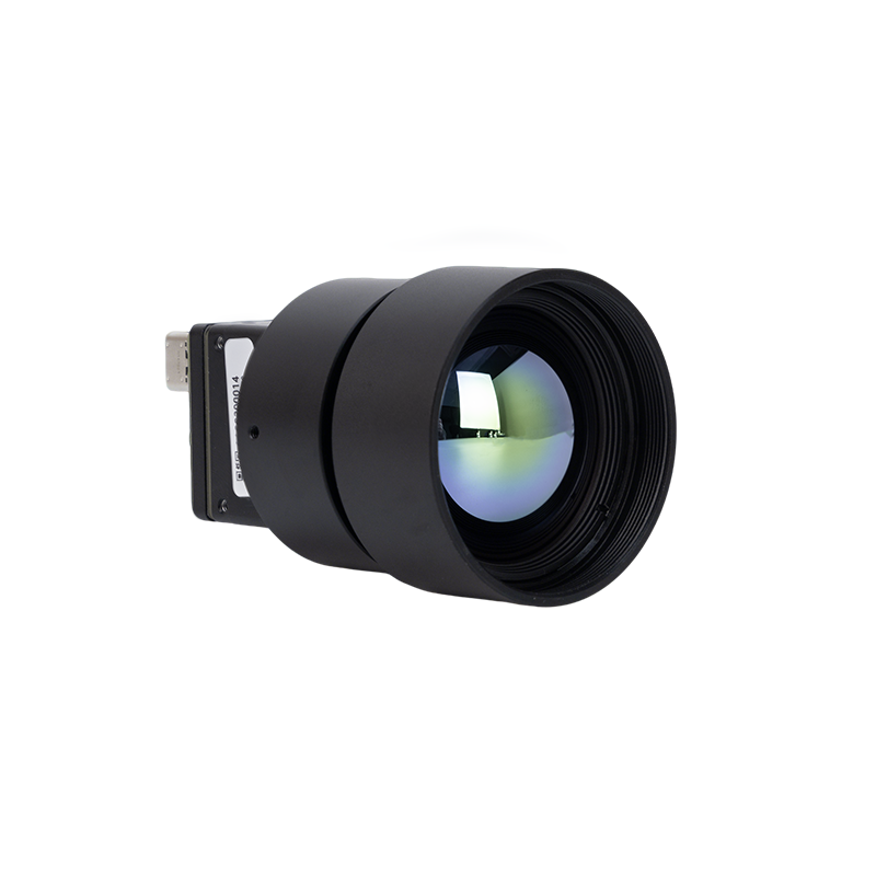
The High Resolution Uncooled Infrared 1280*1024 Thermal Imaging LWIR Camera is a top-tier industrial core engineered for applications requiring exceptional thermal detail and wide-area coverage. Featuring an ultra-dense 1.31-megapixel focal plane array with a fine 12 µm pixel pitch, this module captures high-definition thermal signatures across the 8 µm to 14 µm spectral band. Outfitted with a premium 25mm optical lens assembly, this core provides long-range detection, high dynamic range radiometry, and native digital output, making it ideal for integration into advanced border security, defense surveillance, and high-throughput automated inspection systems.
| Specification Parameter | Engineering Detail / Measured Value |
|---|---|
| Sensor Array Resolution | 1280 × 1024 Pixels (SXGA Resolution) |
| Pixel Pitch & Detector Type | 12 μm Uncooled Vanadium Oxide (VOx) Microbolometer |
| Spectral Range | 8 μm to 14 μm (LWIR Window) |
| Optical Configuration | 25mm High-Transmission Germanium Lens |
| Data Output Modes | Native 14-Bit / 16-Bit Raw Digital Radiometric Stream |
| Target Deployments | Border Reconnaissance, AI Optical Sorting, Long-Range Industrial Monitoring |
View Product Details & Pricing ➔
Product Showcase 2: Uncooled LWIR Mini 256*192 Thermal Imaging Camera Module Similar To DJI For Detecting Mines
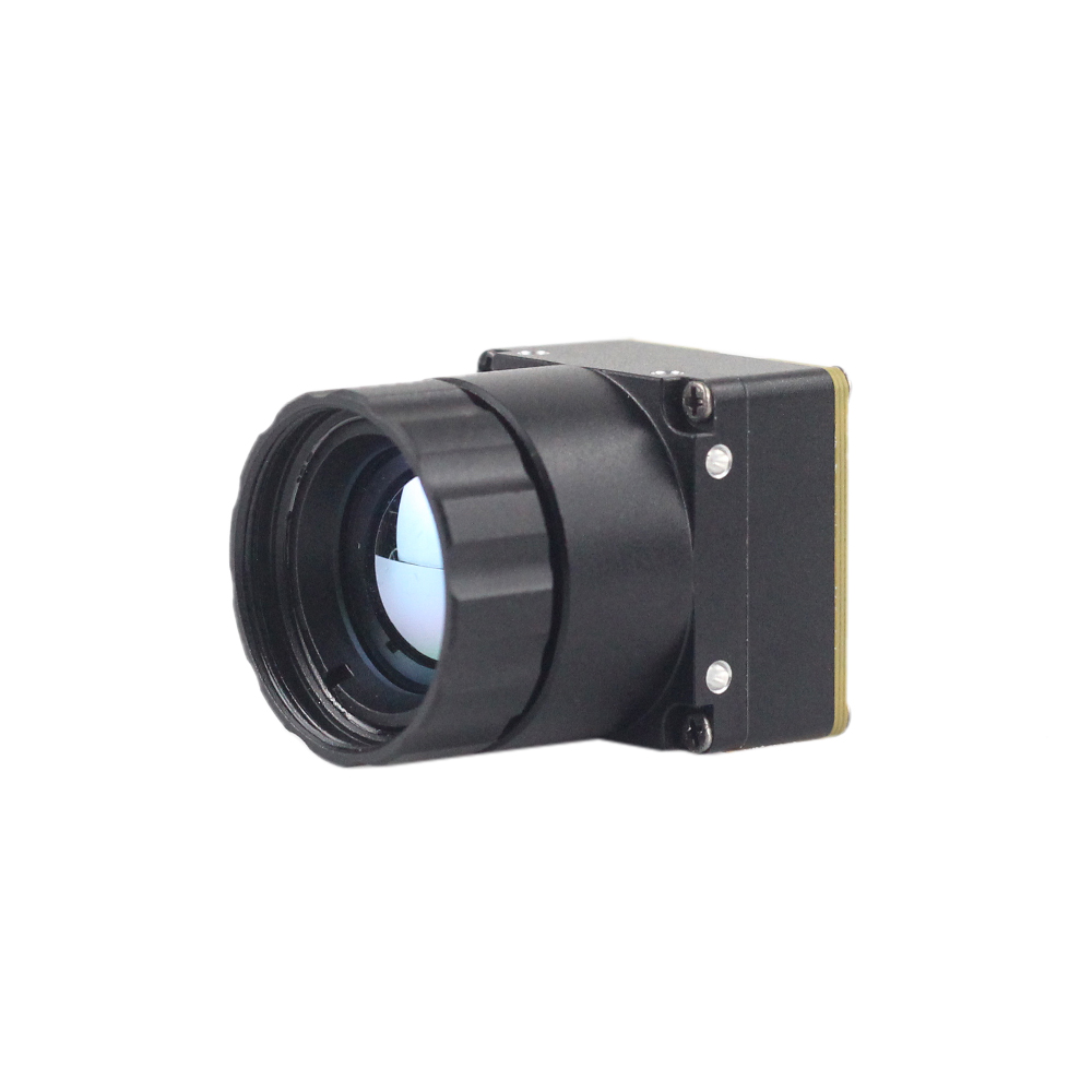
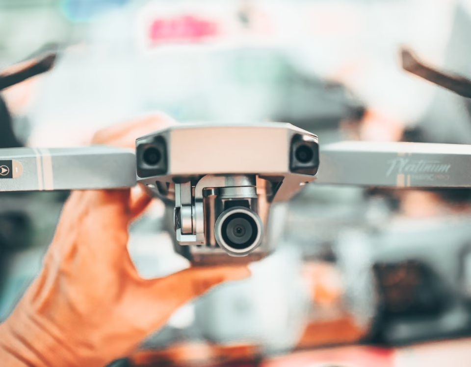
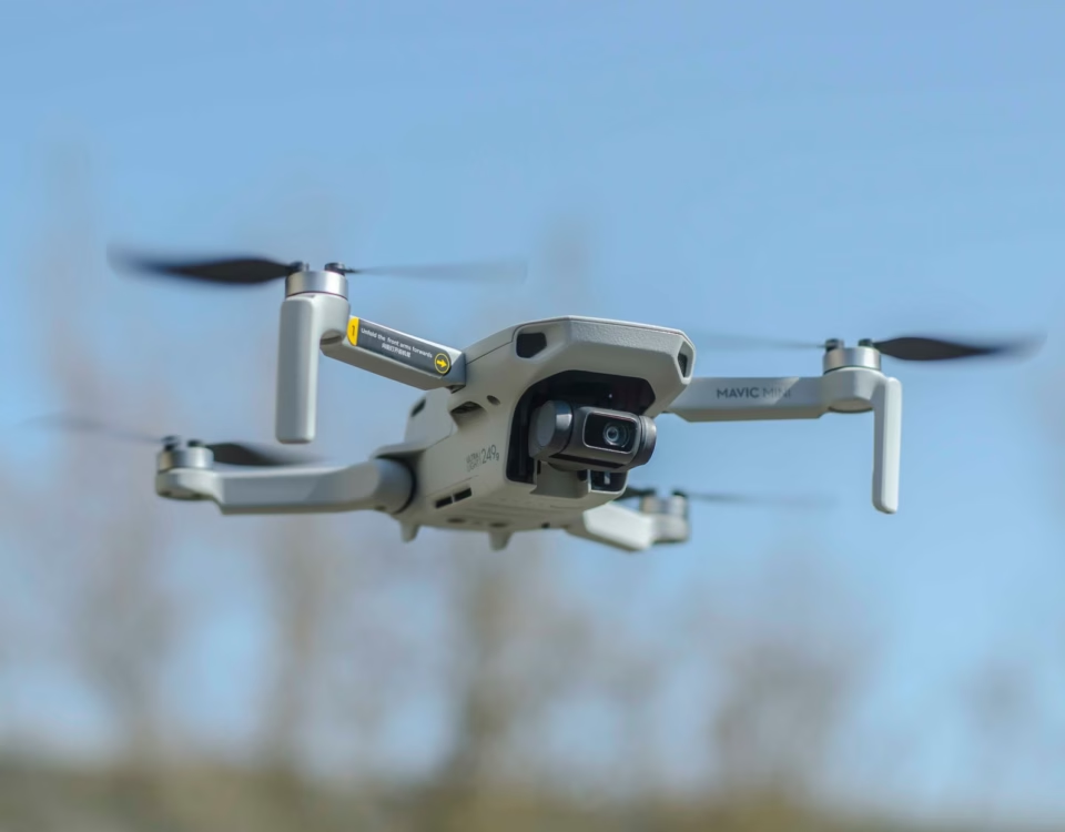
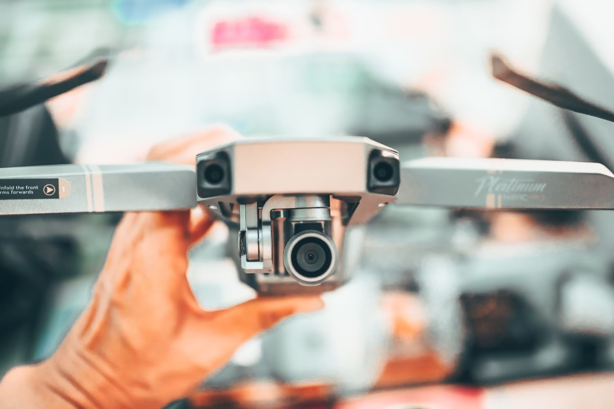
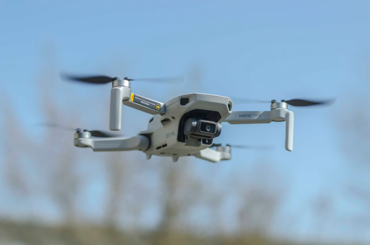
The Uncooled LWIR Mini 256*192 Thermal Imaging Camera Module Similar To DJI For Detecting Mines is engineered specifically for size-, weight-, and power-constrained (SWaP) integrations, such as micro-drones, robotic crawlers, and compact security payloads. Adopting high-performance infrared detectors, it delivers ultra-clear thermal imaging combined with accurate temperature measurement. It captures ambient infrared radiation and outputs a uniform, high-contrast thermal image with full radiometry, providing the precise temperature differentials needed to detect buried landmines, perform structural building diagnostics, and execute low-altitude aerial inspections.
| Specification Parameter | Engineering Detail / Measured Value |
|---|---|
| Sensor Array Format | 256 × 192 Pixels (High Sensitivity Array) |
| Detector Technology | High-Performance Uncooled LWIR VOx Microbolometer |
| Radiometric Calibration | Accurate Temperature Measurement with Full Surface Radiometry |
| SWaP Optimization Profile | Ultra-Miniature Lightweight Architecture (DJI-Class Payload Ready) |
| Output Format | Uniform Digital Thermal Stream with Radiometric Metadata |
| Primary Mission Scope | Sub-Surface Landmine Detection, Micro-UAV Payloads, Search & Rescue |
View Product Details & Pricing ➔
6. Step-by-Step Embedded Integration: Linux V4L2 Drivers to Edge AI
Hooking up a native digital thermal camera module to an embedded Linux system means configuring the kernel capture driver, verifying the raw 16-bit video device node, and setting up an efficient zero-copy pipeline to feed radiometric frames straight into edge AI models.
Step 1: Kernel Driver Binding and V4L2 Enumeration
When connected via USB 3.0 or MIPI CSI-2, the digital thermal core binds into the Linux Video4Linux2 (V4L2) driver framework. The camera creates a video device node (such as /dev/video0) supporting uncompressed 16-bit grayscale capture (V4L2_PIX_FMT_Y16).
You can verify format support directly from the Linux terminal using v4l2-ctl:
# Query camera capabilities and supported pixel formats
v4l2-ctl --device=/dev/video0 --list-formats-ext

# Expected output confirming 16-bit radiometric streaming:
# [0]: 'Y16 ' (16-bit Greyscale)
#       Size: Discrete 1280x1024 (or 256x192)
#       Interval: Discrete 0.033s (30.000 fps)
Step 2: Python / OpenCV Zero-Copy Radiometric Extraction
Once the device node is up, software engineers can build an ingestion loop in Python or C++. The snippet below demonstrates how to capture raw 16-bit radiometric data, map raw pixel values to calibrated Celsius temperatures, and prep the frame for AI inference:
import cv2
import numpy as np

def initialize_thermal_stream(device_index=0):
    # Open capture node using direct V4L2 backend
    cap = cv2.VideoCapture(device_index, cv2.CAP_V4L2)

    # Configure capture parameters for native 16-bit raw transfer
    cap.set(cv2.CAP_PROP_FOURCC, cv2.VideoWriter_fourcc(*'Y', '1', '6', ' '))
    cap.set(cv2.CAP_PROP_CONVERT_RGB, 0) # Bypass 8-bit auto-conversion

    if not cap.isOpened():
        raise RuntimeError("Failed to establish link with digital thermal camera core.")
    return cap

def process_radiometric_frame(cap):
    ret, raw_y16_frame = cap.read()
    if not ret:
        return None, None

    # Step A: Compute true Celsius temperature matrix
    # Transfer function: (Raw_Value / 100.0) - 273.15 -> Absolute Celsius
    celsius_matrix = (raw_y16_frame.astype(np.float32) / 100.0) - 273.15

    # Step B: Identify hotspot coordinates for AI bounding-box tracking
    min_temp, max_temp, min_loc, max_loc = cv2.minMaxLoc(celsius_matrix)

    # Step C: Generate an 8-bit visual stream for operator display using normalization
    norm_display = cv2.normalize(raw_y16_frame, None, 0, 255, cv2.NORM_MINMAX, dtype=cv2.CV_8U)
    colorized_frame = cv2.applyColorMap(norm_display, cv2.COLORMAP_INFERNO)

    return celsius_matrix, colorized_frame, max_temp, max_loc

# Example execution loop
if __name__ == "__main__":
    thermal_cap = initialize_thermal_stream(0)
    print("Capturing digital thermal data stream...")

    try:
        while True:
            temp_data, display_img, peak_temp, peak_pos = process_radiometric_frame(thermal_cap)
            if temp_data is None:
                break

            # Embed real-time telemetry text onto visual stream
            telemetry_str = f"Max: {peak_temp:.2f} C at {peak_pos}"
            cv2.putText(display_img, telemetry_str, (15, 30),
                        cv2.FONT_HERSHEY_SIMPLEX, 0.7, (0, 255, 255), 2)

            cv2.imshow("Digital LWIR Core - Engineering Feed", display_img)
            if cv2.waitKey(1) & 0xFF == ord('q'):
                break
    finally:
        thermal_cap.release()
        cv2.destroyAllWindows()
7. Strategic OEM Selection Summary
Choosing the right digital thermal camera core interface comes down to matching host processing capabilities with the physical constraints of your target platform. Here is how the key interfaces stack up:
| System Design Priority | Recommended Interface | Key Architectural Advantage |
|---|---|---|
| Drone Gimbals & Micro-UAV Payloads | MIPI CSI-2 | Sub-5ms glass-to-memory latency, minimal weight, zero CPU overhead via DMA. |
| Rapid SBC Prototyping & Medical Diagnostics | USB 3.0 Type-C | Standard UVC cross-platform compatibility, simplified single-cable power and data. |
| Distributed Industrial Automation & Security | GigE Vision / IP | Transmission range up to 100 meters over standard CAT6 cabling; GenICam standardization. |
| Custom High-Reliability Defense Platforms | Parallel / CMOS / LVDS | Direct synchronous clock coupling into custom OEM FPGAs with deterministic timing. |
8. Comprehensive OEM Technical FAQ
What does 'digital' mean in modern infrared thermal imaging compared to legacy analog systems?
Why are digital thermal camera modules essential for commercial drones and AI applications?
How does Non-Uniformity Correction (NUC) differ between digital and analog thermal cores?
Can a digital thermal core stream raw temperature data and visual palettes concurrently?
What factors determine the maximum frame rate and latency in digital thermal modules?
📚 References & Further Reading
- Industry Standard: Wikipedia Microbolometer Overview & Physics
- Hardware Acceleration Partner: Waveshare Embedded Vision Platforms & Interfaces
- Related Technical Guide: High-Resolution 1280x1024 USB Uncooled Thermal Core Architecture
- Regional Documentation (PL): Polish Embedded Thermal Module Deployment Manual
- Regional Documentation (RU): Russian Industrial Infrared Technical Knowledgebase