شراء نواة الكاميرا الحرارية: دليل وحدات LWIR عالية الأداء 640 و384
11 سبتمبر 2026
وحدة كاميرا حرارية MIPI: دمج الأشعة تحت الحمراء طويلة الموجة (LWIR) بزمن انتقال منخفض للطائرات المسيّرة والذكاء الاصطناعي الطرفي
في هندسة الرؤية المدمجة، يطرح دمج استشعار الأشعة تحت الحمراء طويلة الموجة (LWIR) في معماريات طرفية مدمجة ذاتية التشغيل تحديات كبيرة على مستوى النظام. فالنوى الحرارية التقليدية المرتبطة ببروتوكولات USB 3.0 (UVC) أو الواجهة الطرفية التسلسلية (SPI) تُدخل في كثير من الأحيان أعباءً إضافية على وحدة المعالجة المركزية للمضيف، وزمن انتقال غير قابل للإدارة في التخزين المؤقت للنواة، وتذبذبًا غير حتمي في الحزم، واختناقات شديدة في عرض نطاق الإرسال. وبالنسبة للمنصات الطرفية المقيّدة بمعايير SWaP (الحجم والوزن والطاقة والتكلفة) — مثل الطائرات المسيّرة الدقيقة، والمحاور الدقيقة التكتيكية، والروبوتات المتحركة ذاتية التشغيل، وبوابات رؤية الذكاء الاصطناعي الطرفية — تؤدي هذه الاختناقات البروتوكولية إلى تدهور أداء الرؤية الحاسوبية في الزمن الحقيقي، وإضعاف حلقات تثبيت PID للمحور، ورفع زمن المعالجة الكلي إلى ما يتجاوز العتبات الحتمية.
الحل المعماري المعياري في الصناعة هو الدمج المباشر لوحدة وحدة كاميرا حرارية MIPI عبر طبقة النقل MIPI CSI-2 (الواجهة التسلسلية للكاميرا 2). فمن خلال ربط قراءات مستشعر الميكروبولومتر غير المبرّد مباشرة بمعالج الإشارات الضوئية (ISP) الأصلي لمعالج التطبيقات ومحرك الوصول المباشر للذاكرة (DMA)، يتجاوز مهندسو النظم طبقات ترجمة بروتوكولات نظام التشغيل بالكامل. ويتيح هذا التحول المعماري نقلًا حتميًا دون المللي ثانية لبيانات إشعاعية خام غير مضغوطة بدقة 14 بت أو 16 بت بمعدلات إطارات عالية (30 هرتز إلى 60 هرتز) مباشرة إلى مساحات ذاكرة موحدة يمكن لوحدة معالجة الرسومات ووحدة المعالجة العصبية الوصول إليها، مما يفتح الباب أمام الاستدلال بالذكاء الاصطناعي الطرفي في الزمن الحقيقي، ودمج المستشعرات متعددة الأطياف، وتتبع الأهداف، والتصوير الحراري الصناعي الآلي.
جدول المحتويات
- 👉 فيزياء ومعمارية بروتوكول MIPI CSI-2 في تصوير الأشعة تحت الحمراء طويلة الموجة
- 👉 حزمة البرمجيات المدمجة: معمارية مشغّل V4L2 وشجرة الأجهزة وخطوط الأنابيب بدون نسخ
- 👉 معالجة البيانات الإشعاعية وتسريع عتاد الذكاء الاصطناعي الطرفي
- 👉 الهندسة العتادية وتحسين SWaP-C والتصميم الكهروضوئي
- 👉 عرض تقني لوحدات MIPI الحرارية الصناعية ومصفوفة المواصفات
- 👉 دليل التكامل خطوة بخطوة ودليل استكشاف الأخطاء وإصلاحها
- 👉 الأسئلة الشائعة المتعمقة حول التكامل الصناعي
فيزياء ومعمارية بروتوكول MIPI CSI-2 في تصوير الأشعة تحت الحمراء طويلة الموجة
تعمل مستشعرات التصوير الحراري بشكل جوهري مختلف عن مستشعرات CMOS القياسية للطيف المرئي. تستخدم كواشف الأشعة تحت الحمراء طويلة الموجة غير المبرّدة مصفوفات المستوى البؤري للميكروبولومتر — المصنوعة عادةً من أكسيد الفاناديوم (VOx) أو السيليكون غير المتبلور (α-Si) — الحساسة للإشعاع الكهرومغناطيسي ضمن نافذة النقل الجوي من 8 ميكرومتر إلى 14 ميكرومتر. يتكون كل بكسل ميكروبولومتر من ماص للأشعة تحت الحمراء معلق فوق ركيزة سيليكونية عبر أرجل عزل حراري مجهرية. وعند التعرض للإشعاع الحراري الساقط، تتغير درجة حرارة الماص، مما يسبب تغيرًا قابلًا للقياس في مقاومته الكهربائية. ويتم ترقيم هذا التغير التناظري في المقاومة بواسطة دوائر القراءة المتكاملة (ROICs) إلى قيم خام عالية المدى الديناميكي، عادةً بأرقام رقمية بدقة 14 بت أو 16 بت لكل بكسل.
يتطلب نقل تدفقات بيانات الميكروبولومتر الخام هذه إلى معالج مضيف مدمج واجهة تحافظ على سلامة الإشارة دون إدخال زمن انتقال حسابي. وتلبي الواجهة التسلسلية للكاميرا MIPI CSI-2، المقترنة بالطبقة الفيزيائية (D-PHY)، هذه المتطلبات لأنظمة الرؤية المدمجة من خلال نقل بيانات البكسل المتسلسلة عبر مسارات تفاضلية من نقطة إلى نقطة تحكمها ساعة عتادية صارمة.

ديناميكيات إرسال الطبقة الفيزيائية MIPI D-PHY
تعتمد الطبقة الفيزيائية الكهربائية لوحدة MIPI الحرارية الحديثة على مواصفة MIPI Alliance D-PHY، وهي واجهة غير متزامنة متزامنة المصدر تتميز بمسار ساعة تفاضلي واحد ومسار بيانات تفاضلي واحد أو اثنين أو أربعة. تتبدل الطبقة الفيزيائية ديناميكيًا بين وضعي إرسال تشغيليين:
- ⚙️ وضع السرعة العالية (HS): يعمل باستخدام الإرسال التفاضلي منخفض الجهد (شبيه بـ LVDS)، مع تأرجح تفاضلي اسمي قدره 200 mV متمركز حول جهد الوضع المشترك 200 mV (V١. سم). في وضع HS، تُسلسل البيانات وتُنقل بمعدلات إنتاجية تتراوح من 80 Mbps حتى 2.5 Gbps لكل مسار، مما يتيح إنتاجية إجمالية عالية مع انبعاثات كهرومغناطيسية مشعة منخفضة بشكل استثنائي.
- ⚙️ وضع الطاقة المنخفضة (LP): يعمل باستخدام منطق إرسال CMOS أحادي الطرف بجهد 1.2 V. يدير وضع LP بروتوكولات التحكم في الخط، ويتولى مصافحات مزامنة الإطار (مثل بدء الإرسال [SoT] ونهاية الإرسال [EoT])، وانتقالات حالة الطاقة المنخفضة، وأوضاع السكون (LP-11).
على النقيض من مستشعرات RGB المرئية بدقة 4K التي تتطلب إنتاجية متعددة الجيجابت (مثلًا، 4K بمعدل 60 إطارًا في الثانية تستهلك أربعة مسارات تعمل بأكثر من 1.5 Gbps لكل مسار)، فإن مستشعر LWIR غير المبرد الذي يعمل بدقة 640 × 512 مع خرج إشعاعي 16-بت بمعدل 50 هرتز ينتج حمولة بيانات خام إجمالية تُحسب على النحو التالي:
الإنتاجية = 640 × 512 × 16 بت/بكسل × 50 إطارًا/ثانية ≈ 262.14 Mbps
تُدار متطلبات الإنتاجية هذه بسهولة عبر مسار واحد (1-lane) أو مسارين (2-lane) من MIPI D-PHY يعملان بمعدل ساعة متحفظ يتراوح بين 400 Mbps و800 Mbps لكل مسار. إن التشغيل بترددات ساعة أقل مع استخدام إرسال D-PHY التفاضلي الأصلي يقلل من التداخل الكهرومغناطيسي عالي التردد (EMI) عبر مستقبلات التردد اللاسلكي المجاورة، وهي ميزة حاسمة عند دمج مستقبلات الاتصالات الحساسة ومستقبلات GNSS في منصات الطائرات بدون طيار المدمجة.
بروتوكول حزم CSI-2 وأنواع البيانات الإشعاعية
في طبقة بروتوكول CSI-2، تُرسل بيانات الصورة في حزم منظمة تتكون من ترويسة حزمة (PH) بطول 4 بايت، وتسلسل بيانات حمولة بطول عشوائي، وتذييل حزمة (PF) بطول 2 بايت يحمل فحص تكرار دوري (CRC) بطول 16-بت. تحتوي ترويسة الحزمة على بايت معرّف البيانات (DI) بطول 8-بت، مكوّن من معرّف القناة الافتراضية (VC) بطول 2-بت ورمز نوع البيانات (DT) بطول 6-بت.
تستخدم الوحدات الحرارية أنواع بيانات محددة ضمن تدفق CSI-2 لنقل القياسات البولومترية والإشعاعية الخام:
- ⚙️ RAW14 (نوع البيانات 0x2D): بيانات غير مضغوطة بطول 14-بت. تنتج الميكروبولومترات نطاقًا ديناميكيًا يبلغ 14-بت بشكل أصلي. تُنسق الحزم عن طريق تعبئة أربع قيم بكسل بطول 14-بت في سبع بايتات متتالية بطول 8-بت، مما يزيد من كفاءة إرسال الحمولة عبر الوصلة الفيزيائية.
- ⚙️ RAW16 (نوع البيانات 0x2E): بيانات غير مضغوطة بطول 16-بت. يُربط كل بكسل مباشرة بعدد صحيح غير موقّع بطول بايتين يمثل إما استجابة الكاشف الخطية أو قيم درجة الحرارة الإشعاعية المطلقة بالسنتيكلفن. يبسّط RAW16 محاذاة البايتات وعنونة الذاكرة على المعالجات الدقيقة المضيفة.
- ⚙️ بيانات معرفة من المستخدم / مدمجة بطول 8-بت (أنواع البيانات 0x30 إلى 0x37 أو 0x12): تسبق الوحدات الحرارية الصناعية أو تُلحق "سطرًا مدمجًا" يحتوي على بيانات وصفية تشغيلية: درجة حرارة قالب المستشعر، وحالة الغالق الداخلي، وجهد الثرمستور في مبيت FPA، وأعلام المعايرة، وقراءات المحيط البصري اللازمة لحسابات القياس الإشعاعي المطلق.
مقارنة معمارية: MIPI CSI-2 مقابل الواجهات المدمجة البديلة
| معيار الواجهة | الطبقة الفيزيائية | أقصى إنتاجية مستدامة | زمن الانتقال من الزجاج إلى الذاكرة | العبء على وحدة المعالجة المركزية المضيفة | مساحة الموصل |
|---|---|---|---|---|---|
| MIPI CSI-2 | D-PHY تفاضلي (HS/LP) | حتى 2.5 جيجابت في الثانية لكل مسار | أقل من 1.5 مللي ثانية (DMA مباشر) | أقل من 2% (ISP/DMA عتادي) | محوري دقيق فائق الصغر أو FPC بسمك 0.5 مم |
| USB 3.0 / UVC | SuperSpeed تفاضلي | ~3.2 جيجابت/ثانية (مرتبط بالحزم) | 15 إلى 45 مللي ثانية (تذبذب متغير) | 12% إلى 25% (استقصاء ونسخ النواة) | مقابس USB Type-C أو Type-A ضخمة |
| SPI (رباعي/ثماني) | متزامن أحادي الطرف | ~50 إلى 100 ميجابت في الثانية | 40 إلى 120 مللي ثانية (محدود بالمخزن المؤقت) | 30% إلى 60% (حمل مقاطعة مرتفع) | رؤوس دبابيس قياسية من لوحة إلى لوحة |
| متوازي (DVP) | CMOS أحادي الطرف 8/14 بت | ~600 ميجابت في الثانية | 3 إلى 8 مللي ثانية | 5% إلى 10% | شريط عريض 30+ دبوس (ملف EMI مرتفع) |
حزمة البرمجيات المدمجة: معمارية مشغّل V4L2 وشجرة الأجهزة وخطوط الأنابيب بدون نسخ
الدمج المباشر لـ وحدة كاميرا حرارية MIPI في أنظمة SoC الحديثة لنظام Linux — مثل NVIDIA Jetson Orin/Xavier أو Rockchip RK3588 أو NXP i.MX8M أو Raspberry Pi Compute Module 4/5 — يتطلب تكوين حزمة برامج تشغيل النواة الأساسية. يتم تسجيل النوى الحرارية داخل إطار عمل فيديو فور لينكس 2 (V4L2) في Linux كأجهزة فرعية للكاميرا تُدار عبر واجهة برمجة تطبيقات Media Controller.
تتبع بنية نظام المضيف نموذج برامج تشغيل متعدد الطبقات: تلتقط نقطة نهاية مستقبل CSI-2 في SoC حزم البيانات التسلسلية التفاضلية الواردة، وتمررها إلى قناة DMA داخلية، وتنقل البيانات إلى مخازن الذاكرة الفعلية. يقوم برنامج تشغيل النواة بضبط معاملات البث عبر واجهة تحكم I2C أو UART، مما يضمن تزامن حالات التعريض والتأطير والمعالجة الحرارية على الشريحة.
بنية شجرة مصدر الجهاز (DTS)
تحدد شجرة جهاز Linux طوبولوجيا العتاد، وتربط نقطة نهاية مستقبل CSI-2 في SoC بمنفذ إخراج الوحدة الحرارية، وتحدد تكوينات الدبابيس لتوليد الساعة وخطوط إعادة التعيين وواجهة التحكم في الكاميرا (عادةً ناقل I2C يعمل في الوضع السريع عند 400 كيلوهرتز).
فيما يلي تنفيذ أساسي لعقدة DTS لنظام يشغل نواة حرارية MIPI ثنائية المسارات متصلة بـ SoC مدمج:
// مقتطف من شجرة مصدر الجهاز (DTS) لوحدة MIPI الحرارية الصناعية;
بالنسبة لمطوري الأنظمة المدمجة الذين يعملون على بنى هجينة بصرية-حرارية، فإن تقييم سير عمل تكامل العتاد المتخصص أمر بالغ الأهمية. تعرف على المزيد حول محاذاة طوبولوجيا المستشعرات والتكوينات ثنائية النطاق في دليل دمج وحدة الكاميرا الحرارية بمستشعر CMOS.
تنفيذ نواة برنامج تشغيل الجهاز الفرعي V4L2
ينفذ برنامج تشغيل النواة هياكل عمليات الجهاز الفرعي القياسية لـ V4L2: v4l2_subdev_core_ops, v4l2_subdev_video_ops, و v4l2_subdev_pad_ops. عندما تبدأ تطبيقات مساحة المستخدم التقاط الفيديو عبر استدعاء النظام VIDIOC_STREAMON ، يقوم برنامج التشغيل بتكوين FPGA أو ASIC الداخلي للنواة الحرارية عبر I2C، ويضع مستشعر الميكروبولومتر في وضع القراءة المستمرة، ويجهز مستقبل CSI-2 على جانب المضيف.
static const struct v4l2_subdev_video_ops thermal_video_ops = {
إدارة الذاكرة بدون نسخ عبر بنية DMABUF
لا يمكن لمعالجة الصور الإشعاعية عالية الإنتاجية أن تتحمل نسخ الذاكرة المدفوعة بوحدة المعالجة المركزية (memcpy) عبر حدود المستخدم والنواة. إن نقل إطارات 640 × 512 ذات 16 بت عند 50 هرتز باستخدام عمليات قراءة تقليدية يؤدي إلى إشباع ناقل الذاكرة وزيادة زمن وصول الإطار بمقدار 15 مللي ثانية إلى 30 مللي ثانية.
لتحقيق زمن وصول أقل من مللي ثانية، تستخدم خطوط المعالجة الطرفية الحديثة DMABUF لمشاركة الذاكرة:
- ⚙️ تخصيص المخازن المؤقتة: يتم تخصيص كتل ذاكرة متجاورة مسبقًا في ذاكرة الوصول العشوائي للنظام عبر مخصص الذاكرة المتجاورة في لينكس (CMA) أو مخصصات المخازن المؤقتة العتادية (مثل NVIDIA
NvBufSurfaceأو مجمعات ذاكرة Rockchip MPP/RGA). - ⚙️ تصدير الواصفات: يتم تصدير هذه المخازن المؤقتة المخصصة إلى تطبيقات مساحة المستخدم كواصفات ملفات لينكس أصلية (DMABUF FDs).
- ⚙️ البث عبر DMA العتادي: تقوم واجهة MIPI CSI-2 العتادية في SoC المضيف بنقل حمولات الحزم الواردة مباشرة إلى عناوين الذاكرة الفعلية هذه دون تدخل وحدة المعالجة المركزية المضيفة.
- ✅ Direct NPU/GPU Ingestion: Edge AI inference engines (such as TensorRT, DeepStream, or ONNX Runtime) bind directly to these shared memory pointers. Zero-copy access eliminates memory copying overhead and achieves glass-to-inference execution latencies below 1.5 milliseconds.
معالجة البيانات الإشعاعية وتسريع عتاد الذكاء الاصطناعي الطرفي
Unlike visible-spectrum image sensors that output ready-to-display sRGB color spaces, uncooled LWIR sensors capture raw thermal flux emitted across the scene. The digitized output corresponds to detector resistance rather than human visual perceptions. Developing real-time vision pipelines requires applying specialized calibrations and transformations to extract accurate temperature information.
Non-Uniformity Correction (NUC) and Bad Pixel Replacement (BPR)
Microbolometer focal plane arrays exhibit pixel-to-pixel variations in responsivity and dark offset voltage due to semiconductor fabrication tolerances. The response of an individual pixel i is represented mathematically by the linear model:
Vi(T) = Gi × Φ(T) + Oi
حيث:
- ⚙️ Gi: Individual pixel responsivity (gain) coefficient.
- ⚙️ Φ(T): Incident infrared irradiance originating from target scene temperature T.
- ⚙️ Oi: Individual spatial offset, heavily influenced by the focal plane array's internal substrate temperature.
To eliminate fixed-pattern noise (FPN) and achieve thermal sensitivities below 40 mK, the thermal processing engine performs three distinct operations:
- ⚙️ Two-Point Gain Calibration: Calibrates individual pixel gain coefficients (Gi) using uniform blackbody calibration sources across two known reference temperatures (T1 and T2). These coefficients are stored in non-volatile sensor memory.
- ⚙️ Offset Compensation (Shutter Calibration): An electromechanical shutter periodically moves into the optical path for 100 to 300 ms, exposing the array to a uniform thermal reference. The module recalculates offset tables (Oi) to compensate for ambient thermal drift. High-end cores deploy shutterless algorithms that continuously update offset matrices using real-time temperature readings from internal housing and lens thermistors.
- ⚙️ استبدال البكسل التالف (BPR): Dead, unresponsive, or noisy pixels that fall outside three standard deviations of the array's median Gaussian distribution are flagged during factory calibration. In operation, hardware pipelines replace these values in real time using 3×3 median or bilinear interpolation from surrounding functional pixels.
Conversion from Raw Digital Values to Absolute Temperature
Following Non-Uniformity Correction, the module produces a 14-bit or 16-bit linear digital output (Digital Numbers, or DN). Converting these values into absolute radiometric temperature units (Kelvin or Celsius) requires calculating the inverted Planck radiation function:
Tالهدف = B / ln( R1 / (R2 × (DN - Odrift)) + F )
حيث R1, R2, B, و F represent empirical calibration constants established via laboratory blackbody profiling, and Odrift accounts for real-time substrate temperature variations. In industrial radiometric modules, this calculation is executed either on the internal module processor or mapped into optimized vector execution units (such as ARM NEON or NVIDIA CUDA kernels) on the host processor.
High-Contrast Dynamic Range Compression for Neural Networks
Contemporary Edge AI object detection models (such as YOLOv8, YOLOv10, or RT-DETR) are architected for 3-channel 8-bit input tensors (values ranging from 0 to 255). Linearly downscaling an uncompressed 14-bit radiometric dynamic range (0 to 16,383) to 8-bit discards fine thermal gradients, often obscuring faint targets (such as humans or distant vehicles) against warm backgrounds.
To preserve target details, the software pipeline splits the incoming MIPI CSI-2 stream into dual processing branches:
- ⚙️ The Radiometric Analytic Stream: Preserves the raw 14-bit or 16-bit linear radiometric depth. This pipeline feeds threshold algorithms, spot temperature queries, and automated fire or overheating alarm routines.
- ⚙️ The Vision AI Inference Stream: Passes raw data through a تحسين التفاصيل الرقمية (DDE) filter and Contrast Limited Adaptive Histogram Equalization (CLAHE). These algorithms separate the scene into a low-frequency base layer (representing overall background temperature gradients) and a high-frequency detail layer (highlighting sharp boundaries, edges, and signatures). The layers are dynamically balanced into an 8-bit contrast-enhanced representation, maximizing edge feature extraction for neural network inference.
For additional details on deploying deep learning models over localized radiometric stream architectures, review our technical guide on промышленные мини-модули LWIR с ИИ (industrial mini-LWIR modules with AI).
الهندسة العتادية وتحسين SWaP-C والتصميم الكهروضوئي
Deploying thermal vision payloads into airborne micro-gimbals, handheld inspection equipment, and small mobile robots demands strict attention to Size, Weight, Power, and Cost (SWaP-C) budgets alongside high-speed printed circuit board (PCB) design standards.
High-Speed PCB Layout & Signal Integrity Guidelines
The MIPI D-PHY physical layer operates with rapid signal rise and fall times (tr, tf < 200 ps). High-speed layout oversights can cause transmission line reflections, differential impedance mismatches, and severe packet corruption:
- ⚙️ Differential Impedance Control: All differential clock and data trace pairs must be routed to maintain a tightly controlled 100 Ω ± 10% differential impedance (50 Ω single-ended reference).
- ⚙️ Intra-Pair Skew Matching: Trace length differences between positive (P) and negative (N) conductors within a differential pair must not exceed 0.15 mm (< 1 ps phase skew). Excessive intra-pair skew degrades common-mode rejection and increases electromagnetic emissions.
- ⚙️ Inter-Pair Skew Matching: Length mismatches between the clock lane pair and any corresponding data lane pair must remain below 0.5 mm to ensure timing margins are preserved across the high-speed receiver.
- ⚙️ Continuous Reference Plane: MIPI traces must be routed across unbroken, continuous ground reference planes. Traces must not cross splits, power planes, or voids, which create impedance discontinuities and generate common-mode noise.
- ⚙️ Interconnect Selection: Gimbal payloads require specialized low-profile micro-coaxial ribbons or shielded flexible printed circuits (FPC). High-reliability connectors from precision manufacturers like Amphenol maintain signal integrity across moving gimbal pivots and slip rings without introducing mechanical binding.
Optical Materials Engineering: Germanium vs. Chalcogenide Glass
Because optical glass is opaque in the 8 μm to 14 μm infrared band, uncooled LWIR lenses require specialized optical substrates:
- ⚙️ الجرمانيوم أحادي البلورة (Ge): Germanium exhibits a high refractive index (n ≈ 4.00 at 10 μm), enabling compact, low-aberration multi-element optical assemblies. However, Germanium features a high temperature-dependent refractive index coefficient (dn/dt = 3.96 × 10⁻⁴/°C) and exhibits optical absorption runaway above +100°C. It is also dense and represents a significant material cost.
- ✅ زجاج الكالكوجينيد: Engineered chalcogenide glasses—such as those produced by لايت باث تكنولوجيز—offer lower mass, reduced material costs, and significantly lower dn/dt values. These characteristics enable passive athermalization across wide temperature ranges (-40°C to +85°C) without motorized focus mechanics, reducing gimbal payload mass.
Engineers designing defense or long-range intelligence, surveillance, and reconnaissance (ISR) payloads can contrast these lightweight short-to-medium-range micro-optics against larger systems in our breakdown of the 1280x1024 12μm long range thermal imaging sight scope.
عرض تقني لوحدات MIPI الحرارية الصناعية ومصفوفة المواصفات
Below is a detailed examination of two industrial-grade MIPI thermal camera modules optimized for unmanned payloads, tactical micro-gimbals, and embedded edge computing architectures.
Purpleriver Mini2 640x512 9mm Uncooled MIPI Thermal Imaging Module
الـ Mini2 640x512 9mm is an uncooled LWIR camera module designed for airborne drone payloads, tactical gimbals, and real-time robotic vision systems. Delivering sharp and crisp image presentation, compact form factor, and low unit cost, this module integrates an uncooled VOx detector with a 12 μm pixel pitch and an athermalized 9mm lens. It supports native MIPI CSI-2 digital output for direct integration into embedded host processors, bypassing intermediate interface bridges.
- ⚙️ الدقة: 640 × 512 Active Pixels (VGA Thermal)
- ⚙️ حجم البكسل: ميكروبولومتر أكسيد الفاناديوم (VOx) 12 ميكرومتر
- ✅ الحساسية الحرارية: ≤ 40 mK (NETD at f/1.0, 300K)
- ⚙️ Video Output: 2-lane MIPI CSI-2, DVP, or USB options
- ✅ استهلاك الطاقة: < 900 mW (Steady State)
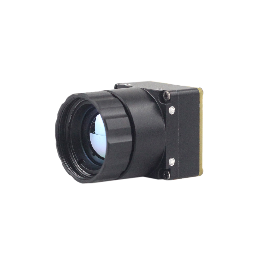
Purpleriver Mini 256x192 Uncooled LWIR Thermal Camera Module
الـ وحدة كاميرا حرارية مصغرة 256 غير مبردة بالأشعة تحت الحمراء ذات الموجة الطويلة adopts high-performance infrared detectors designed for clear thermal imaging and accurate temperature measurement. Engineered to capture infrared radiation and output uniform thermal imagery with integrated radiometry, its ultra-lightweight profile suits weight-critical deployments, including mine detection drones, search and rescue robots, and micro-UAV swarms.
- ⚙️ الدقة: 256 × 192 Active Pixels
- ⚙️ حجم البكسل: 12 μm High-Sensitivity Uncooled Microbolometer
- ✅ الحساسية الحرارية: ≤ 50 mK (NETD at f/1.0)
- ⚙️ قياس إشعاعي دقيق: Point, line, and area temperature tracking with accurate output
- ✅ Weight Profile: ≤ 12 g total mass (SWaP-optimized)
Comprehensive Specification Matrix
| معلمة المواصفة | Purpleriver Mini2 640x512 9mm | Purpleriver Mini 256x192 Core |
|---|---|---|
| معمارية الكاشف | مصفوفة مستوية بؤرية بمقياس ميكروبولومتر VOx غير مبرد | Uncooled LWIR Microbolometer FPA |
| دقة المصفوفة | 640 × 512 بكسل | 256 × 192 بكسل |
| تباعد البكسل | 12 ميكرومتر | 12 ميكرومتر |
| الحساسية الطيفية | 8 ميكرومتر إلى 14 ميكرومتر (LWIR) | 8 ميكرومتر إلى 14 ميكرومتر (LWIR) |
| حساسية NETD | ≤ 40 mK (f/1.0 at 300K) | ≤ 50 mK (f/1.0 at 300K) |
| Frame Output Rates | 25 هرتز / 30 هرتز / 50 هرتز | 25 Hz / 30 Hz |
| الواجهات الرقمية | MIPI CSI-2 (2-lane) / DVP / USB | MIPI CSI-2 (1 or 2-lane) / SPI |
| Control Command Bus | I2C / UART (Up to 921,600 bps) | I2C / UART |
| Radiometric Range | -20°C to +150°C (High Gain); up to +550°C (Low Gain) | -20°C to +150°C (Industrial Radiometry) |
| Measurement Accuracy | ±2°C or ±2% of reading | ±2°C or ±2% of reading |
| Standard Optic | 9mm (HFOV ≈ 48°) Athermalized | Integrated Wide-Angle Micro-Lens |
| Operational Power | < 900 mW (Continuous operation) | < 450 mW (Ultra-low power) |
| Module Mass | ≈ 18 g (Core) / 28 g (With 9mm Lens) | ≤ 12 g Total |
دليل التكامل خطوة بخطوة ودليل استكشاف الأخطاء وإصلاحها
Executing a reliable integration of a MIPI thermal camera module into an embedded carrier board requires following a structured hardware and software validation methodology.
Step 1: Hardware Rail Verification
Prior to powering the module, verify all voltage supply rails using an oscilloscope. Uncooled microbolometers are sensitive to power supply noise. Ensure the analog supply rail (VDD_ANA) exhibits less than 10 mVRMS ripple. High power ripple directly degrades the sensor's Noise Equivalent Temperature Difference (NETD), introducing horizontal banding across the raw image stream.
Step 2: Device Tree Compilation and Kernel Registration
Compile the Device Tree source overlay and load the driver kernel module into the Linux kernel space. Verify that the thermal sub-device acknowledges I2C commands using standard Linux utilities:
# Verify module acknowledges on I2C bus 1 at address 0x38
i2cdetect -y -r 1

# Inspect the kernel ring buffer for successful sub-device probing
dmesg | grep -i purpleriver
# Expected Output:
# [    4.120349] purpleriver_thermal 1-0038: Sensor probed successfully. Model: Mini2-640
# [    4.121110] purpleriver_thermal 1-0038: Subdev registered as /dev/v4l-subdev2
Step 3: Stream Capture Verification with V4L2 Utilities
Query the host video device node using v4l2-ctl to confirm supported pixel formats and negotiate the streaming format before launching higher-level vision applications:
# Query available pixel formats on host video node
v4l2-ctl --device=/dev/video0 --list-formats-ext

# Capture 100 test frames directly to file using direct MMAP DMA
v4l2-ctl --device=/dev/video0 \
         --set-fmt-video=width=640,height=512,pixelformat='Y16 ' \
         --stream-mmap --stream-count=100 \
         --stream-to=test_stream.raw
Step 4: Hardware-Accelerated GStreamer Pipeline Integration
To feed raw radiometric frames directly into hardware-accelerated processing pipelines, configure a zero-copy GStreamer pipeline. The pipeline below splits the incoming 16-bit raw data, directing one stream to hardware color-mapping for operator display and the other directly to an appsink for neural network inference:
gst-launch-1.0 v4l2src device=/dev/video0 ! \
    video/x-raw, format=GRAY16_LE, width=640, height=512, framerate=30/1 ! \
    tee name=thermal_tee \
    thermal_tee. ! queue leaky=1 ! \
        nvvideoconvert ! \
        video/x-raw(memory:NVMM), format=RGBA ! \
        nvdsosd ! nveglglessink sync=false \
    thermal_tee. ! queue leaky=1 ! \
        appsink name=radiometric_sink emit-signals=true max-buffers=1 drop=true
Diagnostic Matrix: Common Integration Pitfalls
| Reported Fault | Root Cause Analysis | Engineering Resolution |
|---|---|---|
| "MIPI CSI-2 FIFO Overflow / Packet CRC Error" | Differential length mismatch or clock-lane skew exceeding physical receiver margins. | Check trace routing; enforce intra-pair skew < 0.15mm. Ensure continuous ground plane under high-speed traces. |
| Driver fails to initialize: "LP-11 State Timeout" | Host receiver timed out waiting for module D-PHY to enter Low-Power standby state before High-Speed transmission. | Add a hardware reset hold time (trst > 15 ms) in DTS. Match clock mode (continuous vs. non-continuous) with module settings. |
| Frame displays severe fixed pattern noise (FPN) | Internal microbolometer temperature shifted during continuous operation without offset recalibration. | Trigger an internal shutter calibration via I2C command, or enable continuous shutterless compensation in the module's driver controls. |
فيديو توضيحي لنواة التصوير الحراري المصغرة 640×512
الأسئلة الشائعة المتعمقة حول التكامل الصناعي
Why choose a MIPI CSI-2 thermal camera module over USB or SPI interfaces for embedded vision?
SPI interfaces present bandwidth constraints. Standard single or quad SPI buses max out between 50 Mbps and 100 Mbps, making them incapable of transporting an uncompressed 640 × 512 14-bit stream at 30 Hz to 50 Hz without aggressive down-sampling or frame drops. In contrast, MIPI CSI-2 interfaces directly with the host processor's camera subsystem. Uncompressed raw radiometric data is delivered via hardware Direct Memory Access (DMA) into unified memory buffers with less than 2% CPU overhead and under 1.5 ms of glass-to-memory latency. This deterministic transfer is essential for mission-critical Edge AI target tracking and multi-sensor fusion.
How complex is embedded Linux driver bring-up for Purpleriver MIPI thermal modules?
The kernel driver registers as a standard v4l2_subdev, exposing interfaces for format configuration, framerate negotiation, and thermal parameter control via standard or extended V4L2 controls. Once the driver binds to the sensor, user-space utilities like media-ctl link the camera pad to the host SoC's capture interface. Reference Board Support Packages (BSPs), Device Tree source overlays, and pre-compiled GStreamer pipelines are available for platforms including NVIDIA Jetson (JetPack 5.x/6.x), Rockchip RK3588, and Raspberry Pi CM4. These resources help engineering teams complete driver integration in a few working days rather than months.
Are these MIPI thermal modules suitable for weight-sensitive drone and gimbal applications?
Operating power consumption is maintained below 900 mW for the Mini2 and under 450 mW for the Mini 256. This low power draw extends flight endurance and minimizes internal heat buildup. In sealed IP67 payloads, excess internal heat can cause microbolometer temperature drift and force repeated shutter recalibrations; these modules' low power dissipation helps preserve thermal stability. Additionally, their fine-pitch flexible printed circuit (FPC) connections can route cleanly through compact mechanical gimbal joints and slip rings without introducing mechanical drag on stabilization motors.
📚 المراجع والقراءات الإضافية
- ⚙️ المعيار الصناعي: High-speed interconnect and micro-coaxial cable assemblies for aerospace and robotic vision: Amphenol Corporation
- ⚙️ المعيار الصناعي: Molded chalcogenide infrared optical engineering and passive athermalization: لايت باث تكنولوجيز
- ⚙️ دليل ذو صلة: Multi-sensor design and dual-band optical alignment: CMOS Sensor Thermal Camera Module Integration Guide
- ⚙️ دليل ذو صلة: Advanced neural network deployment over localized infrared arrays: Промышленные мини-модули LWIR с ИИ (Industrial Mini LWIR Modules with AI)
- ⚙️ دليل ذو صلة: High-definition tactical electro-optics: 1280x1024 12μm Long Range Thermal Imaging Sight Scope