أفضل وحدة كاميرا حرارية 256x192 25 مم لمناظير DIY والطائرات بدون طيار: مستشعر IR طويل المدى فعال من حيث التكلفة
٣ يوليو ٢٠٢٦
وحدة الكاميرا الحرارية VOx بدقة 640x512: الدليل الشامل للذكاء الاصطناعي الطرفي والطائرات بدون طيار والبث المباشر
6 يوليو 2026
وحدة كاميرا تصوير حراري 90 مم مع ذكاء اصطناعي طرفي: دقة بعيدة المدى
في المراقبة البصرية بعيدة المدى، والمراقبة الصناعية، وحمولات الطائرات بدون طيار ذات الدرجة الدفاعية، يكون الطلب على اكتساب الأهداف بدقة عالية على مسافات ممتدة أمرًا بالغ الأهمية. تفشل العدسات ذات الزاوية الواسعة القياسية في توفير الدقة المكانية عند مدى الهدف ($IFOV$) المطلوبة للتعرف الإيجابي بعد بضع مئات من الأمتار. يوفر دمج وحدة كاميرا تصوير حراري 90 مم جسرًا لهذه الفجوة التشغيلية. من خلال إقران مقياس ميكروبولومتر غير مبرد عالي الدقة بمسافة بكسل 17 ميكرومتر أو 12 ميكرومتر مع مجموعة عدسات جرمانيوم بطول بؤري 90 مم، يمكن لمهندسي الأنظمة تحقيق مجالات رؤية ضيقة (FOV) محسّنة للمراقبة على مدى كيلومترات. عند تعزيزها بالذكاء الاصطناعي الطرفي المسرع بالأجهزة، تحول هذه الوحدات بيانات الأشعة تحت الحمراء طويلة الموجة (LWIR) الخام إلى معلومات استخباراتية قابلة للتنفيذ مباشرة على الطرف، مما يقلل من زمن الوصول ويزيل العبء الهائل لعرض النطاق الترددي لبث جداول الفيديو الحراري الخام عبر الوصلات اللاسلكية الهابطة.
تحتاج فرق الهندسة التي تدمج تقنيات الأشعة تحت الحمراء في مناظير تكتيكية مخصصة، أو منصات طائرات بدون طيار عالية الارتفاع، أو أنظمة أمن محيطي إلى أكثر من مكونات جاهزة من الدرجة الاستهلاكية. يحلل هذا المخطط المتطلبات الهيكلية والبصرية والإشعاعية لنوى الكاميرات الحرارية LWIR ذات 90 مم. نفحص كيف تتفاعل حساسية مستوى البكسل - المقاسة عبر فرق درجة الحرارة المكافئ للضوضاء (NETD) - مع ملفات النقل البصري لتحديد أقصى أداء حقيقي للمدى تحت التوهين الجوي في العالم الحقيقي. من خلال الفحوصات المعمارية التفصيلية، وأدلة دمج الأجهزة، وفحوصات المنتجات المقارنة، يعمل هذا الدليل التقني كمرجع نهائي لنشر حمولات LWIR ذكية واحترافية.
إليك الأمر: إذا كنت تبني أنظمة مخصصة للعمل في بيئات العالم الحقيقي المتقلبة، فلا يمكنك الاعتماد على الأرقام النظرية المثلى. تحتاج إلى التصميم لأسوأ تشتت جوي وتعظيم مزاياك البصرية من اليوم الأول. في الورشة، نشير إلى هذا على أنه هندسة للواقع الحراري، وليس لورقة البيانات.

جدول المحتويات
الفيزياء البصرية ومعاملات الدقة المكانية
1 البعد البؤري للعدسة مقابل حسابات IFOV
تتمثل الوظيفة الأساسية لعدسة ذات بعد بؤري 90 مم مقترنة بمستشعر الأشعة تحت الحمراء طويلة الموجة (LWIR) ويكيبيديا مقياس الميكروبولومتر في تقييد مجال الرؤية اللحظي ($IFOV$)، وبالتالي تعظيم الدقة المكانية على مسارات الهدف الطويلة. يمثل $IFOV$، وهو الإسقاط الزاوي لعنصر كاشف واحد (بكسل) في فضاء الجسم، مقياسًا أساسيًا. ويتم صياغته رياضيًا على النحو التالي:
$$IFOV = \frac{p}{f}$$
حيث $p$ هي المسافة الفيزيائية للبكسل في مصفوفة المستشعر (عادةً 12 ميكرومتر أو 17 ميكرومتر للنوى الصناعية القياسية) و $f$ هو البعد البؤري الفعال للمجموعة البصرية (90 مم).
بالنسبة لنواة مستشعر 12 ميكرومتر مدمجة مع عدسة 90 مم:
$$IFOV_{12\mu m} = \frac{12 \times 10^{-6}\text{ m}}{90 \times 10^{-3}\text{ m}} \approx 0.133\text{ mrad}$$
على العكس، بالنسبة لمستشعر 17 ميكرومتر القديم:
$$IFOV_{17\mu m} = \frac{17 \times 10^{-6}\text{ m}}{90 \times 10^{-3}\text{ m}} \approx 0.189\text{ mrad}$$
انظر، يؤدي تقليل مسافة البكسل من 17 ميكرومتر إلى 12 ميكرومتر إلى تقليل بنسبة 29.6% في الحجم الزاوي للبكسل. وهذا يُترجم مباشرة إلى معدل أخذ عينات أكثر كثافة للأهداف على بُعد مسافة. لوضع ذلك في مصطلحات ميدانية عملية، يتم حساب الدقة المكانية على مسافة 1,000 متر ($S_{1000}$) عبر:
$$S_{1000} = 1000\text{ m} \times IFOV$$
إليك ما يبدو عليه ذلك من حيث البصمة المادية:
- ✅ مستشعر 12 ميكرومتر @ عدسة 90 مم: $S_{1000} \approx 0.133\text{ m} = 13.3\text{ cm}$ بصمة مادية لكل بكسل. يمنحك هذا تفريدًا مكانيًا دقيقًا للغاية.
- ✅ مستشعر 17 ميكرومتر @ عدسة 90 مم: $S_{1000} \approx 0.189\text{ m} = 18.9\text{ cm}$ بصمة مادية لكل بكسل. لا يزال قابلاً للاستخدام، لكنه يفتقر إلى تعريف الحواف الدقيق لنظام 12 ميكرومتر.
عند التخطيط لتكوينات الكشف والتتبع والتعرف بعيدة المدى، تخضع الكثافة المكانية على الهدف لمعايير جونسون. للكشف القياسي عن الهدف (1.5 بكسل عبر البعد الحرج)، يجب أن يمتد الهدف البشري (المُصمم بعرض حرج 0.75 متر) على 1.5 بكسل على الأقل.
مع نظام أساسي 12 ميكرومتر، 90 مم، يتم اشتقاق أقصى مدى كشف ($R_{det}$) لهدف بشري في ظل ظروف نقل جوي مثالية ديناميكيًا من خلال:
$$R_{det} = \frac{\text{البعد الحرج للهدف}}{IFOV \times \text{البكسلات المطلوبة}} = \frac{0.75\text{ m}}{0.133 \times 10^{-3}\text{ rad} \times 1.5} \approx 3,759\text{ متر}$$
هذه الكثافة المكانية العالية تجعل مصفوفة البعد البؤري 90 مم أداة حاسمة لأنظمة تطويق الحدود المحيطية والبحث والإنقاذ. يمكن العثور على مزيد من التفاصيل حول اختيار المستشعر في دليلنا الشامل لوحدات مستشعر الكاميرا الحرارية.
2 أداء MTF في طيف 8-14 ميكرومتر
تملي دالة نقل التضمين (MTF) قدرة النظام على نقل التباين من المشهد البصري إلى سطح الكاشف عند ترددات مكانية متفاوتة، مقاسة بأزواج الخطوط لكل مليمتر ($\text{lp}/{\text{mm}}$). نظرًا لأن إشعاع الموجات تحت الحمراء طويلة الموجة (LWIR) يعمل ضمن النطاقات الطيفية $8\ \mu\text{m} \le \lambda \le 14\ \mu\text{m}$، فإن تردد القطع المكاني المحدود بالحيود يكون أقل بكثير من نظيره في بصريات الضوء المرئي، وتحكمه:
$$\xi_{cutoff} = \frac{1}{\lambda \cdot F\#}$$
عند التشغيل عند $F/1.25$ مع طول موجي وسطي $\lambda = 10\ \mu\text{m}$، يكون الحد الديناميكي الحراري المطلق لدالة النقل البصرية هو:
$$\xi_{cutoff} = \frac{1}{10 \times 10^{-3}\text{ mm} \times 1.25} = 80\text{ lp/mm}$$
تستخدم مجموعات العدسات القياسية من الجرمانيوم 90 مم المُهيأة لأنظمة مجال الرؤية المزدوج أو الزوم المستمر طلاءات مضادة للانعكاس (AR) وطلاءات صلبة كربونية/شبيهة بالألماس (DLC) لتحمل التدهور البيئي وتقليل انعكاسات فرينل الداخلية.
للحفاظ على أداء MTF على مستوى النظام أعلى من تباين $35\%$ عند تردد نايكويست لمستشعر الميكروبولوميتر 12 ميكرومتر ($\approx 41.6\text{ lp/mm}$)، يجب أن تصحح المجموعة البصرية الانحرافات الكروية واللونية واللابؤرية بشكل أصلي داخل مجموعتها متعددة العناصر من الجرمانيوم. تؤدي العدسات سيئة التصميم إلى تدهور MTF البصري دون حد نايكويست للمستشعر، مما يُدخل تمويهًا مكانيًا ويُخفض الحساسية الحرارية الفعالة لنظام الكاميرا المتكامل.
معماريات دمج الأجهزة الإلكترونية
1 توجيه جسر CMOS المتوازي الأصلي إلى MIPI CSI-2/USB 3.0
على مستوى السيليكون المادي، يتكون التغذية الرقمية الخام من الميكروبولومتر غير المبرد من ناقل CMOS متوازي عالي معدل البت ومنخفض الجهد (غالبًا بيانات رقمية خام 14 بت مقترنة بساعة البكسل `PCLK`، وصالح الخط `LVAL`، وومضات التحكم بصالح الإطار `FVAL`). تقوم النوى الحرارية عالية الأداء بتحويل هذا الناقل المتوازي محليًا إلى طوبولوجيات توصيل تسلسلي عالية الكثافة حديثة مثل واجهات MIPI CSI-2 أو USB 3.0/Type-C لدعم النطاق الديناميكي العالي ونقل البيانات عالي السرعة.
عند توجيه هذه الإشارات التفاضلية على لوحة مضيفة متعددة الطبقات، يجب على المهندسين تكوين معاوقات الهدف بدقة مع هذه التخطيطات المادية الصارمة:
- ⚙️ أزواج MIPI CSI-2 التفاضلية: يجب الحفاظ على معاوقة تفاضلية ثابتة مقدارها $100\ \Omega$ ($\pm 10\%$) لمنع مشكلات انعكاس الإرسال عالي التردد على مساري الساعة والبيانات.
- ⚙️ USB 3.0 SuperSpeed (TX/RX): يتطلب توجيه معاوقة تفاضلية مقدارها $90\ \Omega$.
- ⚙️ مراجع مستوى الأرضي: قم بتشغيل مستويات أرضية غير منقطعة مباشرة تحت جميع المسارات عالية السرعة لعزل الضوضاء الرقمية عن الواجهة الأمامية التناظرية الحساسة للميكروبولومتر.
Additionally, intra-pair skew must be limited to $<0.15\text{ mm}$ via symmetric trace routing and length snake-matching to prevent signal phase shifts on high-speed transitions. Developers can learn more about high-integrity board layups in our LWIR micro thermal camera module integration guide.
For integration with automated positioning platforms and multi-sensor stabilization gimbals, شركة Shenzhen ChiYi Electronics Co., Ltd. provides specialized, low-latency interface converters. These components bridge industrial LWIR parallel buses to digital video outputs like HD-SDI, LVDS, or HDMI, preserving signal integrity across extended harness routings.
2.2 SDK-level interfaces for Embedded SBCs
To ingest raw 14-bit radiometric datasets into a single-board computer (SBC) like a Raspberry Pi 4/5, NVIDIA Jetson Orin Nano, or custom ARM/FPGA processing blocks, developers need to leverage the thermal core SDK. The integration pipeline executes over standard interface buses, extracting the payload directly to raw memory buffers. The process begins by instantiating raw UVC stream listeners using a backend like `libuvc` or standard kernel interfaces:
#include <iostream>
#include <libuvc/libuvc.h>

// Callback signature for processing incoming raw LWIR frames
void frame_callback(uvc_frame_t *frame, void *ptr) {
    if (frame->data_format != UVC_FRAME_FORMAT_Y16) {
        std::cerr << "Error: Incoming frame format is not 16-bit Raw Radiometric." << std::endl;
        return;
    }

    // Cast the payload data pointer to unsigned 16-bit array
    uint16_t *raw_data = static_cast<uint16_t*>(frame->data);
    int width = frame->width;
    int height = frame->height;

    // Read central frame pixel for core temperature monitoring
    int center_pixel_index = (height / 2) * width + (width / 2);
    uint16_t raw_val = raw_data[center_pixel_index];

    // Convert Kelvin hundredths representation to Celsius:
    // Temp (K) = Raw_Val / 100.0f -> Celsius = Temp (K) - 273.15f
    float temperature_celsius = (static_cast<float>(raw_val) / 100.0f) - 273.15f;

    std::printf("Center Pixel Raw: %u | Temperature: %.2f °C\n", raw_val, temperature_celsius);
}
This raw pipeline bypasses standard video encoders, preserving target temperature calculations down to $\pm 2^\circ\text{C}$ or $2\%$ accuracy per pixel location.
إطلاق العنان للذكاء الاصطناعي الطرفي: الاستدلال الفوري على المستشعر
3.1 FPGA and NPU hardware acceleration layers
On-sensor core processing relies on an FPGA/ASIC coprocessor running parallelized pipelines for real-time spatial correction, Non-Uniformity Correction (NUC), and Bad Pixel Replacement (BPR). Applying these correction arrays before deep neural network inference prevents dead pixels and column drift from causing false positives in target detection.
For models running Yolov8 or MobileNet-SSD targets on local Edge NPUs, the 14-bit analytical radiometric stream is parallel-processed. One branch scales the thermal dynamic range using an adaptive histogram projection algorithm down to an INT8 tensor space suitable for neural network layers. The quantization phase maps microkelvin variance to robust physical features, enabling autonomous systems to identify personnel, structures, and machinery in low-visibility or highly congested environments.
To explore native AI accelerators inside compact LWIR setups, see our Edge AI enhanced LWIR module integration guide.
3.2 Temperature Measurement & Radiometric Data Structures
True radiometric monitoring systems output raw pixel data that corresponds directly to actual physical temperature values. Each pixel value represents a highly calibrated sensor capture of the radiant energy emitted by the target object. To maintain reading accuracy across varying ambient conditions, the internal calibration algorithm calculates compensation factors based on key physical properties. In practice, our workflow uses these parameters:
- ⚙️ Target Emissivity ($E$): Dictates the emission efficiency of the target material's surface (calibrated from 0.01 to 1.00).
- ⚙️ Atmospheric Distance ($D$): Compensates for path attenuation losses along the 90mm optical line-of-sight.
- ⚙️ Ambient Temperature ($T_{amb}$): Compensates for reflected ambient radiation entering the optical path.
These variables are adjusted dynamically in software via the SDK control registry. Writing updated values to the registers adapts the internal radiometric calculation based on the distance to the target and the local atmospheric conditions.
مراجعة مقارنة لوحدات نوى LWIR الصناعية
To guide procurement and engineering teams, the detailed comparison below lists the technical parameters of currently available uncooled LWIR core systems, categorized by pixel density, output formats, and range capabilities.
4.1 Direct product parameters & datasheet matching
| Model Specifications | Uncooled LWIR Mini 256*192 Core | Uncooled LWIR USB Mini 640*512 Core |
|---|---|---|
| Product Target Image | 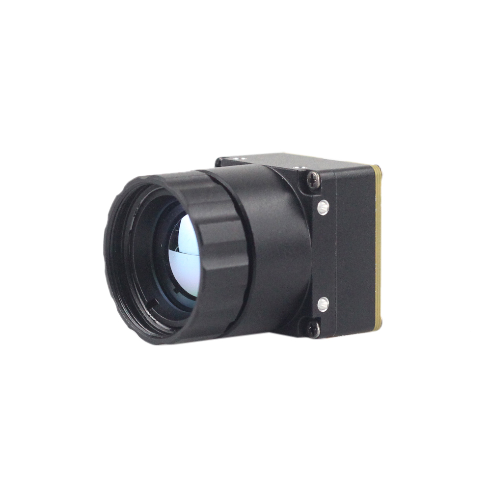 |
 |
| دقة الكاشف | 256 x 192 (Ultra-Compact Form Factor) | 640 x 512 / 640 x 480 (High-Resolution Core) |
| تباعد البكسل | 12 µm | 12 µm |
| النطاق الطيفي | 8 µm to 14 µm (LWIR) | 8 µm to 14 µm (LWIR) |
| الحساسية الحرارية (NETD) | ≤ 50 mK (Ultra-clear thermal output) | ≤ 40 mK (Sharp and crisp image presentation) |
| Available Lenses (Focal Length) | Integrated wide/mid fixed lenses | 5 / 9 / 13 / 18 / 35 / 50 / 75 / 100 / 150mm configurations |
| Weight & Dimensions | Ultra-lightweight miniature design | 21mm x 21mm base mini-size, ultra-low cost |
| Primary Applications | Detecting mines, compact UAVs, local temperature mapping | Long-range drones, perimeter tracking, thermal sights |
Showcasing: Uncooled LWIR Mini 256*192 Thermal Imaging Camera Module Similar To DJI For Detecting Mines
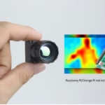
The Mini 256 Uncooled LWIR thermal Camera Module adopts high-performance infrared detectors for ultra-clear thermal imaging and accurate temperature measurement. It captures infrared radiation and outputs a uniform thermal image with radiometry. This brings micro-class accuracy to search-and-rescue, micro UAV deployment, and specialized structural hazard mitigation missions.
Its lightweight structure makes it ideal for close-range and medium-range remote sensing work where every gram counts. Offering clean integration on single-board computers, it delivers raw temperature fields directly over modern digital buses.
Showcasing: Uncooled LWIR USB Mini 640*512 Thermal Imaging Camera Core Module For Drones Similar To DJI
Design teams requiring clean performance over long detection channels rely on high-resolution setups. The Mini uncooled infrared thermal imaging module features in sharp and crisp image presentation, compact size and low cost. Featuring a mini-size of 21mm*21mm, and with lens focal lengths spanning 5/9/13/18/35/50/75/100/150mm and 640*480 resolution optional, it ensures stable performance and strong environmental adaptability.
When used with telephoto and zoom configurations up to 90mm or 150mm, it delivers clear physical signatures of targets several kilometers away. This level of resolution is crucial for automated perimeter defense, critical infrastructure protection, and drone-based search operations.
أطر الدمج: الطائرات بدون طيار، المناظير التكتيكية، والروبوتات المستقلة
Implementing robust thermal imaging capabilities within real-world payloads requires careful balancing of mechanical, thermal, and optical considerations to protect the core-level electronics.
5.1 Drone payload SWaP considerations
For Size, Weight, and Power (SWaP) constraints on unmanned aerial vehicles (UAVs), integrating a 90mm focal length lens introduces a weight offset that shifts the sensor's center of gravity forward.
- ✅ Weight Offset: A 90mm telephoto germanium lens can weigh between $180\text{ g}$ and $350\text{ g}$, compared to a lightweight $15\text{ g}$ ultra-microbolometer core.
- ✅ Gimbal Balancing: Placing the core-sensor assembly behind a heavy lens shift moves the target balance forward. The physical center of gravity on custom dual-axis brushless gimbals must be manually trim-balanced along the pitch axes. This ensures the gimbal motors don't overheat or degrade control loop integrity during high-frequency wind corrections.
Peak motor torque requirements ($T_m$) are calculated based on predicted wind loads and operational angular accelerations:
$$T_m = I_{axis} \cdot \alpha_{target}$$
where $I_{axis}$ is the combined moment of inertia of the 90mm lens and core structure, and $\alpha_{target}$ is the targeted angular response speed. Ensuring the gimbal system has adequate holding torque prevents tracking slippage in turbulent flight conditions.
Additionally, a 90mm core-system drawing up to $1.5\text{W}$ at peak performance (typically during automated calibration shutter cycles) must be powered via shielded DC-DC buck step-down converters. This prevents high-frequency electromagnetic interference (EMI) from degrading the UAV's GPS, compass, and telemetry communications.
5.2 Scope & Weapon-Sight ruggedized optomechanics
To deploy 90mm uncooled thermal assemblies in tactical sighting systems, the mountings and internal electronics must withstand high, sudden mechanical forces:
- ⚙️ Shock & Vibe Isolation: Sighting assemblies can experience impulse accelerations exceeding $1,000\text{ G}$ over sub-millisecond durations during recoil. Sensor cores must be shock-isolated within the main CNC-milled chassis using structural fluoro-silicone dampers. This protects both the ceramic microbolometer package glass seal and the optical sub-assembly.
- ⚙️ Atmospheric & Environmental Sealing: Sighting scopes must maintain an inert internal environment across rapid temperature and pressure changes. Housings should be nitrogen-purged and sealed with dual Viton O-rings to an IP67 rating. This prevents moisture from condensing on the internal optical surfaces of the germanium lens elements.
- ⚙️ Thermal Isolation & Uniformity: Changes in barrel temperature can transfer heat to the scope enclosure, creating internal thermal gradients. Isolating the infrared core from the mounting rings using Delrin or G10 fiberglass thermal isolation rings helps maintain spatial temperature uniformity across the detector array. This minimizes calibration drift and ensures accurate target detection over extended operations.
الأسئلة الشائعة المتعمقة
Can I stream real-time, high-resolution thermal data from a 90mm module to a Raspberry Pi or Arduino?
In contrast, 8-bit or 32-bit microcontrollers like Arduino Uno, ESP32, or STM32 lack the memory bus bandwidth and processing capacity required for real-time high-resolution video streams. A $640\times512$ frame at 16 bits per pixel requires $655,360\text{ bytes}$ of physical RAM per frame buffer, which exceeds the entire RAM capacity of standard microcontrollers. For lightweight microcontroller integrations, a downsampled low-rate SPI or serial telemetry stream can be used to capture raw temperature readings at lower frame rates (typically $\le 2\text{ fps}$). Alternatively, high-performance applications should leverage dedicated embedded processors to stream full-frame, high-resolution thermal video.
How does a 90mm thermal imaging module perform for custom DIY scopes, UAV integration, and vehicle-mounted projects?
$$HFOV = 2 \cdot \arctan\left(\frac{640 \times 12 \times 10^{-6}\text{ m}}{2 \times 90 \times 10^{-3}\text{ m}}\right) \approx 4.88^\circ$$
This narrow field of view concentrates the spatial resolution of the sensor over a highly focused area, enabling long-range target classification at distances that standard wide-angle cores (e.g., 9mm or 13mm models) cannot resolve. For drone and vehicle mounts, this high optical magnification allows operators to maintain a safe standoff distance while capturing clear, detailed thermal images. However, the narrower field of view also increases sensitivity to mechanical vibrations. Integrating these systems on moving platforms typically requires active stabilization, such as a high-frequency brushless gimbal, or electronic image stabilization (EIS) algorithms on custom tactical scopes to maintain a steady image and prevent target tracking loss.
Why choose a professional Edge AI thermal core over a salvaged automotive or cheap DIY sensor?
With a professional Edge AI thermal core, developers gain access to comprehensive SDKs, open firmware standards, API configurations, and calibrated radiometric data ($Kelvin = LSB / 100$) directly over standard digital connections. Modern cores also feature on-board hardware accelerators for intelligence pipelines, allowing developers to execute tracking, object detection, and temperature-anomaly triggering directly on the core without needing heavy external processing assemblies.
📚 References & Further Reading
- المعيار الصناعي: ويكيبيديا مقياس الميكروبولومتر
- Manufacturer Portal: شركة Shenzhen ChiYi Electronics Co., Ltd.
- Integration Guides: