








640x512 VOx Thermal Camera Module: The Ultimate Guide for Edge AI, Drones & Live Streaming
2026年7月6日
Best MIPI Thermal Camera Module for Raspberry Pi & Drone Integration: OEM/ODM Pricing Guide
2026年7月7日
SPI Thermal Camera Module: High-Res LWIR Cores for ESP32 & Raspberry Pi Integration
For embedded systems engineers, drone developers, and industrial IoT architects, capturing high-resolution thermal imaging within tight structural and computational budgets is a significant hardware challenge. Standard camera interfaces like MIPI-CSI often demand excessive processing overhead, while standard USB-based thermal cameras can overwhelm low-power microcontrollers due to driver overhead and physical space requirements. An spi thermal camera module bridged directly to an uncooled Long-Wave Infrared (LWIR) microbolometer core offers an elegant solution. By utilizing the Serial Peripheral Interface (SPI) for registry control and pixel data transport, hardware designers can bypass the driver stack of bulky operating systems. This enables microcontrollers like the ESP32-S3 and single-board computers like the Raspberry Pi to capture real-time, radiometric thermal frames directly at the register level.
Integrating these high-resolution LWIR cores into lightweight drone payloads, compact monitoring stations, or industrial IoT enclosures requires a deep understanding of hardware interfaces. This guide explores the mechanical, electronic, and software protocols necessary to interface high-performance uncooled LWIR sensor cores (ranging from ultra-compact 256x192 modules to high-definition 640x512 arrays) with edge processing platforms. We will analyze the physics of uncooled microbolometers, detailing how to utilize SPI clocks, chip-select lines, and DMA (Direct Memory Access) buffers to stream high-density thermal matrices without dropping frames.
Look, when you are designing for the field, every millimeter and milliwatt counts. Standard off-the-shelf thermal imagers packaged in heavy aluminum enclosures just won't cut it when you are building a custom drone gimbal or a sealed hazardous-gas monitoring enclosure. Here's the deal: by stripping away the consumer-grade casing and going straight for an uncooled LWIR core with a bare SPI interface, you gain absolute control over the physical and electrical design. You program the registers yourself, route the power lines to match your system's LDO profiles, and process the raw 14-bit thermal arrays exactly how your application demands, without any middleman software slowing down your pipeline.
In the shop, we see a lot of developers get tripped up by trying to treat these high-end thermal cores like simple SPI temperature sensors or basic breakout boards. These are highly sensitive, scientific-grade instruments packaged into incredibly compact layouts. You can't just slap down some breadboard jumper wires and expect a clean 25 Hz frame rate. You need to respect the high-speed signal integrity, handle the raw sensor calibration matrices with specialized algorithms, and manage your memory buffers with precision. This guide is going to walk you through exactly how to do that, from the low-level silicon physics up to the clean C code running on your target processors.
Table of Contents
- 👉 2. Foundational Physics: LWIR & Microbolometers
- 👉 3. SPI Hardware Interface & Protocol Specifications
- 👉 4. Microcontroller Integration: ESP32 & Raspberry Pi
- 👉 5. Industrial Hardware Profiles & Technical Node Comparison
- 👉 6. Embedded Edge Application Implementations
- 👉 7. Comprehensive Technical FAQ Deep-Dive
2. Foundational Physics: LWIR & Microbolometers
Uncooled Microbolometer Technology
At the center of any modern high-performance thermal camera lies an uncooled microbolometer. Unlike older generation infrared sensors that required cryogenic cooling (such as Stirling cycle coolers), an uncooled microbolometer sensor array operates at ambient temperatures. This makes it ideal for size, weight, and power (SWaP) constrained applications like drone payloads and portable devices.
The sensor’s focal plane array (FPA) consists of microscopic elements layout across a silicon substrate. Each individual pixel acts as an infrared-absorbing membrane suspended over a Read-Out Integrated Circuit (ROIC). As long-wave infrared radiation (8µm to 14µm) passes through the optical system—typically made of high-transmittance Germanium—it strikes these suspended membranes. The absorption of IR radiation elevates the membrane's physical temperature. These structures are made with specialized materials like Vanadium Oxide (VOx) or Amorphous Silicon (α-Si), which feature a high Temperature Coefficient of Resistance (TCR). Even minor thermal flux shifts the electrical resistance of the microbolometer element. This resistance change is measured by the ROIC beneath the pixel matrix. The ROIC converts this analog signal into digitized voltage values, outputting them as raw digital counts for SPI or parallel data busses.
Radiometric Performance: Precision in Every Pixel
Industrial-grade LWIR cores, like those found in KUYANG thermal architectures, differ from basic thermopile arrays through their radiometric capability. A standard thermal imager is illustrative; it displays relative differences in temperature through pseudocolor pallets without measuring exact targets. In contrast, a fully radiometric thermal camera core calibrates every pixel to compute precise, absolute temperature readings in Kelvin, Celsius, or Fahrenheit.
Achieving accurate radiometric performance requires real-time correction algorithms executed directly on the module's onboard FPGA or DSP. In the field, raw uncooled sensors are notoriously susceptible to environmental drift and noise. To combat this, the onboard processor executes three critical correction steps before the SPI database ever sees the frame:
⚙️ Non-Uniformity Correction (NUC): Raw microbolometer output suffers from spatial drift due to tiny manufacturing variances between pixels. To smooth this out, a mechanical shutter periodically closes over the sensor, establishing a perfectly uniform thermal reference baseline to recalculate gain offset matrices.
⚙️ Bad Pixel Replacement (BPR): Individual pixels in the micro-array can die or become hyper-active over time. The processing core constantly monitors for these anomalies, instantly flagging dead pixels and interpolating their digital values using adjacent operational pixels to maintain a seamless visual field.
⚙️ Gain and Offset Calibration: As the overall camera housing heats up during operation, the baseline resistance of the focal plane shifts. Real-time thermal algorithms continuously monitor internal temperature diodes, scaling the raw ADC output to ensure that a 100°C target reads exactly the same whether the camera is in a freezing field or a hot engine room.
Integrating digital radiometric arrays into microcontrollers allows edge devices to perform advanced functions. Devices can run localized analytics, manage alarms for anomaly detection, and isolate critical zones in target environments—all without demanding high-end processing from external cloud servers.
3. SPI Hardware Interface & Protocol Specifications
Mastering the Serial Peripheral Interface (SPI) in Thermal Imaging
To output rapid frames of raw thermal matrices, designers often use SPI due to its synchronous, full-duplex nature and low driver overhead. While standard camera architectures operate over complex MIPI-CSI physical layers, SPI simplifies connections onto basic pins. The host master, such as an ESP32 or Raspberry Pi, drives the Serial Clock (SCLK) to synchronize shifting data bits. The MOSI (Master Out Slave In) line writes configuration commands, sets exposure windows, adjusts NUC commands, and controls gain settings of the thermal processor. Meanwhile, the MISO (Master In Slave Out) line streams raw pixel arrays and register-level radiometric matrices back to the host microcontroller. Lastly, the Chip Select (CS) line enables the target SPI module, where transitioning from high to low initiates the frame sync phase.
SPI Frame Framing & Timing Constraints
To prevent frame tearing or buffer overflows when transfer rates reach millions of pixels per second, understanding timing parameters is essential. Most professional Wikipedia Microbolometer SPI cores operate in SPI Mode 3 (CPOL=1, CPHA=1), where SCLK idles high, and data is latched on the rising clock edge.
Every full thermal image is structured with explicit package boundaries. Specifically, the data frame packet consists of a header block containing the Frame ID and ambient temperature, followed by the raw 14-bit temperature values, and concludes with a CRC-16 checksum line. The active frame rate determines the minimum clock frequency required. For instance, streaming a 256x192 resolution video core at 25 frames per second using 14-bit raw transmission requires approximately 19.66 Mbps of SPI bandwidth. This throughput is within the operating range of an ESP32 or Raspberry Pi. However, scaling to a 640x512 array at 25 frames per second increases the bandwidth demand to approximately 131.07 Mbps. At this volume, alternative bus topologies or high-speed Parallel architectures are required. These formats are supported by advanced uncooled LWIR cores to provide stable high-definition thermal streams without structural bottlenecks.
4. Microcontroller Integration: ESP32 & Raspberry Pi
ESP32-S3 Hardware Pipeline Options
To interface a high-resolution uncooled thermal module with an ESP32-S3 microcontroller, designers must optimize the direct memory access (DMA) bus structures. The ESP32's dual cores allow for a split-task design: Core 0 handles hardware SPI-DMA frame assembly, while Core 1 executes thermal rendering and sensor analysis.
A Ping-Pong buffering strategy utilizing dual DMA buffers is highly effective. Initialize two distinct RAM buffers in the ESP32's internal SRAM. While the hardware DMA engine populates the "Ping" buffer with incoming MISO bytes, Core 1 reads raw thermal frame data from the "Pong" buffer to calculate temperatures and draw frames. To prevent transmission delay, configure the ESP32 SPI host up to 26 MHz or 40 MHz. Below is a low-level C code snippet for ESP32 SPI initialization:
#include "driver/spi_master.h"
#include "esp_log.h"

#define PIN_NUM_MISO 13
#define PIN_NUM_MOSI 11
#define PIN_NUM_CLK  12
#define PIN_NUM_CS   10

spi_device_handle_t spi_thermal_handle;

void init_spi_thermal_core() {
    spi_bus_config_t buscfg = {
        .miso_io_num = PIN_NUM_MISO,
        .mosi_io_num = PIN_NUM_MOSI,
        .sclk_io_num = PIN_NUM_CLK,
        .quadwp_io_num = -1,
        .quadhd_io_num = -1,
        .max_transfer_sz = 256 * 192 * 2 // Dual byte representation of 256x192
    };

    spi_device_interface_config_t devcfg = {
        .clock_speed_hz = 20 * 1000 * 1000, // 20 MHz SCLK
        .mode = 3,                          // SPI mode 3 (CPOL=1, CPHA=1)
        .spics_io_num = PIN_NUM_CS,
        .queue_size = 7,                    // Queue deep transfers
        .flags = SPI_DEVICE_NO_DUMMY
    };

    esp_err_t ret = spi_bus_initialize(SPI2_HOST, &buscfg, SPI_DMA_CH_AUTO);
    if (ret == ESP_OK) {
         ret = spi_bus_add_device(SPI2_HOST, &devcfg, &spi_thermal_handle);
         ESP_LOGI("SPI_INIT", "Thermal Core SPI Engine Configured successfully.");
    }
}
Raspberry Pi SBC Pipeline (Linux OS Driver Interfacing)
On Linux Single Board Computers like the Raspberry Pi Zero 2W or Raspberry Pi 4/5, the driver layer uses either `/dev/spidev0.0` or a custom GPIO kernel module. Because vanilla Linux index processes can introduce latency, scheduling anomalies can cause dropped frames. This issue can be resolved with several key techniques. First, expand the default SPI kernel buffer limit (typically limited to 4096 bytes) by appending configuration code details to the `/boot/firmware/cmdline.txt` file, setting `spidev.bufsiz=131072`. Second, prioritize processing threads using `pthread_setschedparam` within diagnostic scripts to prioritize thermal collection processing as real-time system executions (FIFO priority scheduling). Finally, for high-speed applications, utilize C++ APIs alongside low-level libraries like `libgpiod` to bypass user-space latency. This allows Raspberry Pi modules to ingest 256x192 thermal inputs at 25 Hz while maintaining low CPU utilization.
5. Industrial Hardware Profiles & Technical Node Comparison
Developing high-efficiency thermal payloads requires evaluating physical form factor constraints alongside electronic parameters. Miniature high-resolution uncooled microbolometers combine compact footprints with flexible optical configurations. The product profiles below outline different integration options: from ultra-light thermal camera modules designed for UAV mine-detection payloads, to high-resolution uncooled cores optimized for surveillance, industrial equipment, and advanced imaging systems.
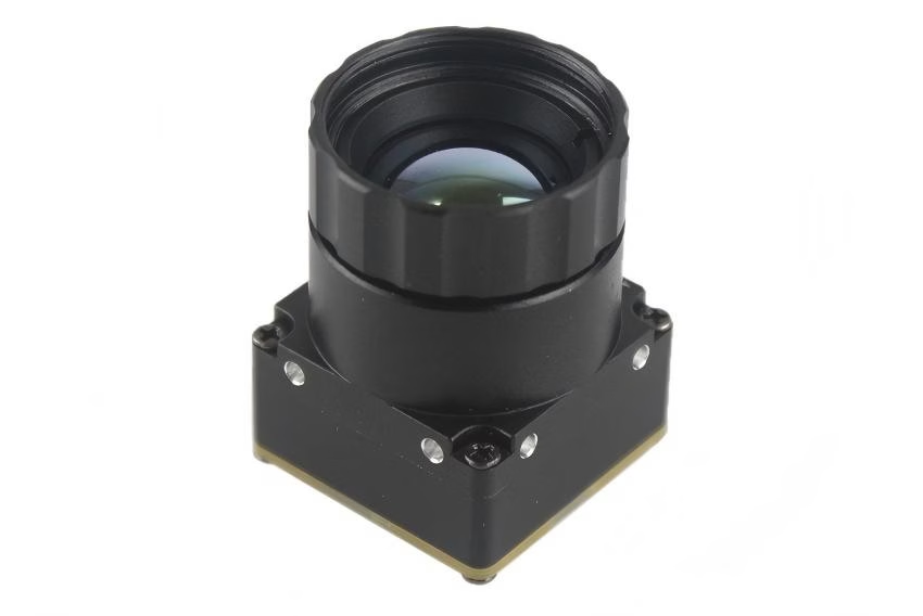
Product Profile 1: LWIR Mini 640 x 512 Thermal Imaging Camera Core Module
Mini uncooled infrared thermal imaging module features in sharp and crisp image presentation, compact size and low cost. Mini-Size of 21mm*21mm, 5/9/13/18/35/50/75/100/150mm, 640*480 resolution optional, stable performance and strong environmental adaptability.
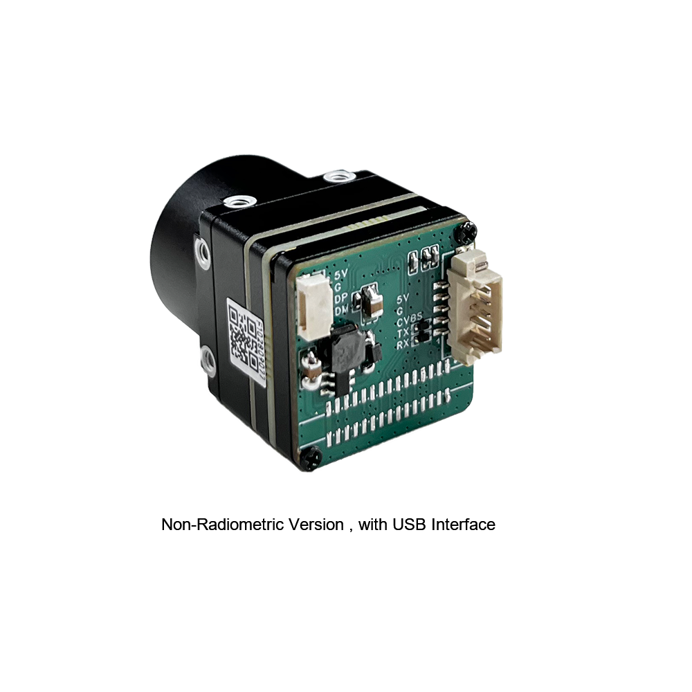
This uncooled LWIR USB Mini 640*512 thermal imaging camera core module is specifically optimized for drones and UAV platforms, matching DJI class thermal payload integrations. Its ultra-lightweight form factor simplifies layout configurations on brushless gimbals, while the high resolution guarantees maximum detail for inspection operations.

View Product Details & Pricing ➔
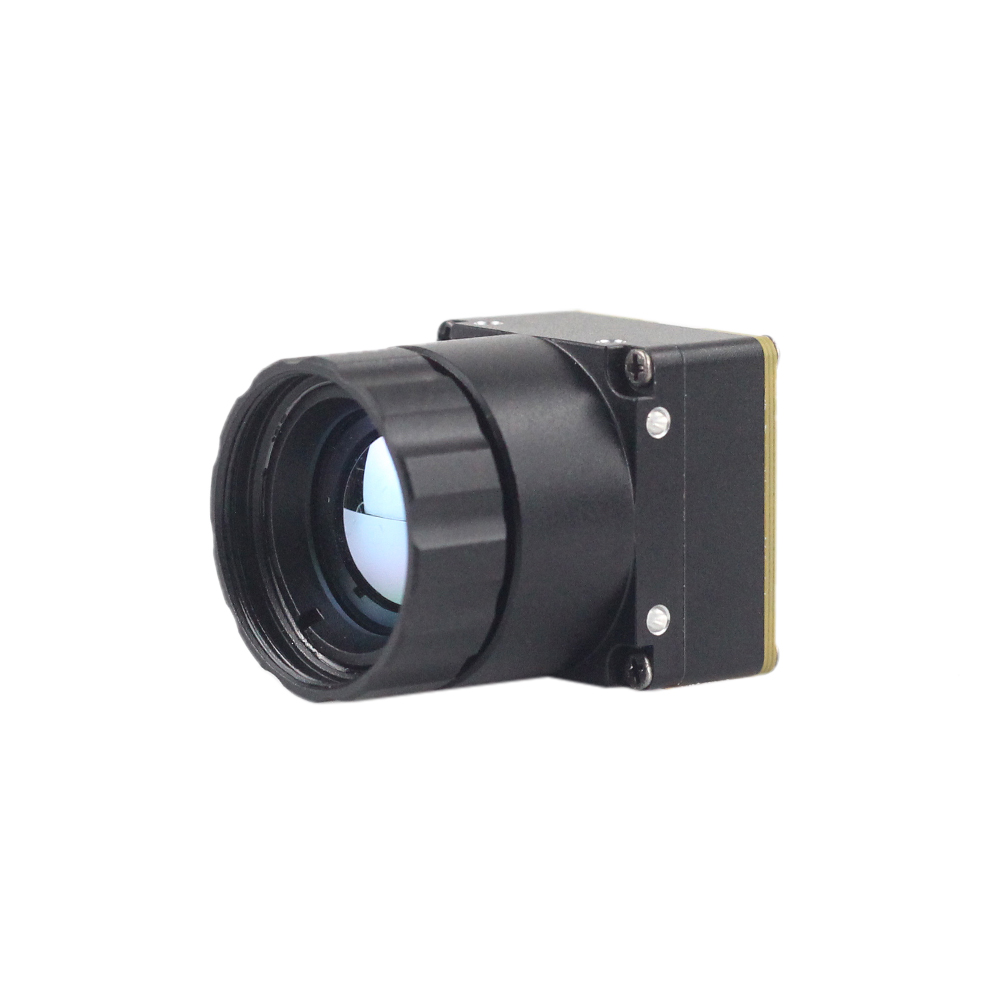
Product Profile 2: LWIR Mini 256 x 192 Thermal Imaging Camera Core Module
Mini 256 Uncooled LWIR thermal Camera Module adopts high-performance infrared detectors for ultra-clear thermal imaging and accurate temperature measurement. It captures infrared radiation and outputs a uniform thermal image with radiometry.
The core features high adaptability for specialized defense and industrial detection configurations, including detecting buried mines. Powered by professional radiometric calibrations, it transforms compact UAV payloads into automated anomaly mapping instruments.
View Product Details & Pricing ➔
Technical Node Comparison Table
The following dynamic hardware parameters compare these LWIR thermal camera modules side-by-side:
| Technical Parameter | LWIR Mini 256 x 192 Module | LWIR Mini 640 x 512 Module |
|---|---|---|
| Sensor Architecture | Uncooled Vanadium Oxide (VOx) | Uncooled Vanadium Oxide (VOx) |
| Sensing Resolution | 256 x 192 Pixels (49,152 points) | 640 x 512 Pixels (327,680 points) [640*480 optional] |
| Pixel Pitch | 12µm (Optimized performance) | 12µm (High spatial resolution) |
| Spectral Range | 8µm to 14µm (LWIR Band) | 8µm to 14µm (LWIR Band) |
| NETD (Thermal Sensitivity) | < 50mK (at 25°C, F/1.0) | < 40mK (at 25°C, F/1.0) |
| Physical Dimensions | 21mm x 21mm x 20mm | 21mm x 21mm (Mini-Size) |
| Available Lenses | 5/9/13/18/35mm manual/auto focal | 5/9/13/18/35/50/75/100/150mm selection |
| Digital Interfaces | SPI, USB, Parallel (Multi-Platform) | USB, SPI, Parallel, LVDS, BT.656 |
| Input Power Budget | < 0.8W at peak throughput | < 1.2W at peak processing |
| Typical Application | UAV payload, Mine detection, SWaP IoT | High-res drone monitoring, Mapping, Surveillance |
6. Embedded Edge Application Implementations
UAV & VTX Integrated Mine Detection Arrays
In small unmanned aerial vehicles (UAVs), payload mass and volume are critical factors. Traditional radiometric thermal imagers, packaged in heavy aluminum enclosures, can severely degrade flight times. Using bare uncooled 21mm x 21mm modules, like the LWIR Mini 256, allows designers to interface the thermal core directly with low-latency Video Transmitters (VTX) or flight control boards. The uncooled core captures sharp thermal gradients of hidden structures, surface anomalies, and metallic housings on the ground.
By offloading the image processing pipeline to an onboard single-board computer, the system can parse incoming frame matrices in real time. Dynamic filters identify buried mines with high thermal conductivity relative to surrounding loose soil. This allows automated targeting systems to log anomalous thermal coordinates directly into the flight controller's autopilot software. For a look at how thermal video captures dynamic fields in real-time tracking, check out our demonstration of phone thermal camera real shot video applications.
Industrial Smart Enclosures and AI Diagnostics
Within electrical grid substations and manufacturing hubs, physical space inside distribution panels can be extremely limited. Traditional hand-held tools cannot provide continuous, automated thermal monitoring of internal components. Integrating compact SPI thermal modules into these panels enables a decentralized diagnostic architecture.
Automated thermal monitoring algorithms continuously track the operating temperatures of critical connections, looking for the early warning signs of high electrical resistance before a fault occurs. A local microcontroller processes the temperature matrix directly. If a localized pixel exceeds safe thresholds, the system can trigger isolator units or send alert packets over low-power regional networks like LoRa or industrial Ethernet. Localized analysis allows the system to differentiate between a developing component failure and temporary, external heat sources, reducing false alarms and preventing unnecessary downtime. Explore how this relates to consumer and maintenance settings in our comprehensive article on smartphone thermal camera integration in daily life.

7. Comprehensive Technical FAQ Deep-Dive
Can I stream high-resolution, real-time thermal video from an SPI thermal camera module to an ESP32 or Raspberry Pi?
Are these compact SPI-compatible modules suitable for drone integration and VTX setups?
Do these thermal modules support accurate, real-time radiometric temperature measurements?
How should I determine the optimal lens focal length (e.g., 5mm, 9mm, or 13mm) for my integration?
What precautions are necessary to prevent microbolometer sensor degradation during integration?
📚 References & Further Reading
- Industry Standard: Wikipedia Microbolometer Technology Foundations
- Manufacturing Partner: KUYANG Optoelectronic Solutions Portal
- Related Guide: Smartphone Thermal Camera: Bringing Temperature Visualization Into Daily Life
- Direct Account and SDK Access: Developer Central Support & Account Portal





