Top Pro-Grade Thermal Imaging Sensor Module: AI-Enhanced LWIR Solutions for Drones & DIY Tech
2026年6月23日
High-Resolution Thermal Imaging Camera Module for Raspberry Pi: The Ultimate Edge AI Integration Guide
2026年6月24日
Best Thermal Imaging Module for Drone Integration: Edge AI & LWIR Guide
If you're building commercial-grade drones today, you already know the drill: payload efficiency, thermal resolution, and real-time processing are make-or-break variables. As aerial inspection, border surveillance, and search-and-rescue (SAR) missions move toward fully autonomous operations, picking your core thermal imaging module for drone architectures is the single most important hardware decision you'll make. This guide gets down into the weeds of the optical, electrical, and computational tradeoffs you have to make when integrating Long-Wave Infrared (LWIR) cores into multirotor, fixed-wing, and FPV platforms.
Here's the deal: by balancing Size, Weight, Power, and Cost (SWaP-C) limits against fast hardware interfaces like MIPI CSI-2 and USB, you can get video latency down to near-zero. On the bench, we have to look past the marketing spec sheets. We must evaluate the real-world performance of vanadium oxide (VOx) microbolometer cores, optical materials, radiometric accuracy, and how to run low-latency Edge AI pipelines directly on your payload hardware.
Table of Contents
- 👉 1. Introduction: The Evolution of Aerial LWIR Sensing
- 👉 2. SWaP-C Decoded: Engineering Metrics for Drone Payloads
- 👉 3. Interface Architectures: Choosing Between MIPI CSI-2 and USB Cores
- 👉 4. LWIR Optical Subsystems: Calculating FOV & DRI for Aerial Scenarios
- 👉 5. Edge AI Processing on the Payload: On-Board Machine Vision Algorithms
- 👉 6. Comprehensive Product Specifications & Interactive Matrix
- 👉 7. Step-by-Step OEM Integration: Hardening, Power, & Thermal Radiometry
- 👉 8. Industrial Integration FAQ: Custom FPV, Edge Inference, & Flight Dynamics
1. Introduction: The Evolution of Aerial LWIR Sensing
In the early days of aerial thermography, thermal cameras for unmanned aircraft were massive, power-hungry pieces of military reconnaissance gear. Those legacy systems required cryogenically cooled detectors. They offered unmatched thermal sensitivity, sure, but they were way too expensive and heavy to fit on a commercial multirotor. Over the last ten years, the shift to uncooled vanadium oxide (VOx) and amorphous silicon (a-Si) microbolometer sensors completely changed the game. These modern, uncooled sensors work natively within the 8 to 14 micrometer LWIR window, capturing clean thermal signatures without the weight, bulk, and power draw of a cryocooler.
At the same time, flight controllers and companion computers have gotten fast enough to process high-bandwidth visual data streams on the fly. Today's systems integrators aren't looking for a simple analog video downlink that gets fuzzy when the drone flies out of range. Instead, they need high-res, digitally processed radiometric datasets with micro-Kelvin thermal sensitivity. These modules have to interface directly with local computer vision processors to automate target tracking, monitor crop health, spot wildlife, or run preventative maintenance on power lines. If you're selective about your thermal imaging module for drone setups, you have to understand how these hardware and software layers work together.
On a real-world flight, a drone-mounted thermal camera has to deal with a lot of abuse. It faces rapid wind-shear cooling, high-frequency vibes from high-RPM brushless motors, and sudden temperature shifts as the bird climbs or drops through atmospheric layers. Because of this, picking a thermal core isn't just about finding the highest resolution on a spec sheet. You have to evaluate pixel pitch, electronic interfaces, lens coatings, and thermal stabilization algorithms to make sure you get clean, calibrated radiometric data throughout the whole flight envelope.

2. SWaP-C Decoded: Engineering Metrics for Drone Payloads
In the shop, the size, weight, power, and cost (SWaP-C) metric is the law. For drone payloads, even a few extra grams or milliwatts will directly degrade your flight dynamics, battery efficiency, and flight times. When you are integrating a thermal camera core, every single metric in the SWaP-C equation needs to be optimized.
Weight and Center of Mass (CoM) Displacement
Every extra gram you place on the end of a gimbal increases its mechanical inertia. That means your gimbal motors have to draw more power to keep things stable, which drains your battery and introduces high-frequency vibrations into your video. An ultra-compact thermal core (like a 21x21mm footprint design) solves this problem by keeping the camera mass located exactly at the intersection of the gimbal's roll, pitch, and yaw axes. This keeps your counterweight requirements low and centers the structural load closer to your drone's aerodynamic center of lift. With a balanced CoM, your flight controller's PID loops don't have to work overtime, saving battery life for longer missions.
Power Budgeting and Thermal Dissipation
LWIR cores are incredibly sensitive to thermal drift. If the microbolometer substrate gets too hot, it creates pixel-to-pixel offset errors, which show up as ugly fixed pattern noise (FPN) across your image. Keeping the core's power draw low (under 1.0W at 5VDC) helps reduce heat buildup inside a sealed payload block. If your analog-to-digital converters (ADCs) or FPGAs generate too much internal heat, they'll create parasitical drift that ruins your Noise Equivalent Temperature Difference (NETD). We solve this by designing passive thermal paths that conduct heat away from the core to aluminum heat sinks, which we place directly in the rotor wash for passive cooling.
Pixel Pitch and Optical Path Efficiency
Moving from a 17µm pixel pitch down to a 12µm pixel pitch has allowed manufacturers to shrink core sizes dramatically. A smaller pixel pitch means you can use a lens with a shorter focal length to get the exact same spatial resolution (Instantaneous Field of View - IFOV) as a larger, heavier lens on a 17µm sensor. But be careful: 12µm sensors are highly sensitive to optical aberrations. To get the most out of a tight 12µm array, you need high-spec LWIR lenses, such as those found on our specialized thermal products store. These optics preserve contrast right up to the Nyquist limit, eliminating the soft, blurry edges you get with cheap lenses.
Saving weight on your optical construction also leaves you with more weight margin for onboard companion computers. For instance, if you shave 50 grams off the optical assembly, you can use that weight savings to add an edge processor on the drone. This transforms your payload from a basic video transmitter into an autonomous system that can run onboard search-and-rescue or vehicle-tracking models.
3. Interface Architectures: Choosing Between MIPI CSI-2 and USB Cores
When you're designing a payload, choosing your electrical interface is a critical decision. It directly affects your video latency, system complexity, CPU load, and how well your device resists electromagnetic interference (EMI). For most builds, you'll be choosing between MIPI CSI-2 and USB.
MIPI CSI-2: Technical Mechanics and Integration
MIPI CSI-2 is the industry standard for high-bandwidth, low-latency visual data routing between camera sensors and system-on-chip (SoC) companion processors. Running over physical D-PHY layers, MIPI CSI-2 uses a unidirectional differential serial interface with one clock lane and up to four data lanes. It relies on Low-Voltage Differential Signaling (LVDS), which keeps power consumption low and minimizes EMI.
Because MIPI lines carry high-frequency signals (often over 1 Gbps per lane), designing your flexible printed circuit (FPC) ribbons takes real care. These lines are subject to cross-talk, meaning they need to be impedance-matched (usually 100 ohms differential) and fully shielded from the high-frequency radiation coming from the drone's ESCs and telemetry transmitters. On our builds, we use high-density micro-coaxial connectors from specialty aerospace suppliers like Amphenol to keep our signals clean across moving gimbal axes.
On the software side, MIPI CSI-2 bypasses the operating system's USB stack completely. It drops raw 14-bit pixels directly into the host system's hardware Image Signal Processor (ISP) memory using Direct Memory Access (DMA). This keeps latency in the single digits, which is ideal if you're using the thermal feed for real-time robotic navigation or obstacle avoidance. The catch? You'll have to write or configure custom kernel drivers (like Linux V4L2) for your specific ARM platform (whether that's an NVIDIA Jetson, a Raspberry Pi Compute Module, or an NXP i.MX8 CPU).
USB 2.0 / USB 3.0: Plug-and-Play Integration
USB is the way to go if you want a fast, easy integration without major driver development. The physical hookup uses standard micro-USB, USB Type-C, or robust board-to-board locking connectors. Because these cores use the standard USB Video Class (UVC) protocol, your host operating system sees the core as a standard webcam. You can pull the thermal frames straight into your code using classic OpenCV, ROS, or GStreamer pipelines in minutes.
The downside of USB is latency and processing overhead. The UVC protocol introduces software lag because the host CPU has to manage bulk transfers, strip off USB packet wrappers, and buffer frames in memory. This adds 30ms to 95ms of latency depending on how hard your CPU is working. On top of that, standard USB connectors can shake loose or degrade quickly on a high-vibration drone. For serious setups, we use cores with locking, industrial USB connector boards like the ones on the Mini 640 Uncooled LWIR Thermal Core.
4. LWIR Optical Subsystems: Calculating FOV & DRI for Aerial Scenarios
Infrared optics operate under completely different rules than visible-light cameras. Since standard glass blocks the 8 to 14µm spectrum, LWIR lenses have to be made from exotic materials like single-crystal Germanium (Ge) or synthetic chalcogenide glass. These elements require premium anti-reflective coatings because raw germanium has a very high refractive index (around 4.0), meaning it would block a massive amount of light without proper coatings.
Lens Materials: Germanium vs. Chalcogenide
Germanium is still the gold standard for high-end thermal resolution because of its high refractive index and low optical dispersion. But it's heavy, pricey, and suffers from thermal defocusing (its optical properties change as the lens gets hot or cold). Chalcogenide glass is a newer, lightweight alternative. Companies like LightPath Technologies make molded aspheric chalcogenide lenses that correct for spherical aberrations with fewer glass elements. This reduces your payload weight. Plus, chalcogenide has a much lower thermal expansion index, so your focus stays sharp even when your drone climbs into cold air.
Calculating Field of View (FOV) and Spatial Resolution
The spatial resolution of your thermal camera is determined by its Instantaneous Field of View (IFOV). This is the physical angle seen by a single pixel, and you calculate it with this formula:
Where:
- ⚙️ p = Sensor Pixel Pitch (e.g., 12µm = 1.2 * 10^-5 meters)
- ⚙️ f = Lens Focal Length (e.g., 9mm = 9.0 * 10^-3 meters)
If we run that calculation for a 9mm lens on a 12µm sensor, here is the math:
What does this mean in the air? If you are flying at an altitude of 100 meters, your Ground Sample Distance (GSD) is:
This is a critical calculation. If you need to map tiny details, like 10cm concrete fissures or a small animal on a SAR mission, you need a tight enough GSD so that the target covers several pixels. Otherwise, the target will blend into surrounding temperatures and disappear.
For long-range surveillance where you need a narrow FOV and high zoom, you'll need a premium sensor like our 1280x1024 high-res core: 1280x1024 Long-Range Thermal Scope Core.
The Johnson Criteria for DRI Calculations
To verify if a thermal camera fits your mission profile, you use the Johnson Criteria. This details the exact number of pixels you need across a target's critical dimension to execute three distinct levels of identification:
- ✅ Detection (1.5 pixels required): You can see that something is there (e.g., a warm anomaly is visible against cold ground).
- ✅ Recognition (6.0 pixels required): You can classify the shape (e.g., you can tell a person apart from a deer).
- ✅ Identification (12.0 pixels required): You can make out precise details (e.g., identifying a specific car model or verifying if a person is carrying an object).
By balancing focal length, resolution, and pixel pitch, you can make sure your optics can deliver these pixel densities at your target altitude without adding unnecessary payload weight.
5. Edge AI Processing on the Payload: On-Board Machine Vision Algorithms
Plugging an uncooled thermal imaging module for drone architectures directly into an Edge AI chip allows the drone to make decisions locally. By piping raw radiometric frames straight into acceleration engines (like TensorRT on an NVIDIA Jetson Orin or the Hailo-8 hardware blocks), you sidestep the latency and reliability issues of ground telemetry.
If you stream video back to a ground station for AI processing, your system is vulnerable to signal drops, battery drain, and radio interference. If the link goes down, your search model stops working. By contrast, processing the data locally on an onboard companion processor allows the drone to react instantly, auto-routing the camera gimbal to keep a target in frame while sending only small metadata alerts back to the ground control station.
Pre-Processing the Thermal Subsystem Stream
Uncooled microbolometers output raw 14-bit or 16-bit digital data. Standard AI detection networks (like YOLOv8-nano) are trained on standard 8-bit RGB images. This means you have to write an onboard processing pipeline to convert the data in real time:
- ⚙️ Bad Pixel Correction (BPC): The FPGA or ISP uses neighboring pixels to interpolate and patch dead or noisy microbolometer pixels on the fly.
- ⚙️ Non-Uniformity Correction (NUC): The module cycles its mechanical internal shutter to normalize pixel voltage values across the sensor array.
- ⚙️ Contrast-Limited Adaptive Histogram Equalization (CLAHE): Automatically compresses the high-dynamic 14-bit data down to a normalized 8-bit image, isolating subtle edge contrasts without blowing out the highlights.
Convolutional Neural Network (CNN) Inferencing on LWIR Data
Thermal images don't look like standard visual photos. There is zero color data, and targets (like people or hot machinery) often depend on clear shape borders rather than surface texture. This means you need models retrained for IR imagery.
To deploy these models, we use transfer learning. We take a YOLOv8 architecture and train the target weights on dedicated thermal datasets (such as FLIR's public ADAS library combined with aerial drone IR captures). From there, we use quantization tools to run the neural network in INT8 or FP16 formats on our edge hardware. This keeps inference speeds high (maintaining 20 to 30 frames per second), which is essential when tracking targets from a moving platform. The companion computer can then bundle these tracking coordinates into Mavlink packet commands, telling the autopilot to follow or orbit the target automatically.
6. Comprehensive Product Specifications & Interactive Matrix
If you're mapping out your system architecture, here is a detailed breakdown of two premium thermal modules built for drone payloads.
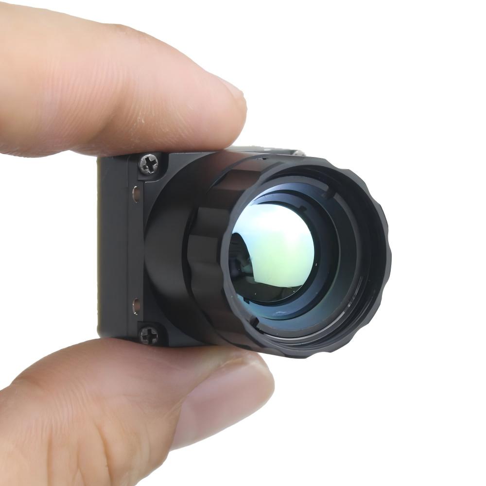
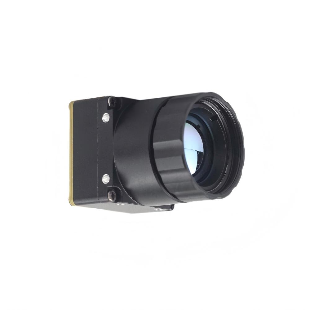
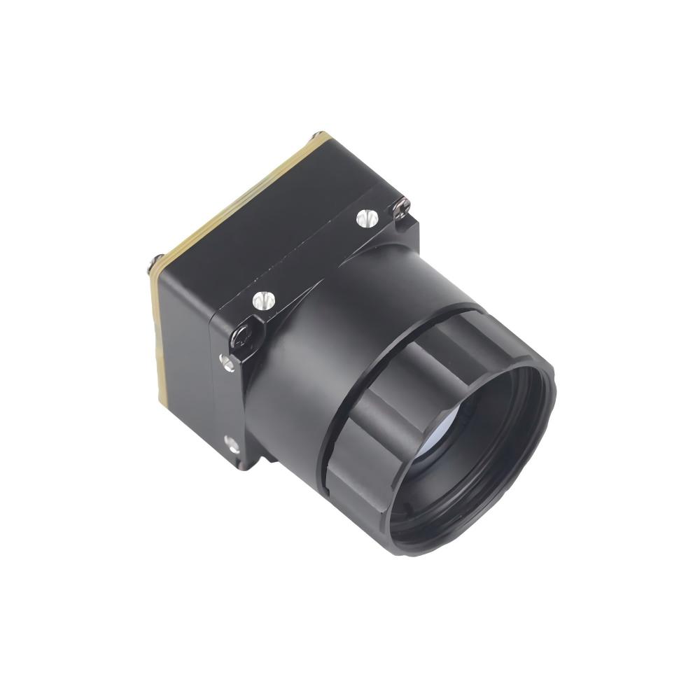
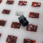
Option A: Uncooled Infrared Mipi 640 384 256 9mm Thermal Imaging Camera Module For Drones
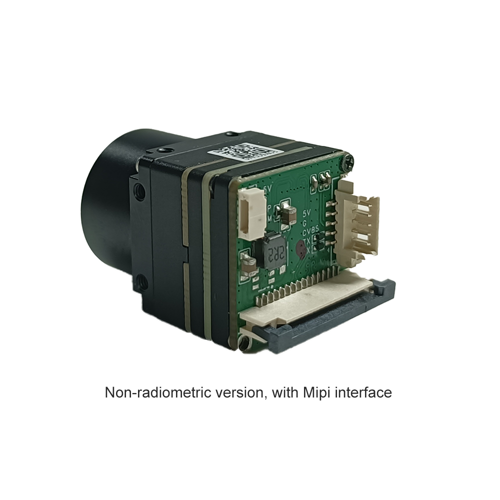
Uncooled Infrared Mipi 640 384 256 9mm Thermal Imaging Camera Module For Drones
The Mini2 is a lightweight MIPI core engineered for advanced system integrators who need a direct high-speed ribbon connection to their host processor. It drops a 640x512 microbolometer array into a ultra-low-profile chassis, solving the mechanical limits of compact search, rescue, and inspection platforms.
- ✅ 9mm Prime Lens: Optimized wide-angle design built to survey large fields quickly.
- ✅ Raw MIPI CSI-2 Connectivity: Eliminates video encoders and controllers, cutting down latency and saving weight.
- ✅ Highly Sensitive Core: Capable of extracting clean radiometric data through heavy smoke or fog.
- ✅ Dynamic Silicon Scaling: Available in 640, 384, or 256 array designs to match your specific performance budget.
This core is perfect for clean, high-performance integration builds where you compile dedicated C++ pipelines on localized hardware (like Jetson platforms), avoiding the extra electronics of standard USB-to-serial conversion blocks.
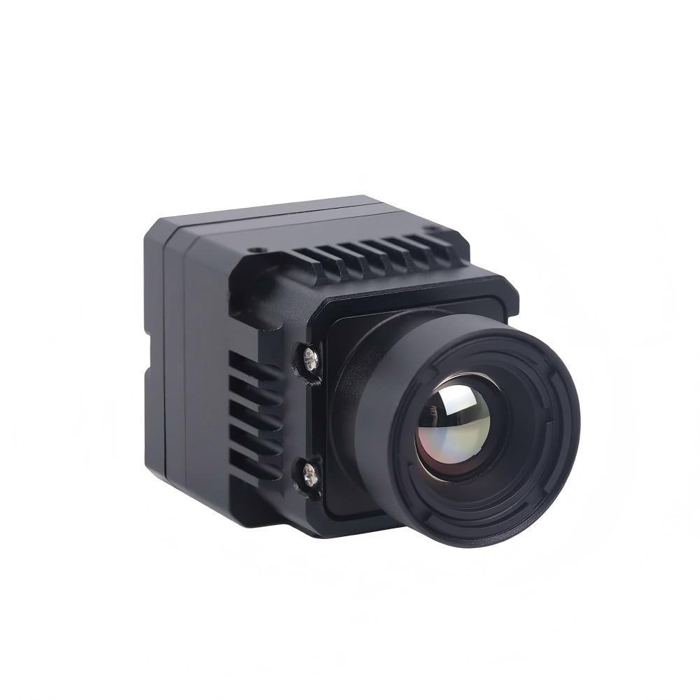
Option B: Uncooled LWIR USB Mini 640*512 Thermal Imaging Camera Core Module For Drones Similar To DJI
Uncooled LWIR USB Mini 640*512 Thermal Imaging Camera Core Module For Drones Similar To DJI
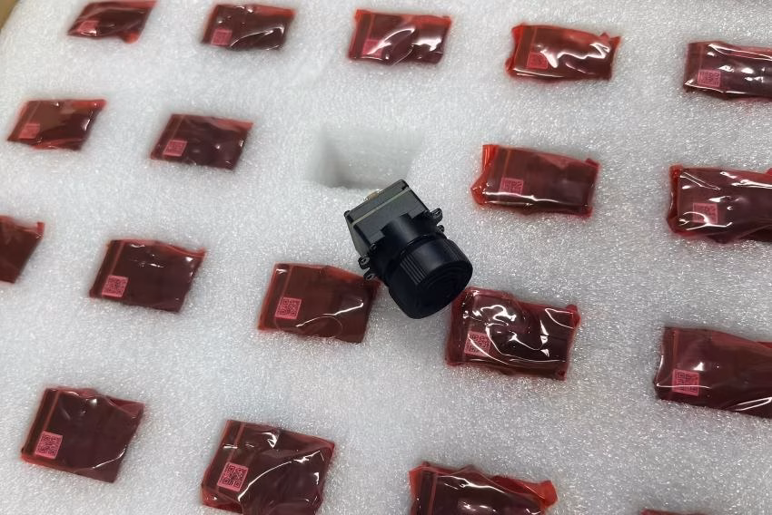
This module features a highly compact physical footprint measured at just 21mm x 21mm. It addresses the needs of integrators looking for quick connectivity, a wide selection of focal lengths, and simple, driver-free software compatibility on standardized operating system layers.
- ✅ Tiny Physical Envelope: At just 21mm x 21mm, this CNC-milled chassis slides into custom payloads or DJI mounts with ease.
- ✅ Wide Optical Range: Supports lenses from wide 5mm up to long-range 150mm options for specialized industrial tasks.
- ✅ Standard UVC USB Connection: Avoids kernel driver headaches; works instantly on Linux, Windows, or Android builds.
- ✅ Robust Hardware: Designed with clean mechanical damping to withstand the shocks of field landings.
This module is highly popular for research teams and builders doing rapid prototyping. If your primary goal is to drop a high-res thermal sensor onto an existing platform without spending weeks writing custom drivers, this USB core is your best bet.
7. Step-by-Step OEM Integration: Hardening, Power, & Thermal Radiometry
Getting a raw thermal camera working on a drone is a multi-step engineering process. Connecting the wires is only half the battle; you also have to filter electrical feedback, design mechanical isolators, and calibrate the data stream.
Section 7.1: Power Isolation and EMC Hardening
Modern brushless drone motors draw high amounts of current dynamically, releasing intense electromagnetic feedback and noise back across your power distribution board (PDB). This high-frequency feedback can ruin your thermal imaging feed, causing vertical stripes and horizontal banding across your display. Here is how we prevent this on the bench:
- ⚙️ Implement Independent Power Isolation: Always run your camera core off its own Low-Dropout (LDO) regulator. Do not tie the camera directly to your primary flight battery or a general-use BEC that powers heavy digital servos or gimbals.
- ⚙️ Install Low-ESR Decoupling Capacitors: Place high-quality, low-ESR bypass capacitors (usually a 10µF tantalum capacitor in parallel with a 0.1µF ceramic option) right next to the module's power input pin to absorb high-frequency spikes.
- ⚙️ Isolate Cabling Paths: Keep your high-frequency lines (especially MIPI and USB) well away from ESC output cables and motor phases. Wrap your signal lines in copper shielding foil connected directly to system ground.
Section 7.2: Stabilization and Vibration Dampening
The high-frequency vibration from your brushless motors can create serious "jello" effects and motion blur. This ruins image clarity and confuses edge AI and object-tracking models.
- ⚙️ Mount on an Active 3-Axis Gimbal: Use a high-quality brushless gimbal running high loop speeds (at least 1000Hz). When balancing, make sure the camera and lens assembly sits exactly at the pivot point of the pitch axis to avoid overheating the motors.
- ⚙️ Calibrate Elastomeric Isolators: Use high-damping silicone or rubber balls on your isolation plate (Shore 40A is usually a good target). To select the right dampeners, calculate your exact payload mass; if the dampeners are too hard, they will pass vibration right to your lens, and if they're too soft, they'll sag.
Section 7.3: Thermal Calibration and Radiometric Integration
If you need your sensor to output highly accurate temperature readings, you have to manage its internal temperature. As the core works, heat builds up on the silicon substrate, which changes your baseline radiometric offsets.
- ⚙️ Manage Calibration Shutter Cycles (NUC): The uncooled core periodically drops its internal mechanical shutter to reset pixel offsets. This pauses the video for a brief moment. To prevent this shutter click during critical maneuvers, use your companion computer to send calibration trigger commands via Mavlink during stable phases of flight.
- ⚙️ Correct for Environmental Shifts: Humidity, wind speed, and the dynamic emissivity of different target materials can alter the thermal readings on your sensor. Use your SDK (Software Development Kit) to feed real-time flight altitude, atmospheric humidity, and surface emissivity settings directly to the core during flight.

8. Industrial Integration FAQ: Custom FPV, Edge Inference, & Flight Dynamics
Can I integrate a third-party thermal module into consumer drones like DJI or FPV setups?
Why choose an Edge AI thermal imaging module over standard thermal cameras?
How do SWaP-C thermal modules improve drone flight times?
📚 References & Further Reading
- 👉 Industry Standard: Amphenol Aerospace High-Reliability Connections
- 👉 Optical Engineering: LightPath Technologies Chalcogenide Optical Assemblies
- 👉 Related Guide: Mini 640 Uncooled LWIR Thermal Camera Integration Guide