









High-Res USB Thermal Imaging Camera Module for Raspberry Pi: 640x512 Integration Guide
2026年7月1日
Thermal True IR Night Vision Camera Module: B2B Integration Guide
2026年7月1日
Ultimate Guide to Thermal Module Camera Integration: 384x288 Solutions for Drones, Raspberry Pi & B2B OEM Projects
In the rapidly evolving landscape of industrial automation, unmanned aerial vehicles (UAVs), and edge-deployed computer vision, the requirement for high-resolution thermal imaging has shifted from a specialized luxury to a fundamental architectural necessity. Integrating a thermal module camera into modern embedded systems demands more than standard off-the-shelf hobbyist hardware. System engineers, R&D directors, and OEM product managers face complex hurdles, including strict weight budgets (SWaP), high-frequency signal integrity, and the engineering overhead of raw radiometric data extraction. Let's be real: historically, project pipelines stalled because of rigid, closed-source consumer camera cores or poor SDK support that failed to bridge the gap between custom hardware interfaces and standard embedded operating systems like Linux or ROS.
To overcome these barriers, industrial-grade uncooled LWIR (Long-Wave Infrared) cores featuring a 384x288 pixel resolution have emerged as the industry's sweet spot. Balancing thermal sensitivity, weight, and optical range, these 12μm microbolometer cores provide over double the active sensor area of entry-level 256x192 sensors without the exponential cost and footprint of VGA-class cores. This comprehensive guide details the technical, electrical, and optical considerations for integrating high-performance 384x288 thermal camera modules into drones, custom Raspberry Pi systems, and proprietary IoT hardware, backed by state-of-the-art engineering practices from market leaders.
Table of Contents
- 👉 1. Architectural Overview of LWIR Sensor Engineering
- 👉 2. Demystifying the Resolution Hierarchy: 384x288 vs. 256x192 Cores
- 👉 3. Electrical Interface Architectures: MIPI, USB, and CVBS
- 👉 4. Raspberry Pi and Linux System Integration Blueprint
- 👉 5. Drone Gimbal Payload Engineering and SWaP-C Optimization
- 👉 6. Purpleriver 384x288 Thermal Module Product Showcase
- 👉 7. Industrial OEM/ODM Customization Pipelines
- 👉 8. Hardware Integration & Implementation FAQ
1. Architectural Overview of LWIR Sensor Engineering
Here’s the deal: under the hood of any real-world thermal camera module lies an uncooled microbolometer sensor array engineered to detect radiation in the Long-Wave Infrared (LWIR) spectrum, typically ranging from 8μm to 14μm. Unlike visible-light silicon CMOS sensors that rely on photon-induced charge generation, uncooled thermopiles or microbolometers use materials whose electrical resistance changes dynamically as they absorb incident infrared radiation. In the shop, we swear by Vanadium Oxide (VOx) thin films as the active sensing material. Why? Because they offer exceptional Temperature Coefficient of Resistance (TCR) and keep 1/f noise to an absolute minimum compared to cheaper amorphous silicon (a-Si) alternatives.
The processing chain within a modern uncooled thermal core begins when incoming LWIR radiation passes through a high-purity Germanium lens assembly. These lenses aren't standard glass—they're coated with specialized Anti-Reflective (AR) layers to maximize transmission efficiency in the infrared bands. Once the targeted infrared energy hits the Focal Plane Array (FPA) consisting of a VOx microbolometer matrix, the individual pixel components experience a slight temperature change. This thermal displacement causes a shift in electrical resistance across each individual micro-bridge structure. The embedded Readout Integrated Circuit (ROIC) subsequently converts these minute resistance fluctuations into 14-bit or 16-bit raw digital signals via a high-speed internal Analog-to-Digital Converter (ADC). Finally, an on-board Digital Signal Processor (DSP) or dedicated FPGA executes complex calibration routines, such as Non-Uniformity Correction (NUC), Bad Pixel Replacement (BPR), and radiometric mapping, outputting a highly stable, low-noise thermal stream.
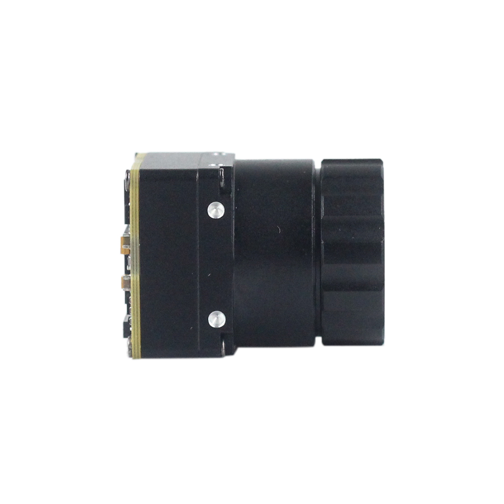
The Role of Pixel Pitch (12μm vs. 17μm)
The thermodynamic performance of a thermal sensor is governed in part by its pixel pitch—the physical distance from the center of one pixel element to the center of the next. Switching from old-school 17μm arrays to modern 12μm pixel pitch designs isn't just a minor tweak; it’s a total game-changer for industrial electro-optics:
- ✅ Optical Efficiency: A smaller pixel pitch allows a 384x288 array to be packaged on a significantly smaller physical sensor die. This reduces the overall sensor footprint and allows system architects to utilize smaller, lighter, and more cost-effective Germanium optical elements to achieve the identical Field of View (FOV). It means you save weight without sacrificing your view.
- ✅ Thermal Time Constant: With smaller individual pixel volumes, the thermal mass of each VOx bridge is radically reduced. This allows the pixel to respond faster to transient temperature changes, resulting in decreased thermal lag and motion blur during high-speed scanning or drone flight.
Thermal Sensitivity (NETD)
Noise Equivalent Temperature Difference (NETD) is the primary metric evaluating the sensitivity of a thermal module camera. Expressed in millikelvins (mK), NETD defines the minimum temperature difference that the sensor can resolve from its background noise floor. Industrial-grade modules exhibit an NETD ≤ 40mK or ≤ 50mK at $f/1.0$. This signifies that the sensor can easily detect temperature differences as small as 0.04°C. Achieving such low NETD values requires high-precision calibration parameters executed via on-board hardware, including Real-time Non-Uniformity Correction (NUC) algorithms and bad pixel replacement.
2. Demystifying the Resolution Hierarchy: 384x288 vs. 256x192 Cores
When you're out in the field designing an embedded thermal system, engineers must choose between different sensor resolutions. While entry-level 256x192 cores—like those cheap hobbyist-grade USB dongles or compact consumer thermal sensors—are highly cost-efficient on paper, they fall flat in critical industrial, commercial, and defense applications. Selecting a 384x288 uncooled thermal camera module provides massive operational advantages:
The Information Density Advantage
Let's look at the math. A 384x288 sensor yields exactly 110,592 discrete pixels of thermal data. In contrast, a 256x192 sensor yields only 49,152 pixels. Moving to a 384x288 configuration delivers a 125% increase in total active data resolution. This massive expansion of spatial data prevents sub-pixel averaging errors, enabling edge artificial intelligence (Edge AI) models to isolate target contours much earlier and with greater accuracy. The higher pixel density also allows for more precise temperature measurements, as the camera is less likely to aggregate the temperature of a small target with the colder background environment.
Spatial Resolution and Instantaneous Field of View (iFOV)
The iFOV measures the spatial resolution of an individual pixel, defining the smallest target area that can be resolved at a specific distance. Mathematically, iFOV is expressed as:
If we examine a fixed 19mm focal length Germanium lens paired with a 12μm microbolometer:
At a distance of 100 meters, each pixel resolves a physical spot size of approximately 6.3 cm. In critical security applications, machine vision setups, or aerial surveys, this increased spatial resolution ensures accurate target identification, preventing dangerous false positives. For a deeper analysis of choosing target LWIR optical assemblies, refer to this comprehensive industry LWIR core selection guide.
3. Electrical Interface Architectures: MIPI, USB, and CVBS
To successfully integrate a thermal module camera into custom hardware, you must select the appropriate hardware communication layer. Industrial 384x288 thermal camera modules provide three primary electrical interfaces, each suited to distinct engineering requirements:
| Interface Type | Data Depth & Signal Type | Best Suited For | Hardware Overhead |
|---|---|---|---|
| MIPI CSI-2 | 14-bit RAW Digital data, high-bandwidth path | Embedded SOCs (NVIDIA Jetson, Rockchip) | High (Requires custom kernel drivers/BSPs) |
| USB (UVC + Bulk) | Dynamic Color Video & Radiometric raw matrices | Raspberry Pi, industrial PCs, rapid prototyping | Low (Standard plug-and-play driver stacks) |
| CVBS | Standard analog composite video (PAL/NTSC) | Analog FPV systems, legacy analog monitors | Minimal (Direct wiring to transmitter/monitor) |
1. MIPI CSI-2 (Mobile Industry Processor Interface)
MIPI CSI-2 has emerged as the gold standard for high-bandwidth, direct-to-processor camera connections. It transmits uncompressed, high-bit-depth raw digital thermal data (typically 14-bit or 16-bit) directly to the video capture pipeline of the host system-on-chip (SoC). This allows the host processor to access the raw sensor values without any decompression latency or protocol translation overhead, opening up opportunities for hardware-accelerated image signal processing (ISP) using specialized GPU or NPU modules.
While MIPI CSI-2 offers the lowest possible frame latency and maximum system performance, it demands complex, custom board support package (BSP) driver configurations. Let me tell you from experience: routing differential high-frequency lanes on custom PCBs requires careful length-matching to prevent phase distortion and EMI. Keep those cable runs under 10 cm unless you enjoy debugging signal integrity headaches with active, dedicated signal extenders.
2. USB Interface (UVC & Bulk Endpoints)
The Universal Serial Bus (USB) interface is preferred for rapid development on single-board computers (SBCs) and general development workstations. This interface utilizes a bifurcated approach: it streams pre-processed, colorized thermal video feeds using the standard USB Video Class (UVC) protocol, while concurrently exposing raw 14-bit radiometric temperature matrices over custom USB bulk transfer endpoints.
The primary advantage of the USB approach is physical plug-and-play simplicity. Most modern operating systems (Linux, Windows, macOS) ship with native UVC drivers, eliminating the need to compile custom kernel modules. However, keep in mind that these systems exhibit higher latencies compared to direct MIPI pipelines, and managing high-bandwidth bulk data transfers can introduce significant CPU overhead on low-power host microcontrollers.
3. CVBS (Composite Video Baseband Signal)
CVBS is an analog, standard-definition television transmission format (NTSC or PAL) widely used in legacy systems. The on-board image processor of the thermal module reconstructs the digitized thermal readings, maps them to a user-selectable color palette, and translates the resulting visual stream into an analog waveform. This output can be transmitted directly over co-axial lines or high-power analog RF video links.
CVBS features exceptionally low delay, high resistance to physical electromagnetic interference, and the ability to operate across long cable runs (up to 100 meters) without signal dropouts. The primary limitation is data content: because the signal is strictly analog video, all raw thermodynamic pixel metadata is lost, making it impossible to perform post-processing temperature calculations on the receiving hardware.
4. Raspberry Pi and Linux System Integration Blueprint
Integrating a high-performance thermal camera core with a single-board computer like the Raspberry Pi (4/5) or an NVIDIA Jetson module allows for rapid prototyping of smart IoT cameras, edge AI thermal classifiers, and portable test instrumentation. Real-world implementation relies heavily on robust data ingest patterns that bridge kernel-space acquisition with user-space processing applications.
The system architecture begins at the Linux kernel level, where the physical core is recognized via the standard USB UVC or serial drivers. The driver maps the incoming frames into the Virtual Video for Linux (V4L2) core, making them accessible to user-space applications through the /dev/videoX device nodal interface. Control paths, configuration updates, and micro-command payloads are routed concurrently through a virtual serial interface (such as /dev/ttyUSBX) governed by the host application's operational state.
Navigating the Software Pipeline
To capture and process the thermal stream without dropping frames or stalling the system queue, developer applications can leverage highly efficient software pipelines. Using a system utility framework like GStreamer, developers can structure low-overhead capture networks that route raw YUYV or raw 16-bit greyscale (Y16) frame buffers into OpenCV processing threads with minimum latency:
gst-launch-1.0 -v v4l2src device=/dev/video0 ! video/x-raw,format=Y16,width=384,height=288 ! videoconvert ! appsink
This command captures the raw 16-bit thermal stream, bypasses complex color conversion processes at the driver level, and forwards the raw pixel units. The application can then analyze, manipulate, and colorize the frames programmatically.
Radiometric Data Extraction and SDK Communication
For accurate thermographic diagnostics, applications must be able to convert raw pixel data into absolute temperature values. The following Python integration pipeline demonstrates how to capture raw frames via OpenCV, extract the 14-bit digital numbers, apply factory calibration parameters, and visualize the processed output in real-time:
import cv2
import numpy as np

# Configure V4L2 video capture stream from the thermal module (raw format)
try:
    cap = cv2.VideoCapture(0, cv2.CAP_V4L2)
    cap.set(cv2.CAP_PROP_FOURCC, cv2.VideoWriter_fourcc('Y', '1', '6', ' '))
    cap.set(cv2.CAP_PROP_CONVERT_RGB, False)
except Exception as e:
    print(f"Error accessing thermal module camera: {e}")
    exit(1)

while True:
    ret, frame = cap.read()
    if not ret:
        break

    # Raw 14-bit radiometric data is packaged in 16-bit uint representation
    raw_14bit = frame.astype(np.uint16)

    # Apply calibration formula: Temperature (Celsius) = (Raw_Value * 0.1) - 273.15
    # This example maps raw digital numbers directly to Celsius
    temperature_celsius = (raw_14bit * 0.1) - 273.15

    # Isolate maximum temperature target point in the FOV frame
    min_val, max_val, min_loc, max_loc = cv2.minMaxLoc(temperature_celsius)

    # Normalize 14-bit raw values to standard 8-bit for visualization
    norm_frame = cv2.normalize(raw_14bit, None, 0, 255, cv2.NORM_MINMAX, dtype=cv2.CV_8U)
    colorized_thermal_feed = cv2.applyColorMap(norm_frame, cv2.COLORMAP_JET)

    # Overlay temperature coordinates on top of user visualization frame
    cv2.putText(colorized_thermal_feed, f"Max Temp: {max_val:.2f} C", (15, 30),
                cv2.FONT_HERSHEY_SIMPLEX, 0.7, (255, 255, 255), 2)

    cv2.imshow("Real-Time Thermal Analysis Map", colorized_thermal_feed)
    if cv2.waitKey(1) & 0xFF == ord('q'):
        break

cap.release()
cv2.destroyAllWindows()
5. Drone Gimbal Payload Engineering and SWaP-C Optimization
Deploying thermal cameras on small unmanned aircraft systems (sUAS) requires strict adherence to Size, Weight, Power, and Cost (SWaP-C) constraints. Adding weight directly impacts battery runtimes, while electromagnetic interference can jeopardize flight stability.
The electrical design begins with clean power distribution. Unregulated aircraft bus power (typically 12V to 24V from multi-cell LiPo batteries) is highly susceptible to high-frequency voltage ripples generated by Electronic Speed Controllers (ESCs) and high-RPM brushless DC (BLDC) motors. Without adequate filtration, this electrical noise can degrade the performance of highly sensitive thermography arrays, showing up as visual banding or noise in the thermal output.
To prevent this, we always route incoming DC lines through a specialized high-rejection, low-pass power filter (such as an LC filter network) before passing the voltage to a dedicated low-dropout (LDO) linear regulator. This regulator steps the voltage down to a clean 3.3V or 5V DC supply, maintaining a high Power Supply Rejection Ratio (PSRR) to shield the delicate sensor arrays or on-board processing units from power-line noise.
Drone Mechanical & Environmental Isolation Guide
- ⚙️ Vibration Dampening & Microphonics: High-frequency kinetic impulses from fast-spinning props can cause mechanical vibrations that distort the microbolometer readings. To mitigate this microphonic noise, mount the camera core to the gimbal frame using low-durometer silicone gel vibration dampers, protecting the uncooled sensor from micro-vibration noise.
- ⚙️ Electromagnetic Shielding (EMI): High-power RF telemetry modules and video transmitters mounted close to thermal cameras can induce pattern noise across the uncooled sensor array. Fully housing the thermal camera module inside an industrial CNC aluminum enclosure provides mechanical protection and functions as a Faraday shield against EMI.
- ⚙️ Environmental Protection & Calibration: Airborne payloads face rapid temperature and humidity swings during high-speed ascents and descents. Ensure the system can handle hot and cold conditions without losing optical focus, and implement automated shutter-based or software-driven NUC algorithms to maintain accuracy across changing ambient temperatures. For more on this, check out this diagnostic look at thermal camera environmental testing.
6. Purpleriver 384x288 Thermal Module Product Showcase
Purpleriver designs and manufactures high-performance uncooled long-wave infrared thermal camera cores. Their systems combine uncooled microbolometer sensor elements with robust ... image signal processing pipelines. This makes them ideal for commercial application fields like safety inspection, research laboratories, and embedded drone payloads.
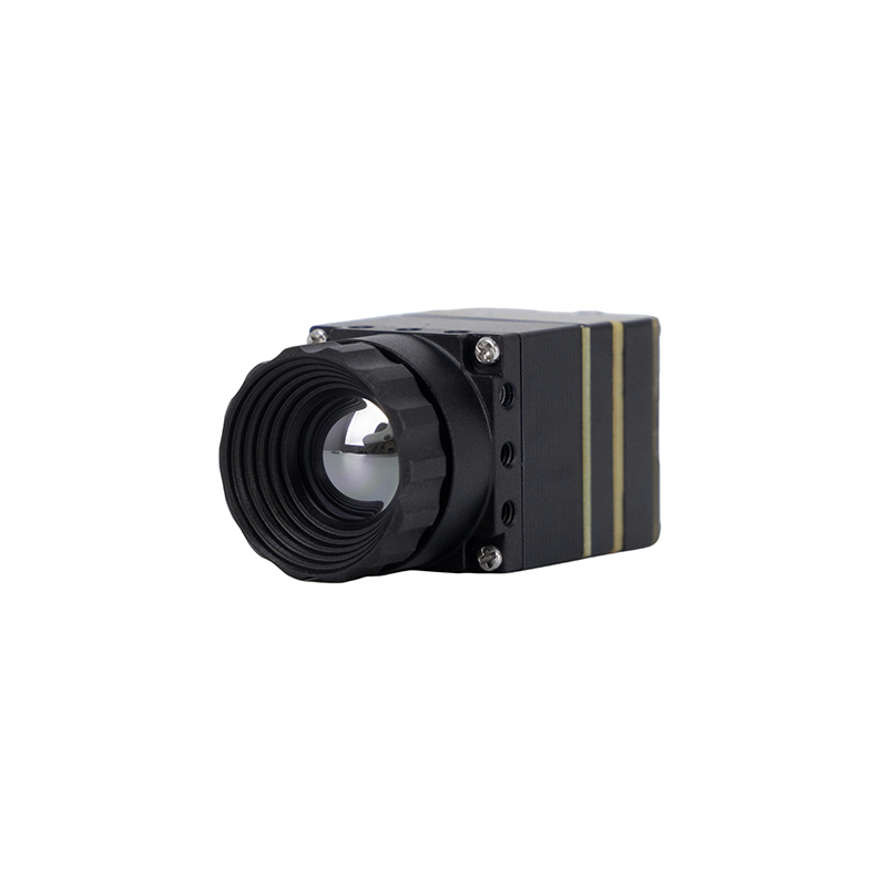
MD Series 384x288 Uncooled Infrared Thermal Camera Module
The Purpleriver thermal camera module is designed for industrial-grade precision in applications such as security, temperature monitoring, and drone integration. Featuring an uncooled infrared detector with a 12μm pixel pitch, it delivers high sensitivity and sharp thermal imaging. Its compact size, plug-and-play functionality, and multiple interfaces (MIPI/USB/CVBS) ensure versatile and rapid integration into various systems. Backed by a team with a Hong Kong University of Science and Technology background and former Huawei Hisilicon expertise, this module offers OEM/ODM customization to meet specific project requirements, ensuring unparalleled performance and adaptability.
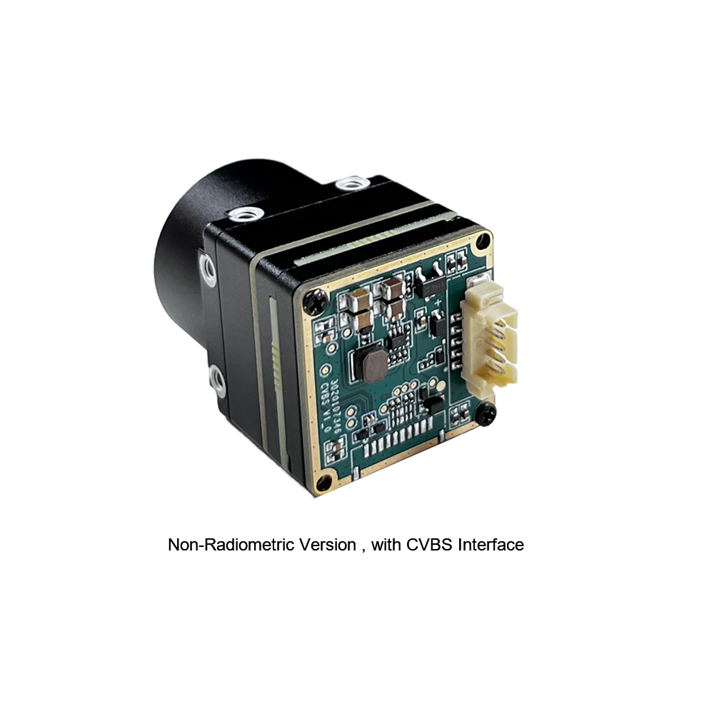
Uncooled Mini 384*288 Thermal Camera Module For Drones
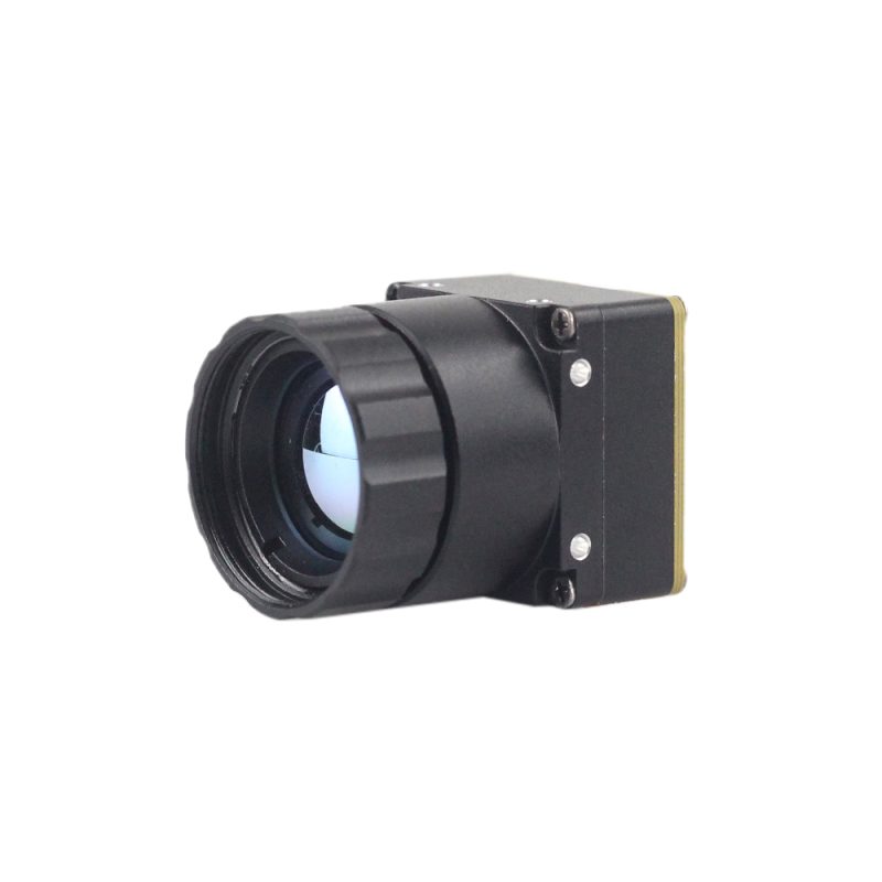
The MINI series infrared thermal imaging temperature measurement module is a high-precision, small-sized, and universal online temperature measurement infrared thermal imager. It uses high-quality detectors, high resolution, stable performance, and powerful functions. It is equipped with multiple interfaces, making it a preferred product in application fields such as machine vision, safety inspection, intelligent manufacturing, equipment maintenance, robot drone airborne, and so on.
Comparative Specifications Matrix
To help system designers select the appropriate hardware core for their projects, the physical, electrical, and optical operational characteristics of the MD Series and MINI Series are compared below:
| Technical Parameters | MD Series 384x288 Module | Uncooled MINI 384x288 Drone Core |
|---|---|---|
| Resolution (FPA Layout) | 384 x 288 Pixels | 384 x 288 Pixels |
| Pixel Pitch Size | 12μm microbolometer structure | 12μm microbolometer structure |
| Spectral Range | 8μm to 14μm (LWIR) | 8μm to 14μm (LWIR) |
| Sensitivity (NETD) | ≤ 40mK (@25°C, f/1.0) | ≤ 50mK (@25°C, f/1.0) |
| Available Interfaces | MIPI CSI-2, USB 2.0 (UVC), CVBS Analog | USB 2.0 (UVC), CVBS Analog Video |
| Thermographic Functionality | Advanced regional radiometric analysis | Real-time temperature measurement |
| Typical Power draw | Extremely low (< 1.1 W) | Optimized low power (< 0.9 W) |
| Target Customizations | Excellent (Deep B2B OEM custom designs) | Payload adaptation & Gimbal integrations |
7. Industrial OEM/ODM Customization Pipelines
Off-the-shelf consumer thermal imagers are rarely suitable for complex industrial applications. Specialized designs require tailored physical configurations, custom lens arrangements, and unique communication protocols.
The customization pipeline begins during the initial requirements definitions, where product managers establish electrical, physical, and atmospheric operational boundaries. Once these parameters are set, engineers translate standard module command sets into industrial system protocols (such as SPI, Modbus, or CAN Bus formats). This protocol layer allows the camera's configuration registers to communicate seamlessly with PLCs, smart automotive nodes, or edge flight controllers. Concurrently, engineers work to optimize optical components and protective factors to ensure stable thermal performance in challenging deployable environments.
Protocol Customization (SPI, Modbus, CAN Bus)
Modern industrial and military architectures rely on highly robust communication protocols. While USB is suitable for basic workbench tests, field integrations demand cleaner bus architectures:
- ⚙️ CAN Bus (Controller Area Network): Essential for automotive, aerospace, and robotic system controls. It enables long-distance, error-resistant communications between various nodes without requiring a centralized host-PC architecture.
- ⚙️ Modbus Protocol: The standard for programmable logic controllers (PLCs) in manufacturing plants. This interface allows the camera to trigger alarms or control shutoffs when a component exceeds a predefined temperature threshold.
- ⚙️ Low-Power SPI (Serial Peripheral Interface): Ideal for microcontrollers and edge processors. SPI allows for rapid data transfers across custom carrier boards while minimizing complexity and power consumption.
Environmental Optimization & Tough Protective Coatings
Deploying sensors in extreme industrial thermal chambers or marine operations requires ruggedized system protection:
- ⚙️ DLC (Diamond-Like Carbon) Optical Coatings: Protects external-facing Germanium lenses from abrasive sand, dirt, and chemical exposure, ensuring long-term field survivability.
- ⚙️ Conformal PCB Isolation Coatings: Shields sensitive board components from moisture, condensation, salt spray, and corrosive atmospheres.
- ⚙️ Automated Shutter Calibration: Integrates robust calibration targets that allow the camera core to maintain measurement accuracy across wide operating temperature changes (-40°C to +80°C).
To optimize performance across these harsh conditions, B2B manufacturers regularly source advanced optical assemblies through specialized precision partners, such as Rising Optics, to deliver accurate dual-spectrum focusing capabilities. To learn more about general industrial and outdoor portable thermal designs, check out this guide on thermal imaging tools.
8. Hardware Integration & Implementation FAQ
How do I stream real-time, high-resolution thermal video to a Raspberry Pi or Linux system?
Real-time stream integration into Raspberry Pi or general x86/ARM Linux architectures can be achieved by utilizing Purpleriver's comprehensive Software Development Kits (SDK) alongside standard operating system frameworks. Unlike standard consumer sensor platforms, which lack open-source code and are locked down to proprietary app frameworks, Purpleriver modules provide a highly versatile, open-system architecture.
For the most reliable integration, we recommend utilizing the USB-UVC digital output pipeline. In this configuration, the Linux operating system recognizes the camera dual-port structure. This structures the video feed as a standard raw YUV output on the primary /dev/videoX channel, while simultaneously maintaining a raw command/radiometric link via /dev/ttyUSBX or virtual COM interfaces. Through this configuration route, developers can run our optimized GStreamer capture commands directly from memory space pipelines, or read raw matrices using Python and OpenCV integration codes without suffering from dropped frame packets. If your project has strict space or layout limitations, please consult with our team regarding custom MIPI CSI device-tree bindings for custom carrier designs.
For DIY and commercial integration, why should I upgrade from a 256x192 sensor to a 384x288 uncooled thermal camera module?
Moving from an entry-level 256x192 sensor (such as the hobbyist-grade Tiny1 series) to an industrial-grade 384x288 uncooled thermal camera module with a 12μm pixel pitch provides a massive leap in spatial processing performance. While a 256x192 sensor may be sufficient for basic thermal checks, its low pixel density limits its effectiveness at longer distances.
The 384x288 resolution upgrade delivers more than double the spatial data points (110,592 vs. 49,152 pixels). This has several major practical benefits: First, the increased sensor density provides the sharpness and range needed for critical operations like drone mapping, security monitoring, and automated manufacturing. Second, the improved spatial resolution (iFOV) allows you to resolve small targets at much greater distances, preventing accuracy loss from sub-pixel temperature blending. Third, edge AI models can detect and classify objects faster and with fewer false positives, ensuring reliable performance in demanding environments. Additionally, our advanced 12μm VOx sensor microbolometers optimize spatial performance without increasing the lens's physical size. This ensures your systems remain light, compact, and highly efficient.
Are these thermal module cameras suitable for custom weight-sensitive payloads like drone gimbals and thermal scopes?
Yes, Purpleriver's MINI Series thermal cores are designed specifically for weight-sensitive applications. Our hardware and firmware are optimized to deliver maximum performance within strict weight budgets, making them ideal for multi-spectral drone gimbals, compact hand-held thermal scopes, and miniature military/industrial optics.
Our core design team leverages their extensive R&D backgrounds from the Hong Kong University of Science and Technology and former Huawei Hisilicon silicon platform engineering to optimize every design. These optimizations are built into every core, including micro-sized form factor, low power consumption (less than 0.9W on mini layouts), and complete OEM/ODM customization options. To integrate the best microchip solutions with our camera modules, system architects often coordinate with major semiconductor companies like JM Chip to design custom, low-power edge processing hubs and smart companion boards.
📚 References & Further Reading
- Industry Standard: JM Chip Semiconductor Technologies
- Industry Standard: Rising Optics Precision Lens Engineering
- Related Guide: Thermal Imaging Camera Module Guide: Choosing the Right LWIR Core
- Related Guide: High and Low Temperature Humidity Environmental Test Operations
- Related Guide: Heat Vision Revolution: Essential Optical Thermal Tools





