







High-Resolution Thermal Imaging Camera Module for Raspberry Pi: The Ultimate Edge AI Integration Guide
2026年6月24日
Ultimate Guide to Thermal Module Camera Integration: 384x288 Solutions for Drones, Raspberry Pi & B2B OEM Projects
2026年7月1日
High-Res USB Thermal Imaging Camera Module for Raspberry Pi: 640x512 Integration Guide
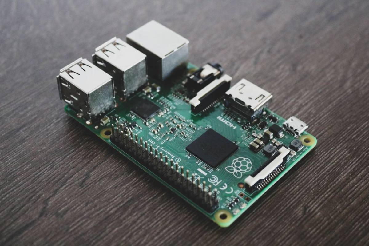
Here's the deal: if you are trying to deploy high-resolution thermal imaging on single-board computers (SBCs) like the Raspberry Pi, you've probably run into some wall. Early experiments with low-res I2C thermopile arrays were fine for hobby projects, but modern industrial applications demand serious hardware. We are talking high thermal sensitivity (NETD ≤ 50 mK), rapid frame rates, and dense spatial resolution. This guide is a complete, hands-on system integration manual for hardware engineers, R&D specialists, and software architects putting together a usb thermal imaging camera module for raspberry pi. In the shop, we know that success comes down to understanding the physics, choosing the right interface, matching the optics, and writing efficient software pipelines. We will break down the physics of Uncooled Long-Wave Infrared (LWIR) sensors, compare the dirty details of USB/UVC vs. MIPI CSI-2 interfaces, analyze lens choices, and step through a production-ready Python pipeline using Linux V4L2 drivers and OpenCV.
Table of Contents
- 👉 1. The Physics of LWIR Microbolometer Sensors
- 👉 2. USB vs. MIPI Integration for Raspberry Pi
- 👉 3. Optics and Lens Selection Criteria
- 👉 4. Technical Specifications & Product Selection
- 👉 5. Software Integration: V4L2, OpenCV, and Python SDK
- 👉 6. Advanced Image Processing: Radiometric Mapping & NUC
- 👉 7. Industrial Field Deployments
- 👉 8. Technical Deep-Dive FAQ
1. The Physics of LWIR Microbolometer Sensors
To build a thermal system that actually works in the field, you have to look closely at the underlying physics. Standard CMOS and CCD sensors capture reflected visible light in the 400nm to 700nm range. Thermal imaging is different. We are looking at the Long-Wave Infrared (LWIR) band, which stretches from 8 µm to 14 µm.
Everything around us—motors, machinery, circuit boards, human bodies—emits thermal energy as blackbody radiation. Planck's Law and Wien's Displacement Law describe this behavior. When we calculate peak emission wave length, Wien's law makes it simple:
λmax = 2897.8 µm·K / T
If your target is sitting at a normal room temperature of 300 K (about 27°C or 80°F), its peak emission hits right at 9.66 µm. This sits perfectly in the center of the LWIR atmospheric transmission window. This band is critical because atmospheric gases like carbon dioxide and water vapor don't absorb much energy here, allowing your signal to travel to the sensor with minimal attenuation.
Theoretical Performance Indicators:
Vanadium Oxide (VOx) vs. Amorphous Silicon (a-Si): In the field, VOx core matrices are preferred for high-end applications. VOx material exhibits a superior Temperature Coefficient of Resistance (TCR) compared to silicon. This minimizes thermal noise and yields a cleaner raw image. Selecting a high-resolution thermal camera module 640x512 uncooled LWIR cores utilizing VOx substrates ensures raw target detail holds crisp over broad operating conditions.
Most rugged commercial camera modules use uncooled microbolometers. Picture an array of tiny, suspended silicon bridges, each coated with a temperature-sensitive material like Vanadium Oxide. When LWIR photons hit a pixel, the bridge heats up, changing its electrical resistance.
The Read-Out Integrated Circuit (ROIC) sweeps a biased current through the array, measures those resistance changes, and constructs the digital thermal picture. Two key variables dictate how well the sensor performs:
- ⚙️ Pixel Pitch: The center-to-center distance between adjacent pixels. Shrinking this down from 17 µm to 12 µm lets us package a 640x512 array into a compact, lightweight core that fits on small drones or tight enclosures.
- ⚙️ NETD (Noise Equivalent Temperature Difference): This is your signal-to-noise benchmark. It defines the smallest temperature difference the camera can resolve. If you are doing detail-sensitive diagnostics, you want an NETD of ≤40 mK or ≤50 mK. Higher values make the image look like old television static.
2. USB vs. MIPI Integration for Raspberry Pi
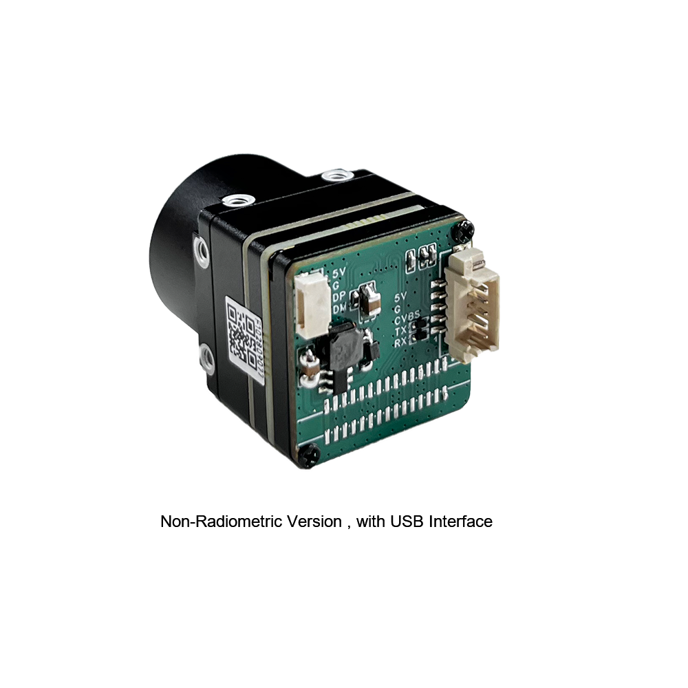
When integrating a high-end thermal core with a Raspberry Pi, you face a critical fork in the road: do you go with USB (UVC protocol) or native MIPI CSI-2?
USB Interface (UVC Protocol)
USB modules rely on standard USB Video Class (UVC) microcode running on an onboard microcontroller or FPGA. The chip packages the raw ROIC frame into a digital format (YUYV or raw 16-bit greyscale) and ships it over the USB bus.
The big benefit here is ease of use. Linux has had native uvcvideo drivers baked into the kernel for years. Plug the module in, and it instantly shows up as /dev/video0. No custom device-tree overlays, no compile errors, and no kernel matching headaches. You can move that same USB camera from a Raspberry Pi 4 to a Pi 5 or a standard Linux x86 industrial PC without changing a line of code. The trade-off? USB introduces slightly higher latency (usually an extra 10ms to 30ms) and consumes a fraction more CPU cycles because of the host controller driver's parsing requirements.
MIPI CSI-2 Interface
MIPI CSI-2 is the high-performance option. This interface bypasses intermediate microcontrollers, streaming raw serial frame buffers directly to the Raspberry Pi SoC's Video Core ISP or system RAM via DMA.
If you are designing automated tracking systems or lightweight battery-powered devices (like drone gimbals) where every millisecond and milliwatt counts, MIPI is the standard choice. It offers low latency and minimal CPU overhead.
The downside is hardware rigidity. You must compile device-tree overlays (.dtbo) specific to your exact kernel version. If you update your OS, your camera pipeline might break until the driver is patched. Physical connections are also delicate; you are dealing with fragile ribbon cables or custom micro-coaxial wiring looms. If you are routing through a tight rotating joint, specialized high-speed harness assemblies from experts like Micro Coaxial Cable Man are required to keep the signals shielded and clean.
3. Optics and Lens Selection Criteria
Unlike standard cameras that use low-cost glass or plastic lenses, LWIR designs require specialized infrared-transmitting materials. Standard borosilicate glass is completely opaque to LWIR radiation. Instead, we use Germanium (Ge), Silicon (Si), or molded Chalcogenide glass elements.
| Material | Refractive Index (n @10µm) | Key Engineering Characteristics |
|---|---|---|
| Germanium (Ge) | ~4.0 | Excellent transmission properties in the 8-14µm band; expensive; experiences thermal focus drift at operating limits. |
| Chalcogenide Glass (As-Se-Ge alloys) | ~2.5 to 2.8 | Highly moldable optics allowing complex geometries; minimal thermal focal drift; highly cost-effective index of refraction. |
When pairing a lens with your sensor, you need to calculate the spatial resolution. This is represented by the Instantaneous Field of View (iFOV) which tells you the physical field area a single pixel resolves at a given working distance:
iFOV = Pixel Pitch (µm) / Focal Length (mm)
Let's calculate this using a 640x512 resolution module with a 12 µm pixel pitch and a standard 9mm focus lens:
iFOV = 12 μm / 9 mm ≈ 1.33 mrad
This means at a range of 1 meter, each individual pixel resolves a physical square of 1.33 mm. At a distance of 100 meters, that footprint expands to 133 mm (about 5.2 inches). If you are looking for localized anomalies on utility poles or wind turbines, a target must cover at least 3x3 pixels to ensure reliable measurement. This makes focal length selection critical before deploying your hardware.
For demanding applications, precision-molded chalcogenide lenses from technology leaders like LightPath Technologies provide high light transmission while maintaining focus across wide temperature swings. This minimizes the need for continuous software focus corrections during outdoor operation.
4. Technical Specifications & Product Selection
For hardware builds on the Raspberry Pi architecture, we offer two industrial-grade uncooled microbolometer sensor modules. One is designed for plug-and-play USB deployment, and the other is a native MIPI module built for direct, low-latency interfacing.
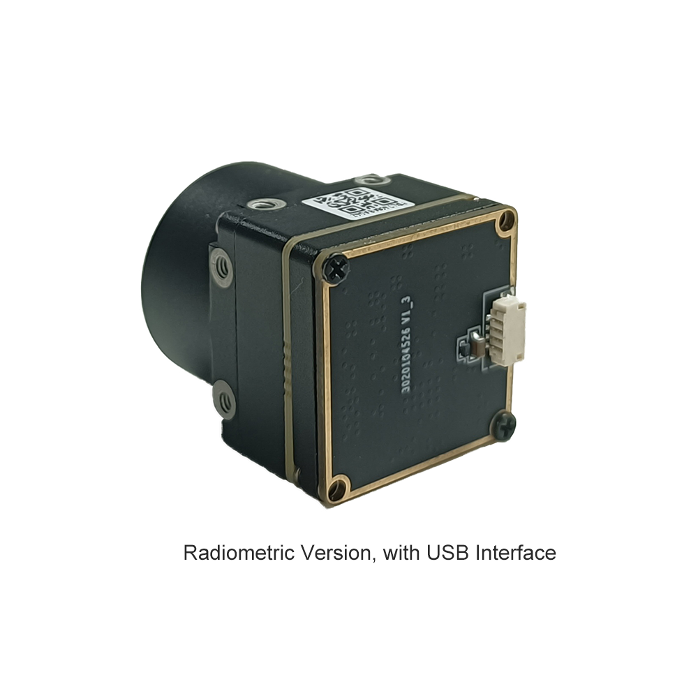
Product 1: Uncooled LWIR USB Mini 640*512 Thermal Imaging Camera Core Module For Drones Similar To DJI

This mini uncooled infrared thermal imaging module delivers sharp, detailed performance in an ultra-compact form factor. It is ideal for drone payloads and remote industrial monitoring systems.
Key Technical Specifications:
| Form Factor / Size | Ultra-miniature 21mm * 21mm footprint |
| Lens Options (Focal Length) | 5mm / 9mm / 13mm / 18mm / 35mm / 50mm / 75mm / 100mm / 150mm selections |
| Resolution Options | High-density 640x512 matrix (with 640x480 crop compatibility) |
| Integration Compatibility | Robust structural sealing, thermal stability, standard UVC compliant over USB |
Product 2: Uncooled Infrared Mipi 640 384 256 9mm Thermal Imaging Camera Module For Drones

The Mini2 series MIPI thermal imaging module streams raw thermal data with minimal latency. It is optimized for direct processing loops and lightweight aerial systems.
Key Technical Specifications:
| Primary Resolution | 640x512 active pixel matrix (with 384 and 256 structural options) |
| Default Optics | 9mm high-quality Germanium focal lens configuration |
| Hardware Interface | Direct MIPI CSI-2 signaling (optimized for minimal latency and direct hardware processing) |
| Imaging Profile | Sharp and crisp thermal image presentation, lightweight design for drones and aerial platforms |
5. Software Integration: V4L2, OpenCV, and Python SDK
Let's get our hands dirty with some code. To pull raw, uncompressed frames from a UVC thermal camera on a Raspberry Pi, we use the standard Linux Video4Linux2 (V4L2) driver.
Step 1: Check the System Properties
Before writing code, verify that the OS sees your camera. Plug the camera in and run:
# Install v4l2 utility toolkit
sudo apt-get update && sudo apt-get install -y v4l-utils

# List all connected video units
v4l2-ctl --list-devices

# Query supported resolution, formats, and frame-rate configurations
v4l2-ctl -d /dev/video0 --list-formats-ext
Look for frame formats like YDUV, YUYV, or direct 16-bit greyscale (labeled as Y16 or GREY). If your pipeline needs direct radiometric measurements, the raw 16-bit format is what you want.
Step 2: Real-World Multithreaded Python Capture
If you call VideoCapture.read() in a single-threaded Python loop, your frame rate will lag. In the shop, we run the sensor capture in a dedicated background thread to prevent blocking. This keeps the camera pipeline steady while you run heavy computer vision tasks on the main thread.
"""
RPi LWIR Thermal Acquisition and Multi-Threaded Frame Buffer Pipe
Optimized for 640x512 Uncooled USB Camera Cores.
"""

import cv2
import numpy as np
import time
import threading

class USBThermalCamera:
    def __init__(self, device_index=0, width=640, height=512):
        self.device_index = device_index
        self.width = width
        self.height = height
        self.cap = None
        self.frame = None
        self.running = False
        self.lock = threading.Lock()

    def initialize_capture(self):
        # Open video device via standard V4L2 utility backend
        self.cap = cv2.VideoCapture(self.device_index, cv2.CAP_V4L2)
        if not self.cap.isOpened():
            raise RuntimeError(f"Failed to access V4L2 sensor node: /dev/video{self.device_index}")

        # Bind payload stream resolutions to the requested parameters
        self.cap.set(cv2.CAP_PROP_FRAME_WIDTH, self.width)
        self.cap.set(cv2.CAP_PROP_FRAME_HEIGHT, self.height)

        # Verify active driver configuration values
        active_w = int(self.cap.get(cv2.CAP_PROP_FRAME_WIDTH))
        active_h = int(self.cap.get(cv2.CAP_PROP_FRAME_HEIGHT))
        print(f"[INFO] Camera pipeline running at target configuration: {active_w}x{active_h} px")

    def start_grab_thread(self):
        self.running = True
        self.thread = threading.Thread(target=self._update_loop, daemon=True)
        self.thread.start()

    def _update_loop(self):
        while self.running:
            ret, raw_frame = self.cap.read()
            if not ret or raw_frame is None:
                time.sleep(0.005)
                continue

            with self.lock:
                self.frame = raw_frame.copy()

    def grab_latest_frame(self):
        with self.lock:
            if self.frame is None:
                return None
            return self.frame.copy()

    def terminate_pipeline(self):
        self.running = False
        if hasattr(self, 'thread'):
            self.thread.join(timeout=1.0)
        if self.cap:
            self.cap.release()
        print("[INFO] Thermal core pipeline shutdown gracefully.")

if __name__ == "__main__":
    cam = USBThermalCamera(device_index=0, width=640, height=512)
    try:
        cam.initialize_capture()
        cam.start_grab_thread()
        print("[PROCESS] Streaming initialized. Press 'Q' to safely exit.")

        while True:
            frame = cam.grab_latest_frame()
            if frame is None:
                time.sleep(0.01)
                continue

            # Convert incoming YUYV channel arrays to basic greyscale structures
            gray_frame = cv2.cvtColor(frame, cv2.COLOR_BGR2GRAY)

            # Apply dynamic colormaps to visually enhance thermal variance
            # COLORMAP_INFERNO outputs excellent human eye thermography separation
            thermal_color = cv2.applyColorMap(gray_frame, cv2.COLORMAP_INFERNO)

            # Identify absolute thermal peaks within the target frame space
            min_val, max_val, min_loc, max_loc = cv2.minMaxLoc(gray_frame)

            # Draw tracking overlay representing the peak thermal zone
            cv2.circle(thermal_color, max_loc, 8, (0, 0, 255), 2)
            cv2.putText(thermal_color, f"PEAK: {max_val}", (15, 30),
                        cv2.FONT_HERSHEY_SIMPLEX, 0.6, (0, 255, 0), 2)

            cv2.imshow("LWIR 640x512 Realtime Core Pipeline", thermal_color)
            if cv2.waitKey(1) & 0xFF == ord('q'):
                break

    except Exception as err:
        print(f"[FATAL EXCEPTION]: {err}")
    finally:
        cam.terminate_pipeline()
        cv2.destroyAllWindows()
6. Advanced Image Processing: Radiometric Mapping & NUC
Raw video data is just the beginning. Setting up a professional thermal monitoring solution requires two advanced processing steps: Non-Uniformity Correction (NUC) and Radiometric Mapping.
Non-Uniformity Correction (NUC)
Because microbolometer pixels are tiny and suspended, their raw electrical properties shift over time as the camera body warms up. This drift results in a noisy, grainy image—an effect called "spatial pattern noise."
To fix this, high-performance camera cores drop a small internal mechanical shutter in front of the optical sensor for a fraction of a second. This presents a perfectly uniform thermal target to the array. The internal processor measures the raw pixel values against the average, generating an offset correction map. While our modules can run this calibration automatically, developers working with precise radiometric systems often trigger this correction manually via serial commands to avoid interruptions during critical recordings.
Radiometric Temperature Calibration
For industrial temperature measurement, you need a radiometric setup. Instead of rendering standard 8-bit visual values, the module exports a raw 16-bit integer representing the actual ADC intensity of each pixel. High-performance modules typically use a standard linear scale:
Ttarget = (Pixel Value × Scale Factor) - Offset
If your module uses a standard 0.01K scaling factor, transforming raw pixel readings into Celsius or Kelvin is straightforward:
T (Kelvin) = ADC_Pixel_Value × 0.01
T (Celsius) = (ADC_Pixel_Value × 0.01) - 273.15
In real-world applications, you must also adjust for **Target Emissivity (ε)**. This value describes how efficiently an object radiates heat compared to a theoretical blackbody (where ε = 1.0). If you are measuring polished metals like electrical copper or aluminum bushings, their emissivity can drop to 0.15 or less. This means the raw sensor will pick up ambient heat reflections rather than the actual temperature of the metal. To get accurate readings, you must adjust your post-processing math to correct for these reflections:
def calculate_absolute_temp(pixel_value, emissivity=0.95, t_ambient_k=298.15):
    # Convert standard sensor output straight to Kelvin
    t_apparent_k = pixel_value * 0.01

    # Correct for surface reflection properties
    # Object energy = (Total Energy - Reflected Ambient) / Emissivity
    t_corrected_k = ((t_apparent_k ** 4 - (1.0 - emissivity) * (t_ambient_k ** 4)) / emissivity) ** 0.25
    return t_corrected_k - 273.15
7. Industrial Field Deployments
Here's how engineers are using these integrated 640x512 microbolometer boards in field deployments:
A. UAV Aerial Inspection and Drone Mapping
By mounting these lightweight thermal cores onto small drones, utility operators can conduct automated inspections of solar farms, wind turbine blades, and high-voltage transmission lines.
Using compact setups like the Raspberry Pi Compute Module 4 (CM4), flight teams can run real-time image stabilization and target georeferencing without adding excessive weight to the airframe, preserving flight times.
B. Industrial Automation & Continuous Thermal Monitoring
Inside manufacturing plants, machinery failures can cause costly downtime. Engineers deploy Raspberry Pi boards inside sealed, industrial enclosures to continuously monitor conveyor bearings, transformers, and physical assets like boilers.
These setups watch for temperature spikes based on standard what is a thermal camera used for profiling guidelines. If a component exceeds safe limits, the Raspberry Pi can trigger alerts directly over industrial field networks using protocols like Modbus TCP or MQTT.
C. Perimeter Security and Edge Intelligence
While standard cameras struggle in complete darkness, fog, or heavy vegetation, LWIR sensors excel. Combining a high-resolution 640x512 thermal core with lightweight Edge AI models (like TFLite YOLOv8) on a Raspberry Pi 5 allows for highly reliable intruder detection. This setup can spot human silhouettes hundreds of meters away while ignoring background noise like blowing branches and wind.
If you're looking for basic hardware setups and diagnostic tools, check out our general thermal integration guide. It covers structural enclosures and protective crystal windows for harsh, dusty environments.
8. Technical Deep-Dive FAQ
Why should I upgrade from an I2C sensor like MLX90640 to a USB thermal camera module for Raspberry Pi?
Then there's the speed. I2C is a slow, serial interface. Even when overclocked, you're looking at a sluggish 4 to 8 Hz. The USB camera streams at a smooth 25 Hz over a native high-speed bus using standard UVC protocols.
Finally, there's resolution quality. Low-cost thermopile arrays suffer from high sensor noise, meaning their NETD is often around 100 mK to 150 mK. A professional VOx microbolometer core delivers an NETD ≤ 50 mK. This means you can resolve fine temperature differences down to 0.05°C, which is essential for details like tracing heat flow on circuitry or locating fluid leaks behind drywall.
How do I stream real-time thermal video on Raspberry Pi OS using your module?
uvcvideo kernel driver included in Raspberry Pi OS releases like Debian Bookworm or Bullseye. No custom drivers or kernel patches are required.
Once connected, you can capture frames directly in Python using standard OpenCV calls. To avoid lag, we recommend grabbing frames on a background thread and feeding them to your main application, where you can apply false-color maps like INFERNO or JET for clear visualization.
What is the active power consumption and thermal dissipation requirement for continuous operation?
If you're housing the camera inside a sealed enclosure or drone pod, recommend mounting it directly to an aluminum bulkhead or chassis using thermal tape or brass standoffs. Keeping the body of the module cool minimizes how often the internal NUC shutter needs to cycle, ensuring a more stable, uninterrupted video feed.
Can I perform absolute temperature measurement (radiometry) using these uncooled LWIR camera modules?
By applying our core's calibration offsets in your code, your program can convert those raw ADC values into actual Kelvin or Celsius readings in real time. Once you compensate for surface emissivity, the system delivers an absolute accuracy of within ±2°C.
📚 References & Further Reading
- ✅ Industry Standard: LightPath Technologies
- ✅ System Physical Buses: Micro Coaxial Cable Man
- ✅ Related Guide: High-Resolution 640x512 Thermal core integration





