








Best Mini Thermal Camera Module Guide: High-Res LWIR Cores for Raspberry Pi, Drones & DIY
2026年7月9日
Best LWIR Thermal Imaging Camera Module: Mini Cores for Edge AI & UAV Integration
2026年7月10日
Best 256x192 Thermal Camera Module: Integration Guide & OEM Solutions
For system integrators, drone payload designers, and optoelectronic engineers, choosing the optimal Long-Wave Infrared (LWIR) core is a balancing act of performance, cost, and physical footprint. The thermal camera module 256x192 has emerged as the definitive industry standard for applications requiring high-fidelity thermography within tight SWaP-C (Size, Weight, Power, and Cost) constraints. Unlike consumer-grade thermal dongles, industrial-grade uncooled LWIR micro-cores provide the raw pixel density and radiometric accuracy needed for autonomous navigation, industrial predictive maintenance, and precise aerial inspection.
This technical guide delivers a blueprint for selecting, integrating, and deploying 256x192 thermal cores. We dissect the underlying sensor physics, evaluate the trade-offs of microbolometer pitch, and provide a comparative analysis of top-tier industrial modules. Whether you are engineering unmanned aerial vehicles (UAVs) for defense applications or constructing stationary sub-station monitoring networks, this comprehensive guide offers the technical parameters and integration steps required to optimize your vision system.
In the shop, we often see teams overspecifying their systems, thinking they need massive, power-hungry sensors when a highly optimized microbolometer can do the job better, cooler, and for a fraction of the cost. Let's look at how to get the most out of these compact powerhouses.
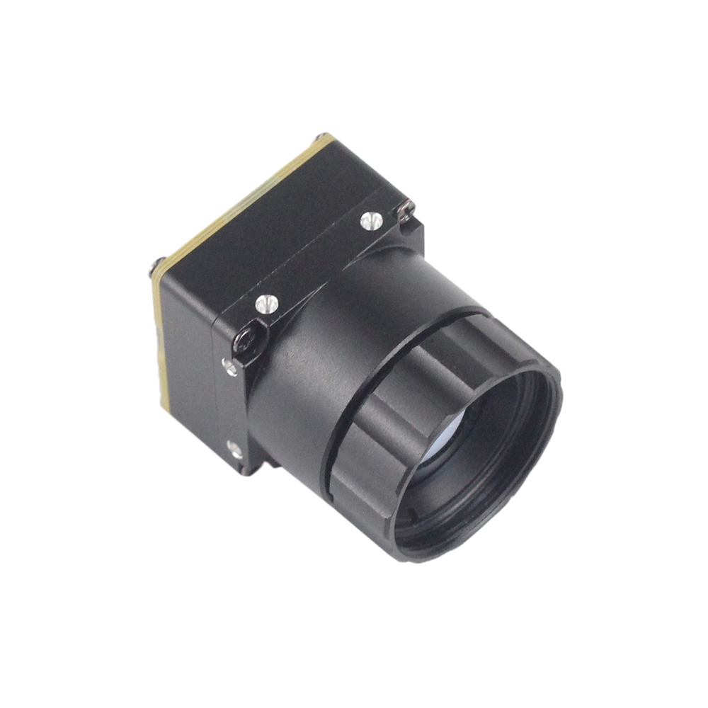
Table of Contents
1. Sensor Physics and SWaP-C Optimization
Choosing a thermographic sensor requires an understanding of uncooled VOx (Vanadium Oxide) or a-Si (Amorphous Silicon) microbolometer physics. The detector arrays inside these modules translate infrared radiation within the 8μm to 14μm wavelength block into digital values, mapping thermal energy signatures to discrete temperature measurements. When design engineers evaluate these cores, they must analyze how the microstructural design parameters affect physical packaging, image clarity, and long-term diagnostic stability.
1.1 Resolution vs. Practical Yield
A native resolution of 256x192 yields exactly 49,152 active pixels. While this may seem modest compared to mega-pixel visible-light CMOS sensors, thermal imaging operates under significantly different physical and material constraints. In the LWIR spectrum, diffraction limits are substantially larger, and the cost of raw Germanium optics scales exponentially with the physical diagnostic surface area of the focal plane array (FPA).
Comparing a 256x192 array to a legacy 160x120 array (which contains only 19,200 pixels) reveals a 2.5x increase in pixel density. This upgrade provides the spatial resolution necessary to resolve human targets at greater distances, isolate tiny structural defects, and target hot spots on dense printed circuit boards (PCBs) during validation cycles.
Here's the deal: compared to a premium 320x240 array, a 256x192 module offers an incredibly cost-effective alternative. When developers pair this array size with advanced edge digital detail enhancement (DDE) and spatial filter algorithms, a modern VOx micro-core matches the practical target-identification yield of legacy 320x240 structures while occupying less hardware space, generating less heat, and operating at a fraction of the cost.
1.2 Understanding Microbolometer Pixel Pitch
Pixel pitch—the physical distance measured from the center of one pixel to the center of the adjacent pixel—is a critical factor in thermal camera design. The industrial optoelectronics market has transitioned from legacy 17μm arrays to highly efficient 12μm microbolometer arrays. This generational leap in fabrication technology directly impacts the optical layout and packaging of modern embedded systems.
Look, the shift to a smaller 12μm pixel pitch delivers two key engineering advantages:
- ✅ Reduced Lens Diameter: Because the pixels are packed more densely, a lens with a shorter focal length can achieve the same Field of View (FOV) as a larger, heavier lens on a legacy 17μm sensor. This dramatically reduces the size and weight of the Germanium optics, which represent a massive portion of a module's manufacturing cost.
- ✅ Decreased Form Factor & Mass: Shrinking the focal plane array enables the core housing to be miniaturized down to ultra-compact footprints, such as the industry-standard 21mm * 21mm profile. This allows for seamless mechanical integration into weight-sensitive systems like micro-UAV gimbals and pocket-sized thermal devices.
1.3 Radiometry vs. Imaging-Only Sensors
When sourcing thermal cores, engineers must distinguish between imaging-only (observation) modules and radiometric modules. Selecting the wrong category can lead to major operational issues if your system requires absolute analytical data:
- ⚙️ Imaging-Only Modules: These modules apply automatic gain control (AGC) and flat-field contrast corrections across the scene to output dynamic imagery. They are optimized for human vision, target detection, and obstacle avoidance, but they do not provide absolute temperature data per pixel.
- ⚙️ Radiometric Modules: These modules perform absolute per-pixel temperature measurements. Every single pixel acts as an individual non-contact thermometer, providing a calibrated temperature reading back to the host system. This is crucial for applications such as predictive electrical grid maintenance, PCB thermal profiling, and early fire detection.
To achieve radiometric accuracy (typically ±2°C or ±2%), the core module must actively compensate for internal thermal drift. This is managed through a physical internal shutter that periodically blocks the sensor to perform a Non-Uniformity Correction (NUC), alongside integrated temperature sensors on the focal plane array. For those seeking custom solutions, exploring options like the 256 Dual Thermal and Visual Sensor Module can bridge the gap between human visualization and precise scientific measurement.
2. Hardware and Software Integration Protocols
Successfully integrating a 256x192 thermal camera module into an embedded platform requires careful consideration of physical interfaces, power management, and software communication.
2.1 Hardware Interfaces: USB vs. MIPI vs. DVP
Thermal cores typically export video and telemetry through several physical interfaces based on the application's processor architecture and driver constraints:
| Interface Type | Data Format | Typical Latency | Cable/Trace Max Length | Best Architecture Fit |
|---|---|---|---|---|
| USB 2.0 / Type-C (UVC) | Compressed MJPEG / Raw YUV / 16-bit payload | 30ms - 80ms | Up to 3 meters | Windows/Linux Single Board Computers (Raspberry Pi, Jetson Nano) |
| MIPI CSI-2 | Raw Bayer / RAW8 / RAW16 | < 10ms | < 15cm (Strict layout) | Low-power mobile APPs, high-speed RTOS processors |
| DVP (Parallel) | 8-bit or 14-bit Parallel Digital | < 5ms | < 10cm (Ultra-short RF path) | Low-cost microcontrollers, FPGA frame grabbers |
For rapid development cycles, USB (UVC-compliant) modules are incredibly easy to deploy. Because they present themselves to the host OS as standard USB video class devices, you can capture the raw thermal stream instantly without compiling proprietary kernel drivers or managing complex MIPI timing parameters.
2.2 Communication and Telemetry: UART & SPI
While UVC or MIPI handles pipeline video delivery (the visual thermal matrix), configuration commands and per-pixel radiometric arrays are typically routed over separate low-speed serial interfaces:
- ⚙️ UART (Universal Asynchronous Receiver-Transmitter): Used for host-side configuration. Over a standard 115200bps connection, the host can send hex commands to trigger a manual shutter NUC, change color palettes (e.g., White-Hot, Ironbow, Rainbow), control digital zoom, or set specific region-of-interest (ROI) emissivity coefficients.
- ⚙️ SPI (Serial Peripheral Interface): Typically used in high-speed microcontrollers to pull raw 14-bit or 16-bit radiometric frames synchronously at high master clock frequencies (up to 50 MHz). This completely bypasses the overhead of USB stacks for real-time operating systems (RTOS).
2.3 Host Processing and SDK Architecture
To convert raw outputs into actual temperature readouts, your application must process the pixel values provided by the module. Standard 14-bit digital outputs supply raw Analog-to-Digital Converter (ADC) counts, often referred to as Digital Numbers (DN).
A robust SDK converts these values using a clean, systematic flow. The raw 14-bit digital value of the pixel is multiplied by the calibration scaling slope factor (defined in the module's micro-EEPROM) and then added to the offset constant. This offset constant is adjusted automatically by the on-board processor based on the current internal temperature of the sensor, preventing measurement drift as the camera body warms up under load.
Professional integrations benefit greatly from pre-compiled libraries. Implementing projects using a comprehensive OEM thermal module integration guide provides pre-compiled C/C++, Python, and Android SDK wrappers that perform these calculations in the background. This allows your developers to query simple APIs, such as calling a single function to return the precise temperature value at specific coordinates.
3. Compare Top Industrial 256x192 & 640x512 Modules
To assist in system design and component sourcing, the section below provides a detailed comparison of our two main industrial thermal imaging modules: the ultra-compact Mini 256 and the high-resolution Mini 640.
3.1 Product Specifications Matrix
| Metric & Feature | Mini 256 Uncooled LWIR Thermal Module | Mini 640 Uncooled LWIR Thermal Module |
|---|---|---|
| Native Resolution | 256 * 192 (49,152 pixels) | 640 * 480 / 512 (Up to 327,680 pixels) |
| Detector Type | Uncooled VOx Microbolometer | Uncooled VOx Microbolometer |
| Pixel Pitch | 12μm | 12μm |
| Wavelength Range | 8μm to 14μm | 8μm to 14μm |
| NETD (Thermal Sensitivity) | < 50mK (at 25°C, F/1.0) | < 40mK (at 25°C, F/1.0) |
| Temperature Measurement Range | -20°C to +150°C (Standard); up to +550°C (Optional) | -20°C to +150°C (Standard); up to +550°C (Optional) |
| Physical Dimensions | 21mm * 21mm (Mini-Size) | 21mm * 21mm (Mini-Size) |
| Module Weight | < 15g (Super lightweight core) | < 20g (Ultra lightweight core) |
| Digital Interfaces Supported | USB 2.0 / Type-C (UVC), UART, SPI, MIPI | USB, UART, SPI, MIPI (640*480 optional) |
| Power Consumption | < 0.8W (at constant 25°C) | < 1.2W (at constant 25°C) |
| Lens Focal Lengths | 3.2mm, 6mm options standard | 5/9/13/18/35/50/75/100/150mm optional |
| Product Detail Link | Core 256 Specs | Core 640 Specs |
3.2 Deep Dive: Mini 256 LWIR Module
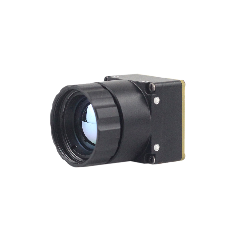
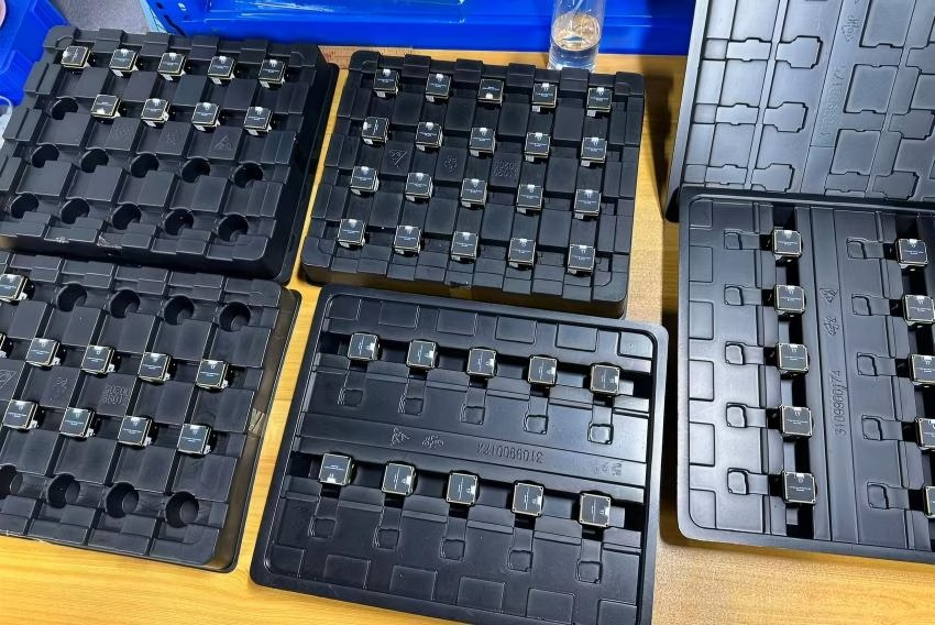
Figure 1: Mini 256 Uncooled LWIR Thermal Image Core, featuring high-aspect Radiometry & low-power design.
The Uncooled LWIR Mini 256*192 Thermal Imaging Camera Module Similar To DJI For Detecting Mines is designed for space-constrained, battery-powered applications. Weighing less than 15 grams, this core provides native 256 * 192 thermal resolution while drawing less than 0.8W of power, preserving vehicle runtime in robotic applications.
Engineered with advanced uncooled VOx microbolometer technology, it features high thermal sensitivity (<50mK) to capture clear heat maps and output a uniform thermal image with radiometry through smoke, dust, and complete darkness. It is an excellent choice for lightweight drone integration, search-and-rescue payloads, portable inspection tools, and early fire warning systems.
View Product Details & Pricing ➔
3.3 Upgrade Path: Mini 640 LWIR Module

Figure 2: Mini 640 LWIR Thermal Imaging Core Module, designed for longer range and similar to DJI payloads.
For missions requiring longer recognition ranges, such as high-altitude drone surveillance, industrial substation health mapping, or security applications, the Uncooled LWIR USB Mini 640*512 Thermal Imaging Camera Core Module For Drones Similar To DJI serves as a drop-in upgrade path.
Sharing a highly compatible 21mm * 21mm mechanical footprint, this high-performance core offers up to 640*480 optional resolution. This 6.6x increase in spatial resolution compared to the 256x192 model enables long-range target acquisition, broad-area surveillance, and detailed environmental analysis under demanding conditions. It can be paired with high-end optics from Rising Optics and drone accessories from OBSETECH.
View Product Details & Pricing ➔
4. Optical System Engineering and Lens Selection
Selecting the correct lens is critical to maximizing the performance of your 256*192 microbolometer module. The optical assembly must be matched to both the target distance and the raw pixel geometry of the uncooled array.
4.1 Chalcogenide vs. Germanium Optics
Unlike visible-light sensors that utilize standard silica optical glass, infrared wavelengths within the LWIR band (8-14μm) require specialized materials. This requires choosing between two main options:
- ⚙️ Germanium (Ge): Germanium is the gold standard for high-performance thermal imaging. It offers outstanding transmission efficiency (typically greater than 95% when optimized with anti-reflective coatings) and excellent refractive index stability over temperature. However, raw Germanium represents a significant portion of the module's overall cost.
- ⚙️ Chalcogenide Glass (GASIR): Chalcogenide optical elements can be mass-produced using glass molding techniques. This significantly lowers raw manufacturing costs, making it a popular choice for high-volume commercial thermal cores. However, it has slightly lower transmission values and is more susceptible to thermal expansion than pure Germanium.
4.2 Calculating Field of View (FOV) and DRI Ranges
To select the appropriate lens focal length for a 12μm 256x192 core, use this simplified formula to calculate the Horizontal Field of View (HFOV): where the sensor width is calculated as the number of horizontal pixels multiplied by the pixel pitch (256 * 12μm = 3.072mm). This value is then divided by twice the lens focal length, with the arc-tangent of the result multiplied by two in order to find the HFOV in degrees.
Applying this formula to typical lens options yields the following configurations:
- ✅ 3.2mm Focal Length Lens: Delivers a wide horizontal field of view of approximately 51.2 degrees. This configuration is ideal for close-range broad-area scanning, PCB diagnostics, and static room monitoring.
- ✅ 6.0mm Focal Length Lens: Delivers a narrower horizontal field of view of approximately 28.7 degrees. This configuration is optimized for medium-range target tracking and outdoor patrol applications.
Thermal range performance is categorized by Detection, Recognition, and Identification (DRI) distances, calculated based on Johnson's criteria:
- ⚙️ Detection (resolving a target at 1.5 pixels): Resolving a standard human target (1.8m * 0.5m) at up to 250 meters using a 6mm lens.
- ⚙️ Recognition (resolving a target at 6 pixels): Correctly identifying a human target at up to 62 meters using a 6mm lens.
- ⚙️ Identification (resolving a target at 12 pixels): Positive identification of a human target at up to 31 meters using a 6mm lens.
For systems that require longer detection distances (e.g., hundreds of meters), integrating a dual-sensor module, such as the 256 Dual Thermal and Visual Sensor Module, can significantly improve target verification by fusing visible and infrared channels.

5. Deep Technical FAQ
Is a 256x192 thermal resolution enough for outdoor security scanning, drone integration, and PCB inspection compared to 320x240?
Yes, absolutely. For system integrators and OEM design engineers, a 256x192 detector array represents an excellent balance of size, weight, power, and cost (SWaP-C). While a 320x240 array provides slightly higher native resolution, the incremental gain may not justify the added cost for many applications.
By utilizing advanced digital detail enhancement (DDE) and spatial filtering algorithms directly on the module's image signal processor (ISP), a modern 256x192 uncooled microbolometer can deliver clarity and structural detail comparable to legacy 320x240 systems. This performance comes at a significantly reduced unit cost, helping to lower production bills of materials (BOM).
For weight-sensitive platforms like autonomous micro-UAVs, hand-held search finders, or precise PCB thermal testing rigs, this resolution provides the necessary detail to locate thermal pathways, trace short circuits, or track human/wildlife heat signatures efficiently.
How reliable are compact thermal cores for custom Linux/Windows integration and continuous industrial operation?
In industrial software engineering, system reliability depends directly on the quality of the underlying firmware, SDK, and hardware thermal compensation. Entry-level thermal dongles often suffer from high thermal drift, freeze-ups, and sudden calibration intervals due to uncompensated internal heat building up near the focal plane array.
Our uncooled LWIR core modules are engineered for professional integration. Led by an R&D team with extensive experience in optoelectronics and chip design, these cores are built for demanding environments. They include industrial-grade SDKs with native libraries for Linux, Windows, and Android.
Additionally, we use a hard-vacuum sealed uncooled VOx microbolometer core with an automated, ultra-reliable shutter mechanism. The SDK provides structured APIs that allow for manual, automatic, or host-triggered NUCs, ensuring stable, noise-free outputs during continuous operation in environments ranging from -20°C to +60°C.
Can these mini 256x192 thermal modules handle absolute radiometric temperature measurement?
Our thermal camera modules are fully radiometric cores. Each pixel on the 256x192 array captures independent thermal radiation and converts it into temperature values in degrees Celsius or Kelvin. The sensor does not just produce a visual representation of temperature gradients; it outputs a detailed matrix of per-pixel temperature measurements.
This capability is essential for critical automated monitoring networks, such as substation overload tracking, data center server inspections, conveyor belt friction monitoring, and early fire warning systems. To maintain measurement accuracy (±2°C or ±2%) across varying ambient conditions, the firmware monitors internal board-mounted thermistors.
The core automatically compensates for changes in ambient temperature by updating the correction offset applied to the raw ADC counts. This maintains consistent accuracy without requiring manual recalibration in the field.
📚 References & Further Reading
- Industry Standard: Rising Optics Optoelectronic Lens Design
- Partner Drone Solutions: OBSETECH Unmanned Aerial Systems
- Related Guide: 2025 Thermal Module Architectural Integration Guide
- Our Engineering Portal: About Thermal-Type.com & Custom Sourcing





