








Custom Thermal Imaging Module ODM: High-Performance LWIR Cores & Edge AI Integration
2026年9月4日
Custom Infrared Camera Core: High-Resolution OEM Thermal Imaging Solutions
2026年9月7日
Thermal Module SDK for Integration: Developer Guide for Embedded AI & Radiometry
Engineering Hook
Look, integrating long-wave infrared (LWIR) focal plane arrays into autonomous robotics, uncrewed aerial systems (UAS), and high-speed industrial inspection rigs is a completely different beast than hooking up a standard visible-light webcam. Out in the shop, we constantly see embedded vision engineers and firmware architects run headfirst into serious performance walls. They hook up an uncooled Vanadium Oxide (VOx) microbolometer over a basic USB pipe, expect butter-smooth frames, and immediately hit crippling transport latency, dropped frames during Non-Uniformity Correction (NUC) shutter calibration cycles, and memory bus choking. Worse yet, generic USB Video Class (UVC) drivers will happily crush critical 14-bit or 16-bit radiometric values into stripped-down 8-bit visual junk, wrecking downstream edge artificial intelligence inference before the model even sees the frame.
Here's the deal: a purpose-built thermal module SDK for integration isn't an optional convenience library—it is the mission-critical software bridge in your system stack. It binds raw sensor registers and low-level digital count pickoffs directly to modern parallel compute environments like NVIDIA TensorRT, OpenCV, and ROS 2. By delivering deterministic programmatic control over sensor register maps, real-time Planck temperature conversion, spatial noise filter parameters, and dynamic calibration offsets, a production-grade SDK allows engineering teams to pull clean radiometric telemetry straight off the silicon and feed edge AI models without melting their CPU budgets.
Table of Contents
- 👉 1. Architectural Overview: Decoupling Hardware Control, Raw Streams, and Processing
- 👉 2. Physical Layer and Embedded Bus Architecture (USB-C, MIPI-CSI, UART/SPI)
- 👉 3. Radiometric Calibration Mathematics, Planck Formulations, and Sensor Ingestion
- 👉 4. Zero-Copy Memory Pipelines for Embedded Edge AI Acceleration
- 👉 5. Production Hardware Profiles: Comparing Mini 640 and Mini 384 Cores
- 👉 6. Concrete Implementation Blueprint: C++ & Python Raw Extraction
- 👉 7. Thermal Drift, Shutter Latency Mitigation, and NETD Tuning
- 👉 8. Comprehensive Engineering FAQ
1. Architectural Overview: Decoupling Hardware Control, Raw Streams, and Processing
In legacy monolithic camera libraries, display rendering functions—like automatic gain control (AGC), histogram equalization, and pseudo-color palette lookups—are hardwired directly into the frame capture loop. On a benchtop test PC with cycles to burn, that might look fine. But in a resource-constrained embedded build, it's an absolute disaster. The moment an AGC display loop stutters or fights for thread execution, your frame capture thread stalls. The result? Buffer overflows, dropped frames, and broken sensor synchronization.
A battle-tested SDK avoids this trap by isolating low-level hardware communication from the compute pipeline. It uses an asynchronous, two-pronged pipeline model that splits operations into dedicated functional channels:
Key Architectural Paths:
- ⚙️ The Telemetry and Control Plane: Manages bidirectional device settings via asynchronous remote procedure calls (RPC) or deterministic register read/write sequences over USB Control Endpoints (EP0), native serial UART, I2C, or high-speed SPI. This path governs lens focus positions, high/low gain switching, NUC shutter triggers, ambient emissivity offsets, and sensor die thermistor readouts without touching the pixel stream.
- ⚙️ The Isochronous and Bulk Data Streaming Plane: Engineered exclusively for high-throughput frame transport of uncompressed raw digital counts or factory-calibrated radiometric tensors. This channel utilizes USB bulk/isochronous endpoints, direct MIPI CSI-2 virtual lanes, or parallel CMOS/LVDS links to pipe pixel streams directly into physical system memory without stalling control transactions.
Under this architecture, the ingestion pipeline splits incoming data straight at the driver boundary. Your primary inference worker thread pulls pristine, uncompressed 14-bit (Y14) or packed 16-bit (Y16) digital values, preserving genuine radiometric fidelity for critical computer vision calculations. In parallel, a lightweight worker thread can run Plateau Histogram Equalization (PHE) or Linear Percentile Mapping to feed an 8-bit monitor stream for human operators on an inspection floor or ground control station.
This strict boundary ensures that whatever color adjustments, AGC curves, or display tweaks you apply for human eyes never compromise or alter the physical temperature arrays needed by autonomous flight computers, safety interlocks, or defect detection algorithms.
2. Physical Layer and Embedded Bus Architecture (USB-C, MIPI-CSI, UART/SPI)
Choosing your physical hardware interconnect isn't just a benchtop wiring decision; it sets the boundary conditions for your entire embedded vision pipeline. High-vibration platforms—like industrial inspection UAVs, ground robotics traversing rough terrain, and high-speed pick-and-place end effectors—demand minimal harness mass, mechanically robust connectors, and rock-solid signal integrity.
USB 2.0 / USB-C Interfacing via UVC Extension Units
USB-C is the standard go-to for rapid integration on edge carrier boards and x86/ARM host modules. Because it complies with the USB Video Class (UVC 1.1/1.5) standard, the camera initializes natively across modern operating systems without needing flaky third-party kernel drivers. Radiometric feeds are transported through custom pixel formats identified by standard FourCC identifiers such as Y16 , YUYV, or custom vendor streaming descriptors.
Here is where amateur designs stumble: many engineers wire up an auxiliary USB-to-UART bridging chip just to pass control commands down to the core. That's a waste of bill-of-materials cost and circuit board real estate. A properly engineered thermal SDK communicates via UVC Extension Units (XU) right across USB Control Endpoint 0 (EP0). By wrapping register queries, shutter actuations, and lookup table writes inside native UVC control transfers, you cut out extra bridging silicon, free up board space, and eliminate another potential point of hardware failure.
MIPI CSI-2 and Parallel Digital Interconnects
When you are building micro-gimbals or battery-powered sensor nodes where every gram and milliwatt counts, USB host controller overhead becomes a liability. That is where direct MIPI CSI-2 (Camera Serial Interface) routing wins hands down. Running through micro-coaxial or flexible printed circuit (FPC) assemblies—like those manufactured by Molex—a MIPI interface links the sensor Readout Integrated Circuit (ROIC) directly to the host processor's Image Signal Processor (ISP) or Video Input (VI) subsystem.
- ⚙️ Direct Hardware DMA Pipelines: MIPI CSI-2 bypasses host USB controllers entirely, using Direct Memory Access (DMA) to stream raw frame data straight into system RAM with near-zero CPU intervention or kernel scheduling jitter.
- ⚙️ Sub-Microsecond Clock Synchronization: Hardware MIPI connections can be tied directly to hardware sync pins, like an external Pulse-Per-Second (PPS) line or IMU trigger. This guarantees frame-level synchronization between your thermal stream, visible RGB cameras, and LiDAR point clouds.
- ⚙️ Low-Overhead Control Buses: With MIPI handling raw pixels, camera control moves to an auxiliary high-speed SPI bus running up to 50 MHz or a reliable I2C Camera Control Interface (CCI) channel.
If you are weighing interface options across real-world carrier boards, be sure to study our 2025 thermal module guide for low-cost fast integration.
3. Radiometric Calibration Mathematics, Planck Formulations, and Sensor Ingestion
Let's clear up a common misconception: an uncooled microbolometer does not output a direct temperature reading. Infrared radiation passing through the lens hits miniature Vanadium Oxide membranes suspended over silicon ROIC cavities. That absorbed energy changes the material's electrical resistance. The ROIC samples those shifts as analog voltages and digitizes them into raw 14-bit or 16-bit unsigned integers, universally known as Digital Numbers (DN). Transforming those raw counts into verified engineering units demands a solid grasp of infrared imaging physics.
The Inverted Planck Radiation Equation
To convert raw digital numbers ($DN$) into absolute temperatures in Kelvin ($T_{obj}$), the SDK isolates the object's actual emitted flux and evaluates an inverted, empirical curve of Planck's Radiation Law:
The variables B, R, and F represent sensor-specific calibration constants established on an automated blackbody calibration rig at the factory and stored in the camera's onboard non-volatile memory. The term S_obj is the radiant flux coming strictly from the target object, isolated from background ambient reflections and atmospheric attenuation.
Compensating for Environmental and Optical Variables
In real-world environments, the total infrared flux hitting the microbolometer array ($S_{total}$) is an aggregate of three distinct radiative inputs:
- ⚙️ The target's direct thermal emission, determined by its surface emissivity ($\varepsilon$) and attenuated by atmospheric transmission ($\tau_{atm}$).
- ⚙️ Diffuse environmental reflections bouncing off the target, scaled by reflectivity $(1 - \varepsilon)$ and atmospheric path transmission ($\tau_{atm}$).
- ⚙️ Stray infrared energy emitted by the air column itself between the lens and the target, proportional to $(1 - \tau_{atm})$.
Putting that together into the comprehensive radiometric flux equation:
A reliable industrial SDK handles these conversions behind the scenes. Leveraging SIMD instructions (like ARM NEON on Cortex-A cores or AVX2 on x86 chips), it transforms raw 16-bit integer frames into full floating-point temperature matrices in real time. You inject live atmospheric parameters—target emissivity, ambient reflected temperature, target distance, and relative humidity—and the SDK dynamically recalculates the output array on the fly.
To match the right sensor hardware with your application constraints, review our uncooled VOx thermal module selection guide for Edge AI.
4. Zero-Copy Memory Pipelines for Embedded Edge AI Acceleration
Deploying convolutional neural nets or vision transformers on edge targets like the NVIDIA Jetson Orin Nano, Jetson AGX Orin, Rockchip RK3588, or Raspberry Pi 5 comes down to one thing: keeping the memory bus clear. The most common mistake we see in thermal vision pipelines is redundant buffer copies between driver space, user memory, and machine learning runtime contexts.
Consider the standard, inefficient pipeline: the Linux V4L2 driver dumps a frame into memory-mapped buffers, the application deep-copies that memory into a user-space buffer, wraps it into a standard OpenCV cv::Mat, and then pushes it across PCIe into CUDA unified memory. That constant copying burns CPU cycles, drives up cache misses, and drives latency through the roof.
Here is how a high-performance thermal SDK builds a streamlined, zero-copy pipeline:
-
✅ Kernel Ingestion via DMA-BUF: Rather than allocating separate user-space arrays, the SDK takes memory-mapped V4L2 buffers (
V4L2_MEMORY_MMAP) and exports them directly as standardDMA-BUFfile descriptors. -
✅ Direct Hardware Unified Memory Mapping: By handing these
DMA-BUFfile descriptors straight to platform-specific APIs (like NVIDIA'sNvBufferor unified memory spaces), the incoming thermal frame is instantly addressable by the GPU, DLA, or ISP without touching the CPU. - ✅ Hardware-Accelerated Dynamic Range Compression: When you need to feed conventional 3-channel networks (like YOLOv8 or MobileNet), conversion from 14-bit radiometric counts to 8-bit dynamic range is offloaded directly to custom CUDA kernels or hardware ISP blocks, sidestepping CPU thread bottlenecks entirely.
-
✅ Parallel Tensor & Radiometric Evaluation: Raw 16-bit frame pointers are mapped directly into CUDA memory surfaces (such as
cudaSurfaceObject_torcv::cuda::GpuMat). Your system can execute deep-learning object classification while simultaneously running pixel-level threshold checks across raw thermal data—maintaining full 50 Hz frame rates without thermal throttling.
5. Production Hardware Profiles: Comparing Mini 640 and Mini 384 Cores
Your physical sensor core establishes the baseline limits for spatial detail, optical reach, and compute demands. Below is a side-by-side engineering breakdown of two production-ready uncooled LWIR camera modules fully supported by this SDK architecture.
Mini 640 vs. Mini 384 Core Comparison
| Technical Parameter | Mini 640 LWIR Camera Core Module | Mini 384 LWIR Camera Core Module |
|---|---|---|
| Detector Architecture | Uncooled VOx (Vanadium Oxide) Microbolometer | Uncooled VOx (Vanadium Oxide) Microbolometer |
| Array Resolution | 640 × 512 pixels (640 × 480 selectable) | 384 × 288 pixels |
| Pixel Pitch | 12 μm | 12 μm |
| Spectral Band | 8 μm to 14 μm (LWIR) | 8 μm to 14 μm (LWIR) |
| NETD (Thermal Sensitivity) | ≤ 40 mK (@ f/1.0, 300K, 25Hz) | ≤ 40 mK (@ f/1.0, 300K, 25Hz) |
| Frame Rate Profiles | 25 Hz / 30 Hz / 50 Hz | 25 Hz / 30 Hz / 50 Hz |
| Available Focal Lengths | 5 / 9 / 13 / 18 / 35 / 50 / 75 / 100 / 150 mm | Standard Athermalized & Motorized Lens Series |
| Module Dimensions | 21 mm × 21 mm base enclosure | Ultra-compact footprint for micro-payloads |
| Electrical Interfaces | USB-C (UVC + Direct Command XU), UART, Digital LVDS | CVBS (Analog), USB (UVC), UART, SPI |
| SDK Data Output Modes | Raw 14-bit / 16-bit Y14/Y16 + Parallel 8-bit AGC Stream | Raw 14-bit Radiometric Stream + 8-bit Display Stream |
| Temperature Measurement | -20°C to +150°C (High Gain); 0°C to +550°C (Low Gain) | -20°C to +150°C; Up to +650°C Custom Calibration |
| Application Focus | Long-range search & rescue, drone payloads, gas imaging | Robotics, predictive equipment maintenance, compact sUAVs |
Detailed Core Profiles
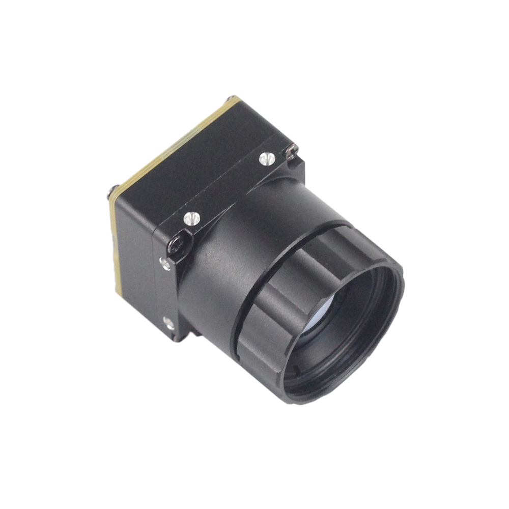
Uncooled LWIR USB Mini 640*512 Thermal Imaging Camera Core Module
The Mini 640 is an industrial powerhouse designed specifically for applications demanding dense pixel counts inside an ultra-compact 21mm × 21mm envelope. Pushing a native 640×512 resolution (with a software-selectable 640×480 crop mode via register), this core is built for aerial reconnaissance gimbals, perimeter security systems, and high-precision infrastructure inspection.
With a 12μm pixel pitch, this module resolves fine thermal gradients at substantial standoff ranges when paired with long-focus Germanium optics (from 5mm up to 150mm). Its single USB-C pipeline simultaneously delivers clean, uncompressed 14-bit/16-bit radiometric frames alongside register control through UVC Extension Units, making it an ideal choice when payload volume and gimbal balance are top priorities.

Uncooled Mini 384*288 Thermal Camera Module For Drones
The Mini 384 is the workhorse option for tight SWaP-C (Size, Weight, Power, and Cost) budgets. Built around an uncooled 384×288 VOx microbolometer array with an identical 12μm pitch and ≤40 mK thermal sensitivity, it strikes an optimal balance between low electrical load, minimal weight, and high radiometric performance.
What sets the Mini 384 apart in the field is its versatile interface set. It outputs analog CVBS video to link directly with legacy 5.8 GHz analog drone transmitters, while running standard USB-C UVC and serial SPI/UART interfaces for digital compute boards. It supports broad dual-gain temperature spans from -20°C up to +650°C, making it a reliable pick for electrical cabinet inspection, UAV search tasks, and predictive facility maintenance.
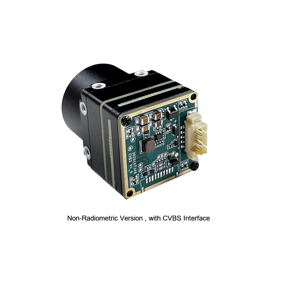
For detailed connector pin maps, mechanical mounting patterns, and driver configuration steps, check out our 384x288 thermal camera core integration manual.
6. Concrete Implementation Blueprint: C++ & Python Raw Extraction
Let's look at working code. Below are production-ready blueprints in both modern C++ and Python showing how to ingest a raw 16-bit radiometric stream and convert Digital Numbers (DN) into calibrated Celsius arrays without getting bogged down in user-space copy bottlenecks.
C++ Production Ingestion Engine
This C++ implementation targets the Linux Video4Linux2 (V4L2) backend in OpenCV, locking the capture node into raw 16-bit integer extraction mode (Y16 ) and executing the inverted Planck transformation:
#include <iostream>
#include <vector>
#include <cmath>
#include <opencv2/opencv.hpp>

// Factory-calibrated Planck coefficients (extracted from sensor EEPROM)
constexpr float SENSOR_PLANCK_B = 1428.0f;
constexpr float SENSOR_PLANCK_F = 1.0f;
constexpr float SENSOR_PLANCK_R = 224056.0f;

class ThermalCorePipeline {
public:
    explicit ThermalCorePipeline(int deviceIndex) {
        // Open the thermal core through standard Linux V4L2 capture
        captureNode.open(deviceIndex, cv::CAP_V4L2);
        if (!captureNode.isOpened()) {
            throw std::runtime_error("Sensor capture initialization failed: device node inaccessible.");
        }

        // Set FourCC to raw 16-bit linear integer stream (Y16)
        captureNode.set(cv::CAP_PROP_FOURCC, cv::VideoWriter::fourcc('Y', '1', '6', ' '));
        captureNode.set(cv::CAP_PROP_FRAME_WIDTH, 640);
        captureNode.set(cv::CAP_PROP_FRAME_HEIGHT, 512);
        captureNode.set(cv::CAP_PROP_CONVERT_RGB, false); // Preserve raw byte structures
    }

    // Convert raw 16-bit digital values to calibrated Celsius temperatures
    cv::Mat ExtractCelsiusMatrix(const cv::Mat& rawFrame, float emissivity = 0.97f) {
        cv::Mat celsiusMatrix(rawFrame.rows, rawFrame.cols, CV_32FC1);

        for (int row = 0; row < rawFrame.rows; ++row) {
            const uint16_t* rawDataPtr = rawFrame.ptr<uint16_t>(row);
            float* outputDataPtr = celsiusMatrix.ptr<float>(row);

            for (int col = 0; col < rawFrame.cols; ++col) {
                // Mask the 14-bit digital value, discarding ROIC telemetry flags
                uint16_t rawCount = rawDataPtr[col] & 0x3FFF;

                // Scale target flux using the target's emissivity coefficient
                float targetFlux = static_cast<float>(rawCount) / emissivity;

                // Invert the Planck equation to derive Kelvin temperature
                float kelvin = SENSOR_PLANCK_B / std::log((SENSOR_PLANCK_R / targetFlux) + SENSOR_PLANCK_F);

                // Convert Kelvin to Celsius
                outputDataPtr[col] = kelvin - 273.15f;
            }
        }
        return celsiusMatrix;
    }

    void ProcessNextFrame() {
        cv::Mat rawFrame;
        if (captureNode.read(rawFrame)) {
            cv::Mat calibratedCelsius = ExtractCelsiusMatrix(rawFrame);

            // Sample a 3x3 pixel area at the image center
            cv::Rect centerRegion(319, 255, 3, 3);
            cv::Scalar meanTemp = cv::mean(calibratedCelsius(centerRegion));

            std::cout << "[TELEMETRY] Central Region Temperature: "
                      << meanTemp[0] << " C" << std::endl;
        }
    }

    ~ThermalCorePipeline() {
        if (captureNode.isOpened()) {
            captureNode.release();
        }
    }

private:
    cv::VideoCapture captureNode;
};

int main() {
    try {
        ThermalCorePipeline pipeline(0);
        for (int i = 0; i < 30; ++i) {
            pipeline.ProcessNextFrame();
        }
    } catch (const std::exception& ex) {
        std::cerr << "Execution Fault: " << ex.what() << std::endl;
        return -1;
    }
    return 0;
}
Python Edge Radiometry Pipeline
For Python-centric setups, loop iteration is a performance killer. This script uses vectorized NumPy operations across the raw frame buffer to convert raw counts into temperature tensors at line rate:
import cv2
import numpy as np

def run_edge_radiometry_pipeline(device_id=0):
    # Initialize hardware capture node via Linux V4L2
    cap = cv2.VideoCapture(device_id, cv2.CAP_V4L2)

    # Request raw 16-bit radiometric transmission format (Y16)
    cap.set(cv2.CAP_PROP_FOURCC, cv2.VideoWriter_fourcc(*'Y16 '))
    cap.set(cv2.CAP_PROP_FRAME_WIDTH, 640)
    cap.set(cv2.CAP_PROP_FRAME_HEIGHT, 512)
    cap.set(cv2.CAP_PROP_CONVERT_RGB, 0)

    # Core calibration coefficients
    PLANCK_B = 1428.0
    PLANCK_F = 1.0
    PLANCK_R = 224056.0
    SURFACE_EMISSIVITY = 0.95

    try:
        while True:
            success, raw_buffer = cap.read()
            if not success or raw_buffer is None:
                print("Failed to acquire frame buffer from sensor core.")
                break

            # Mask status bits to isolate pure 14-bit digital numbers (DN)
            raw_counts = np.bitwise_and(raw_buffer, 0x3FFF).astype(np.float32)

            # Vectorized Planck inversion across the full sensor array
            adjusted_flux = raw_counts / SURFACE_EMISSIVITY
            kelvin_matrix = PLANCK_B / np.log((PLANCK_R / np.maximum(adjusted_flux, 1.0)) + PLANCK_F)
            celsius_matrix = kelvin_matrix - 273.15

            # Extract scene metrics
            peak_temp = np.max(celsius_matrix)
            mean_temp = np.mean(celsius_matrix)
            print(f"[EDGE TELEMETRY] Max Temp: {peak_temp:.2f} C | Mean Temp: {mean_temp:.2f} C")

            # Generate dynamic 8-bit visualization for monitoring
            norm_visual = cv2.normalize(celsius_matrix, None, 0, 255, cv2.NORM_MINMAX, dtype=cv2.CV_8U)
            colormap_preview = cv2.applyColorMap(norm_visual, cv2.COLORMAP_INFERNO)

            cv2.imshow("LWIR Radiometric Monitor", colormap_preview)
            if cv2.waitKey(1) & 0xFF == ord('q'):
                break
    finally:
        cap.release()
        cv2.destroyAllWindows()

if __name__ == "__main__":
    run_edge_radiometry_pipeline()
7. Thermal Drift, Shutter Latency Mitigation, and NETD Tuning
In clean bench tests, thermal cameras look fantastic. But once you mount a module inside an enclosed carbon-fiber drone airframe or right next to an industrial servo drive, thermal drift becomes your number one problem. Because uncooled microbolometers do not have active cryogenic chillers, the sensor die continually exchanges thermal energy with the camera housing, optics, and nearby circuitry.
Mitigating Shutter Latency and Image Freezing
To re-zero pixel offset baselines, an uncooled core triggers an automated Non-Uniformity Correction (NUC). An internal solenoid snaps a mechanical shutter flag in front of the microbolometer array for 250 to 500 milliseconds. Every pixel samples this uniform thermal target, recalibrating individual offset coefficients.
The catch? During those 500 milliseconds, the video stream halts completely. If your drone is on a final autonomous descent vector or your ground robot is maneuvering around obstacles at speed, that sudden half-second visual blackout can cause state estimation drift or break visual feature tracking entirely.
Here is how we handle shutter latency out in the real world:
-
⚙️ Programmatic Shutter Locks: Turn off automatic background NUC cycles entirely by writing
SET_NUC_AUTO_MODE = 0via the SDK control interface. This puts the host software in control, allowing your flight computer to trigger a calibration pulse only during safe operational windows—such as stationary hovers or waypoints between inspection runs. - ⚙️ Shutterless Algorithmic Drift Compensation: For critical systems that cannot tolerate any blind spots, deploy shutterless correction modes. The SDK reads onboard thermistors on the lens cell and ROIC substrate, using a dynamic polynomial model to mathematically predict and zero out thermal drift across the array without ever dropping the mechanical shutter flag.
Optimizing Noise Equivalent Temperature Difference (NETD)
Noise Equivalent Temperature Difference (NETD) measures the smallest temperature delta the sensor can pull out of background noise. Both the Mini 640 and Mini 384 boast ratings of ≤40 mK in laboratory tests. But poor electrical and mechanical integration on a host carrier board can easily blow that out to a noisy 80 mK.
- ✅ Clean Carrier Board Power Delivery: High-frequency switching noise on 3.3V or 5V power rails readily injects noise into sensitive ROIC analog-to-digital converters. Feed the camera module from dedicated Low-Dropout (LDO) regulators, and keep high-frequency ripple below 15 mV RMS.
- ✅ Tuning Temporal Filter Coefficients: The SDK integrates configurable Infinite Impulse Response (IIR) and spatio-temporal recursive noise filters. Enabling these blocks cleans up high-frequency thermal noise across successive frames without blurring fast-moving targets across the field of view.

8. Comprehensive Engineering FAQ
How does the thermal module SDK handle raw radiometric data extraction for accurate temperature analysis?
What platforms and hardware interfaces are supported for drone and embedded vision integration?
Can the thermal SDK execute Edge AI inference without causing high latency or CPU bottlenecks?
What is the mechanical shutter impact during real-time flight control, and how does the SDK bypass it?
📚 References & Further Reading
- Industry Standard: Wikipedia Infrared Imaging Physics & Bolometer Design
- Hardware Interconnects: Molex Micro-Miniature Interconnect Systems for Edge Devices
- Related Integration Guide: Complete 384x288 Thermal Camera Core Hardware Integration Guide
- Procurement Guide: Uncooled VOx Edge AI OEM Thermal Module Selection & Purchase Guide
- Architecture Review: 2025 Thermal Module Guide: Low-Cost Fast Integration for Engineers





