USB Thermal Camera Module 640x512: Compact LWIR Core for Embedded & Drone Vision
2026年9月18日
Industrial USB Thermal Camera Core: Compact LWIR OEM Modules for Embedded Vision & Inspection
2026年9月20日
USB Thermal Imaging Sensor Module Guide: High-Res LWIR Integration for Edge AI & SBCs
Modern machine vision systems, autonomous aerial platforms, and edge compute clusters require robust thermal perception beyond the visible light spectrum. While standard optical sensors rely on ambient illumination and surface reflectivity, uncooled Long-Wave Infrared (LWIR) microbolometers measure radiation directly emitted by objects in the 8 µm to 14 µm spectral band. Integrating a usb thermal imaging sensor module directly into industrial Linux gateways, field inspection drones, and single-board computers (SBCs) eliminates the legacy dependency on bulky analog video decoders, proprietary frame grabbers, and custom bridge boards.
Deploying high-resolution LWIR cores via standardized USB interfaces introduces distinct engineering considerations: thermal dissipation within tight enclosures, Non-Uniformity Correction (NUC) drift compensation, Video4Linux2 (V4L2) driver compatibility, raw 14-bit/16-bit radiometric array extraction, and strict Size, Weight, Power, and Cost (SWaP-C) constraints. This technical guide outlines the optical, electrical, and firmware requirements needed to successfully integrate an uncooled usb thermal imaging sensor module into edge processing platforms—such as the Raspberry Pi, NVIDIA Jetson, and x86 embedded computers—transitioning your hardware pipeline from low-accuracy thermopiles to calibrated, industrial-grade radiometric vision.
Table of Contents
- 👉 1. Uncooled LWIR Fundamentals: Microbolometers vs. Thermopile Arrays
- 👉 2. Hardware Architecture: Core Electronics, ISP, and USB Engine
- 👉 3. Protocols and Driver Integration: UVC Video vs. 14-Bit Radiometric Feeds
- 👉 4. Edge AI & Single-Board Computer Implementation (Raspberry Pi & Jetson)
- 👉 5. Product Showcase: Real-World Specifications Comparison
- 👉 6. Thermal Optics Selection & Detection Range Calculation
- 👉 7. Industrial Applications: Unmanned Platforms, Machine Vision, and Security
- 👉 8. Deep-Dive Engineering FAQ
1. Uncooled LWIR Fundamentals: Microbolometers vs. Thermopile Arrays
Infrared thermal sensing within industrial automation and embedded systems generally splits into two fundamental categories: low-cost thermopile arrays and uncooled focal plane array (FPA) microbolometers. For basic presence detection or rudimentary thermal mapping, entry-level thermopiles (such as the Melexis MLX90640 or Omron D6T series) offer matrices ranging from 16×4 up to 32×24 pixels. However, thermopile sensors rely on the Seebeck effect across microscopic serial thermocouple junctions. Because they measure the physical thermal gradient established across cold and hot junctions without dedicated vacuum insulation, thermopiles suffer from high thermal noise, slow thermal time constants exceeding 100 ms, substantial pixel cross-talk, and severe susceptibility to ambient temperature shifts.
In contrast, a high-performance usb thermal imaging sensor module utilizes a vacuum-packaged Focal Plane Array composed of microbolometers. Each individual microbolometer pixel consists of an infrared-absorber membrane suspended over an underlying silicon substrate by micro-machined silicon nitride support legs. Underneath the absorber membrane lies an integrated Read-Out Integrated Circuit (ROIC). The entire micro-electro-mechanical system (MEMS) structure is enclosed in a permanent wafer-level high-vacuum package (WLP) or metal-can vacuum package to eliminate convective thermal heat dissipation into surrounding gases.
When incident electromagnetic radiation in the Long-Wave Infrared spectrum (typically 8 µm to 14 µm) strikes the microbolometer absorber plate, the absorbed photonic energy heats the active material. This minute temperature elevation alters the electrical resistance of the thin-film layer. The active layer is predominantly fabricated using Vanadium Oxide (VOx) or amorphous Silicon (a-Si). Vanadium Oxide is the industrial standard due to its high Temperature Coefficient of Resistance (TCR), typically ranging from -2% to -3% per Kelvin, combined with significantly lower 1/f flicker noise compared to amorphous silicon alternatives.
| Architectural Parameter | Thermopile Array (e.g., 32×24) | VOx Uncooled Microbolometer Core |
|---|---|---|
| Spatial Resolution | 768 pixels (32 × 24) to ~4,960 pixels | 49,152 (256×192) up to 327,680 (640×512) pixels |
| Thermal Sensitivity (NETD) | 100 mK to 150 mK | < 40 mK to < 50 mK (f/1.0 at 300 K) |
| Pixel Pitch | ~90 µm to 120 µm | 12 µm (High-density wafer level) |
| Frame Refresh Rate | 2 Hz to 16 Hz (limited by thermal time constant) | 25 Hz to 50 Hz (Real-time fluid motion) |
| Thermal Time Constant (τ) | 30 ms to 100 ms | 8 ms to 12 ms |
| Primary Failure Mode | Spatial blur, severe sensor temperature drift | Requires periodic NUC shuttering if uncorrected |
The ROIC reads resistance variations by applying a pulsed electrical bias to the microbolometer bridge network. High-speed integrators convert the resulting current differentials into digital voltage values via on-chip analog-to-digital converters (ADCs), outputting raw 14-bit or 16-bit digital counts. For systems integrators designing automated fault detection, choosing between microbolometers and lower-tier sensors is clear: when high spatial resolution, low Noise Equivalent Temperature Difference (NETD < 40 mK), and rapid optical response are mandatory, a calibrated VOx core is indispensable. To explore these sensor mechanics in greater detail, consult our comprehensive analysis on how to choose an infrared thermal camera core for demanding field deployments.
2. Hardware Architecture: Core Electronics, ISP, and USB Engine
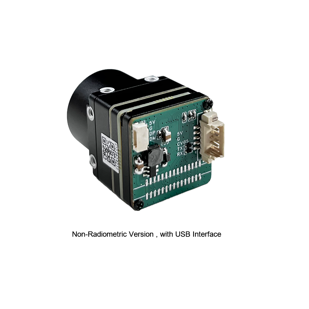
An industrial-grade usb thermal imaging sensor module integrates multiple advanced hardware blocks within an ultra-miniature footprint (down to 21 mm × 21 mm). It transitions photonic thermal signals into a clean, digital serial bus output through several tightly coupled subsystems:
- ⚙️ Optomechanical Subsystem: Precision-machined housing containing high-transmission monocrystalline Germanium or chalcogenide glass optics, paired with an integrated electromechanical solenoid shutter flag.
- ⚙️ Vacuum-Packaged FPA and ROIC: The 12 µm VOx pixel array mated directly to the silicon read-out IC, operating at wafer-level hermetic vacuum to maintain thermal isolation.
- ⚙️ Field-Programmable Gate Array (FPGA) or ASIC Image Signal Processor (ISP): The onboard embedded processor tasked with executing high-speed, mathematically intensive calibration, spatial filtering, and dynamic range mapping algorithms.
- ⚙️ USB Bridge Controller: High-speed USB 2.0 or USB 3.x PHY and controller supporting standard USB Video Class (UVC), USB Communications Device Class (CDC), or Human Interface Device (HID) vendor endpoints.
The onboard ISP is the computational engine of the module. Raw microbolometer data cannot be sent straight to a display or deep-learning classifier because each pixel suffers from manufacturing non-uniformities. Microscopic variations in leg width, absorber thickness, and contact resistance cause Fixed-Pattern Noise (FPN) that can completely obscure true thermal targets. To solve this, the ISP processes every frame through a four-stage real-time pipeline:
1. Two-Point Non-Uniformity Correction (NUC): Gain and offset correction tables are stored in non-volatile flash memory on the core. The ISP maps incoming raw digital counts ($S_{i,j}$) through individualized coefficient arrays according to the formula:
S'_{i,j} = G_{i,j} \times (S_{i,j} - O_{i,j})
Where $G_{i,j}$ represents the pixel-specific gain coefficient and $O_{i,j}$ represents the offset coefficient calculated during factory calibration across multiple blackbody temperatures.
2. Bad Pixel Replacement (BPR): Pixels that exhibit zero electrical response, excessive dark current, or continuous noise outside three standard deviations are flagged in an onboard defect pixel map. The ISP automatically interpolates these bad pixels using real-time spatial median filtering from valid surrounding 8-neighbor cells, ensuring seamless arrays for downstream machine vision pipelines.
3. Dynamic Mechanical Shutter Recalibration: As ambient operating conditions drift, the thermal housing itself warms up and radiates stray LWIR photons onto the FPA (internal self-emission). To prevent drift, a miniaturized solenoid drops a uniform-temperature black shutter blade in front of the FPA for approximately 100 ms to 250 ms. The ISP samples this isothermal reference plane, recalculates the offset matrix $O_{i,j}$, and eliminates spatial drift without interrupting host system communications.
4. Digital Detail Enhancement (DDE) and Radiometric Engine: The corrected data is bifurcated. One path processes 14-bit linear data through a calibrated polynomial to calculate absolute temperature in Kelvin for every pixel. The parallel visualization path applies bilateral spatial filtering and dynamic histogram compression to convert wide 14-bit dynamic scenes into rich 8-bit pseudo-color streams (such as Ironbow, White Hot, or Rainbow) without sacrificing local edge contrast.
3. Protocols and Driver Integration: UVC Video vs. 14-Bit Radiometric Feeds
When selecting and integrating a usb thermal imaging sensor module, software architects must distinguish between pseudo-color visual streams and true radiometric data streams. A standard USB Video Class (UVC) implementation provides effortless plug-and-play operation across Windows, macOS, and Linux kernels. When connected, the operating system enumerates the camera as a standard video source, exposing typical compression formats such as YUV422, NV12, or RGB24.
While an 8-bit UVC stream is ideal for human operators viewing an inspection monitor, it discards critical diagnostic information. Standard 8-bit video quantizes scene temperatures into only 256 discrete levels. If an environment spans -20 °C to +150 °C, each step represents nearly 0.66 °C of temperature change, destroying the sensor's native < 40 mK thermal resolution. Furthermore, automatic gain control (AGC) dynamically shifts pixel values between frames based on the hottest object in view, making objective thresholding impossible.
Industrial applications require raw radiometric transmission. The module streams raw data via a 16-bit greyscale format—frequently designated as V4L2_PIX_FMT_Y16 under Linux Video4Linux2 frameworks. In this mode, each pixel contains a 14-bit or 16-bit integer representing either direct uncompressed digital counts or direct absolute temperature values scaled in centi-Kelvin (where a digital readout of 30,015 corresponds to 300.15 Kelvin or 27.00 °C).
// Configuring Linux V4L2 capture device for 16-bit radiometric Y16 ingestion
#include <linux/videodev2.h>
#include <sys/ioctl.h>
#include <fcntl.h>

int fd = open("/dev/video0", O_RDWR);
struct v4l2_format vfmt;
memset(&vfmt, 0, sizeof(vfmt));

vfmt.type = V4L2_BUF_TYPE_VIDEO_CAPTURE;
vfmt.fmt.pix.width = 640;
vfmt.fmt.pix.height = 512;
vfmt.fmt.pix.pixelformat = V4L2_PIX_FMT_Y16; // Direct 16-bit radiometric array
vfmt.fmt.pix.field = V4L2_FIELD_NONE;

if (ioctl(fd, VIDIOC_S_FMT, &vfmt) < 0) {
    perror("CRITICAL: Failed to negotiate V4L2_PIX_FMT_Y16 on target endpoint");
    close(fd);
    return -1;
}
For complete driver compilation, kernel patching, and device tree mapping on embedded ARM boards, review our step-by-step guide to the RS300 V4L2 driver for Mini2 modules on Raspberry Pi. In conjunction with the video stream, module parameters (emissivity coefficients, distance compensation, shutter triggering, and color palettes) are managed through standard USB CDC-ACM virtual COM ports or direct USB-HID feature reports, providing comprehensive register-level control.
4. Edge AI & Single-Board Computer Implementation (Raspberry Pi & Jetson)
Integrating a high-throughput usb thermal imaging sensor module into modern edge processing hardware like the Waveshare carrier boards, Raspberry Pi 4/5, or NVIDIA Jetson Orin Nano requires careful balance across the ingest, normalization, and inference stages. Raw thermal arrays contain non-standard numeric ranges that break standard neural networks trained on visible RGB datasets (such as ImageNet or COCO).
A high-resolution 640×512 radiometric feed running at 25 Hz generates approximately 16.38 Megabytes per second of raw, uncompressed 16-bit binary payload. If processed inefficiently through repeated memory copies in user space, Python-based OpenCV wrappers can quickly saturate CPU cores. Embedded software engineers should follow these three core architectural practices:
- ⚙️ Zero-Copy Memory-Mapped Ingestion: Use V4L2 memory-mapped buffers (
V4L2_MEMORY_MMAP) to capture frames straight into shared memory pointers. Pass these pointers directly into native OpenCVcv::Matwrappers withCV_16UC1data types, avoiding unnecessary user-space memory duplication. - ⚙️ Fixed Dynamic Radiometric Clamping: Visible-light computer vision models rely on stable 8-bit inputs. When mapping 16-bit radiometric values to 8-bit, do not apply global histogram equalization across the entire frame. If a warm object enters the field of view, global equalization recalculates every pixel value in the frame, shifting the background and confusing edge detection models. Instead, clamp raw pixel values to fixed operational bounds (e.g., mapping -10 °C to 120 °C linearly to 0–255) to preserve thermal signatures across frames.
- ⚙️ USB Controller Isolation: Embedded boards often share a single internal PCIe-to-USB root hub across multiple ports. To avoid dropped frames or USB bus reset faults, isolate the thermal camera module from high-bandwidth storage peripherals, or dedicate a specific USB 3.0 endpoint to the module.
When running object detection architectures such as YOLOv8-Thermal or MobileNet-SSD via TensorRT or ONNX Runtime engines, preprocessing should execute directly within GPU or VPU memory. By uploading the CV_16UC1 matrix straight to CUDA memory on an NVIDIA Jetson platform, radiometric calibration formulas, linear normalization, and color tensor generation execute in sub-millisecond timelines. This leaves CPU cores entirely free to handle telemetry processing, MAVLink flight communications, and field alerts.
5. Product Showcase: Real-World Specifications Comparison
The uncooled LWIR sensor cores below are purpose-built for rapid deployment over high-speed USB and direct digital interfaces, delivering calibrated radiometric arrays within SWaP-optimized form factors. To review our wider range of high-performance optoelectronic thermal cores, visit the Thermal-Image complete module catalog.

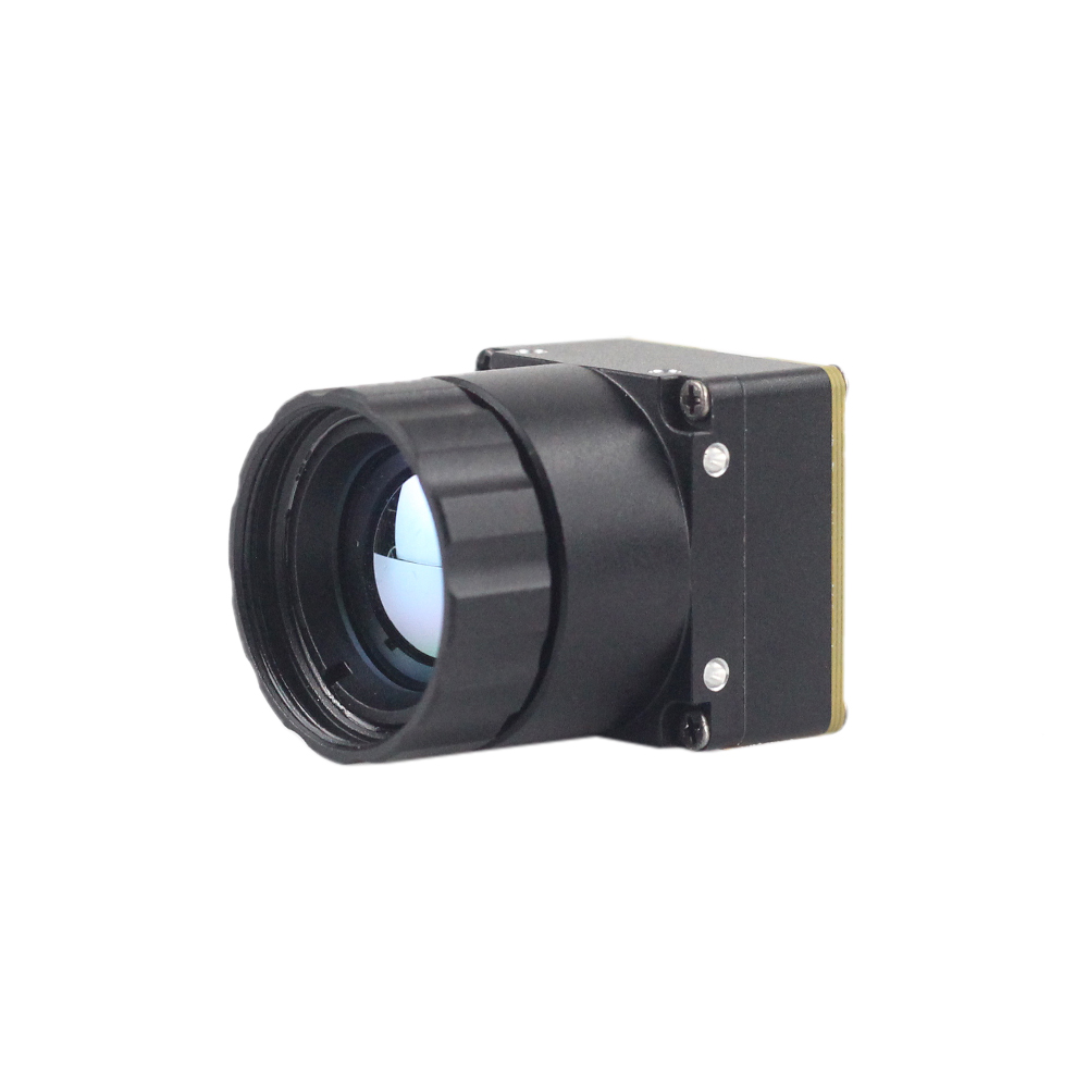
Uncooled LWIR USB Mini 640*512 Thermal Imaging Camera Core Module
Designed specifically for compact drone gimbals, advanced robotics, and handheld diagnostic platforms, this miniature uncooled infrared thermal imaging module delivers sharp and crisp image presentation, compact dimensions, and aggressive cost efficiency. Featuring an ultra-compact chassis footprint of just 21mm × 21mm, it is engineered for harsh, fluctuating operating environments.
| Native Resolution: | 640 × 512 (Optional 640 × 480 configurations) |
| Pixel Pitch & Spectral: | 12 µm VOx Microbolometer; 8 µm to 14 µm spectral band |
| Optical Focal Lengths: | 5mm, 9mm, 13mm, 18mm, 35mm, 50mm, 75mm, 100mm, 150mm options |
| Thermal Sensitivity: | < 40 mK (@ f/1.0, 300K, 25Hz/50Hz) |
| Dimensions & Ingest: | 21mm × 21mm bare body; USB 2.0 / USB-C / DVP / LVDS outputs |
Uncooled LWIR Mini 256*192 Thermal Imaging Camera Module
The Mini 256 Uncooled LWIR Thermal Camera Module incorporates high-performance infrared detectors for ultra-clear thermal imaging and precise temperature measurement. Delivering form factors similar to DJI enterprise cores, it captures infrared radiation and outputs a uniform thermal image with integrated radiometry, making it an exceptional payload for specialized aerial robotics such as subsurface landmine detection, pipe surveillance, and remote sensing.
| Native Resolution: | 256 × 192 pixels |
| Pixel Pitch: | 12 µm high-density uncooled VOx matrix |
| Thermal Radiometry: | High-uniformity calibrated radiometric stream with temperature readout |
| Thermal Sensitivity: | < 50 mK (@ f/1.0, 300K, 25Hz) |
| Target Application: | UAV landmine tracking, industrial predictive diagnostics, wearable systems |
6. Thermal Optics Selection & Detection Range Calculation
Optical engineering for long-wave infrared sensors differs fundamentally from visible-light camera design. Standard optical glasses (such as BK7, fused silica, and soda-lime glass) become opaque within the 8 µm to 14 µm spectral window. Microbolometer optics require specialized infrared-transmitting materials:
- ✅ Monocrystalline Germanium (Ge): The premier optical material for high-resolution LWIR cores. Germanium has a very high refractive index ($n \approx 4.0$), allowing optical engineers to design high-power lenses with minimal surface curvature. However, Germanium requires Diamond-Like Carbon (DLC) or Anti-Reflective (AR) coatings to eliminate surface reflection and is susceptible to thermal defocusing without active mechanical or optical athermalization.
- ✅ Chalcogenide Glass: Moldable synthetic infrared glasses (such as GASIR) that offer exceptional thermal stability over wide operational ranges. They can be pressed into aspheric profiles at lower production costs, making them ideal for budget-constrained embedded systems.
- ✅ Zinc Selenide (ZnSe): Offers wide multi-spectral transmission across visible and LWIR spectra, frequently used in laboratory equipment and alignment optics.
Thermal lens focal lengths directly determine the Field of View (FOV) and the theoretical operational range based on Johnson's Criteria. Under Johnson's Criteria, target resolution requirements are defined by critical dimension pixel thresholds across the target:
- ⚙️ Detection (1.5 pixels across critical dimension): An observer can distinguish that an object is present in the field of view.
- ⚙️ Recognition (6.0 pixels across critical dimension): An observer can determine the general class of the object (e.g., distinguishing a person from a vehicle).
- ⚙️ Identification (12.0 pixels across critical dimension): An observer can confirm specific target attributes (e.g., identifying a specific vehicle type or armed personnel).
The mathematical formula for calculating theoretical Detection, Recognition, and Identification (DRI) distance is:
Distance (meters) = [ Critical Dimension (m) × Focal Length (mm) ] / [ Target Dimension Pixels × Pixel Pitch (mm) ]
For example, calculate the theoretical detection range ($1.5\text{ pixels}$) of a standing human target ($H = 1.8\text{ meters}$) using the Mini 640 core ($12\text{ µm} = 0.012\text{ mm}$ pitch) across multiple optional lens configurations:
| Focal Length (mm) | Horizontal FOV (approx.) | Human Detection (1.5 px) | Human Recognition (6 px) | Vehicle Detection (2.3m, 1.5 px) |
|---|---|---|---|---|
| 9 mm | 48.8° | 900 meters | 225 meters | 1,150 meters |
| 18 mm | 24.6° | 1,800 meters | 450 meters | 2,300 meters |
| 35 mm | 12.5° | 3,500 meters | 875 meters | 4,472 meters |
| 75 mm | 5.9° | 7,500 meters | 1,875 meters | 9,583 meters |
When selecting optics, optical speed (f-number) directly impacts thermal sensitivity. Radiometric power incident on the FPA is inversely proportional to the square of the optical f-number:
\text{NETD}_{\text{system}} \propto (f/\#)^2
An f/1.0 lens assembly passes twice the infrared photonic flux of an f/1.4 lens. Selecting a higher f-number optic degrades system NETD from < 40 mK to approximately 80 mK, cutting your ability to resolve fine thermal details in half. Industrial integrators must ensure optical f-numbers match the calibration specifications of their core.
7. Industrial Applications: Unmanned Platforms, Machine Vision, and Security
Compact USB microbolometers bridge the gap between heavy, expensive legacy thermal systems and space-constrained modern edge devices. By combining direct USB interfaces with low power consumption, these sensor modules enable several high-impact applications:
1. Aerial Mine and UXO Detection Payloads
Buried metallic and non-metallic anti-personnel landmines introduce minute differences in thermal inertia compared to surrounding topsoil. During diurnal heating and cooling cycles, soil directly above buried ordnance changes temperature at a different rate than undisturbed earth. Drones equipped with the Mini 256*192 or Mini 640*512 modules can scan large fields from altitudes of 10 to 30 meters. Operating in radiometric Y16 mode, onboard edge processors detect these subtle, circular thermal differentials (< 0.1 °C thresholds) in real time, automatically marking GPS hazard waypoints on digital elevation models without exposing demining personnel to blast risks.
2. Utility-Scale Photovoltaic and High-Voltage Infrastructure Inspection
Solar farm inspections require identifying failing bypass diodes, localized cell cracks, and micro-hotspots across hundreds of thousands of panel surfaces. A drone payload integrating an uncooled USB thermal module can stream radiometric video into an onboard companion computer running edge inference models. The system flags localized heating anomalies exceeding normal panel operational limits ($+10\text{ K}$ to $+20\text{ K}$) and logs georeferenced thermal snapshots, speeding up inspections compared to manual ground surveys with handheld probes.
3. Factory Automation, Switchgear Cabinets, and Predictive Maintenance
Fixed robotic arms, Automated Guided Vehicles (AGVs), and industrial manufacturing cells face costly downtime when high-load motor bearings or high-voltage terminal junctions overheat. Permanent integration of a 21mm × 21mm USB thermal module inside high-voltage switchgear cabinets enables round-the-clock monitoring. Industrial controllers analyze raw 16-bit feeds continuously: if any electrical terminal block experiences a temperature spike due to mechanical loosening or harmonic distortion, the system triggers an emergency shutdown sequence well before catastrophic fire or arc-flash events occur.
8. Deep-Dive Engineering FAQ
Can I stream radiometric thermal data in real-time to a Raspberry Pi or Linux SBC?
At the system level, the module exposes two video endpoints or an interleaved Y16 payload under the standard Linux Video4Linux2 (V4L2) driver framework. Rather than restricting engineers to low-level proprietary APIs, our modules allow the raw sensor data stream to be opened directly via /dev/video* nodes using native Linux system calls, raw file descriptors, or OpenCV pipelines (cv::VideoCapture).
Each 16-bit pixel encodes temperature data with a resolution of 0.01 K or direct uncompressed analog counts. Our C++ and Python SDKs abstract the calibration routines, coordinate conversion, and optical non-uniformity correction lookups, allowing edge processors like the Raspberry Pi 4/5, NVIDIA Jetson, or Rockchip platforms to perform real-time pixel extraction, temperature bounding, and downstream visual serving at full frame rates (25Hz/50Hz) with minimal CPU overhead.
How do I handle USB-C OTG power injection when running long-duration thermal monitoring on embedded hosts?
In continuous industrial monitoring installations, single-board computers configured in OTG (On-The-Go) host/peripheral modes often suffer from brownouts, thermal throttling, or bus drops if the internal 5V rail dips under peak sensor and processing loads. Our camera modules mitigate this through an optimized, low-power uncooled microbolometer architecture that consumes less than 1.2W under maximum processing load.
For continuous deployments, we recommend isolating power delivery using a USB-C breakout board or a dual-channel Y-cable harness. In this configuration, the high-speed differential data lines (D+/D- or high-speed TX/RX pairs) terminate directly at the host processor, while the VBUS and Ground lines link to an external, regulated 5V (1.5A+) power supply. This prevents host supply noise from coupling into the sensitive analog-to-digital read-out circuitry (ROIC), helping maintain low noise performance (<40mK NETD) across long operational runs.
Why should I upgrade to an uncooled microbolometer module instead of DIY thermopile arrays like the MLX90640?
Low-cost thermopile arrays rely on microscopic thermocouple junctions that detect bulk temperature differentials. Due to their mechanical structure, thermopiles generate significant thermal drift, lack precise spatial resolution, and yield high noise floors (NETD typically hovering between 100mK and 150mK), with refresh rates slowing down drastically when reading accurate signals (often below 8Hz).
In contrast, our uncooled LWIR cores use precision Vanadium Oxide (VOx) microbolometer FPAs with fine 12µm pixel pitches. Moving from a 32×24 array (768 pixels) to a 640×512 array (327,680 pixels) provides a 426-fold increase in spatial data. This extra resolution is essential for identifying small thermal targets, performing quantitative PCB-level diagnostics, inspecting mechanical assemblies, and running edge AI models like YOLO or TensorRT engines that fail on the low-resolution, blurred output of thermopile sensors.
📚 References & Further Reading
- Industry Standard Single-Board Computing: Explore reference carrier schematics and embedded hardware on the official Raspberry Pi Foundation platform.
- Embedded Carrier Boards & Hardware: Find modular baseboards, interface hats, and edge AI compute kits via Waveshare.
- Related Integration Guide: Learn how to initialize embedded thermal drivers with our step-by-step RS300 V4L2 kernel driver guide for Raspberry Pi.
- Optical Selection Framework: Read our technical guide on how to choose an infrared thermal camera core for harsh industrial environments.
- Product Range: View our complete portfolio of high-resolution sensors in the Thermal-Image module catalog.