Best Thermal Imager Guide: Budget Gadgets vs. Industrial AI LWIR Modules
2026年10月19日
Thermal Cameras Explained: How They Work, Core Tech, and What's Actually Worth Buying
2026年10月20日
Thermal Imaging Cameras Guide: Resolution, Edge AI & Industrial Specs Unlocked
In modern industrial automation, predictive maintenance, critical infrastructure monitoring, and autonomous airborne inspection, thermal imaging cameras have transitioned from basic troubleshooting gadgets into mission-critical quantitative instruments. Historically restricted to coarse qualitative heat-leak surveys using bulky handheld units, contemporary long-wave infrared (LWIR) devices now operate as autonomous, edge-computing radiometric nodes. By gathering emitted electromagnetic radiation across the 8 to 14 micrometer (μm) spectrum and converting incoming photon flux into traceable thermodynamic values, these sensors empower engineers to audit dynamic mechanical friction, catch electrical micro-arcing before fire outbreaks occur, map localized photovoltaic cell degradation, and monitor perimeters through complete darkness, thick dust, or heavy atmospheric obscurants.
However, deploying an industrial-grade thermal subsystem means filtering past superficial marketing metrics. Specifying an uncooled LWIR core requires a disciplined evaluation of interdependent technical factors: microbolometer material chemistry (Vanadium Oxide vs. Amorphous Silicon), Noise Equivalent Temperature Difference (NETD), Instantaneous Field of View (IFOV), pixel pitch geometries, thermal time constants, and transport bus latencies. As manufacturing facilities accelerate toward Industry 4.0 automation, raw focal plane arrays coupled with on-chip Edge AI pipelines are systematically replacing closed, slow-refresh handheld imagers.
Table of Contents
- 👉 1. LWIR Sensor Physics & Microbolometer Architecture
- 👉 2. Resolution Paradigms, IFOV & Infrared Optics
- 👉 3. Radiometric Precision, NUC & Calibration Mechanics
- 👉 4. Edge AI Micro-Architectures & Autonomous Inference
- 👉 5. Embedded System Integration & Communication Protocols
- 👉 6. OEM Industrial Thermal Hardware: Core Comparison Matrix
- 👉 7. Deep-Dive Industrial Thermal FAQ
1. LWIR Sensor Physics & Microbolometer Architecture
Uncooled thermal imaging cameras operate under the foundational principles of Planck’s Law and the Stefan-Boltzmann Law. Every object with a temperature above absolute zero (0 Kelvin) continuously emits electromagnetic radiation with an emissive power proportional to the fourth power of its thermodynamic temperature ($E = \varepsilon \sigma T^4$). For typical terrestrial and industrial targets spanning -40°C to +500°C, this spectral radiance peaks cleanly inside the Long-Wave Infrared (LWIR) atmospheric transmission window between 8 μm and 14 μm. Capturing this photon flux without bulky, power-hungry cryogenic Stirling coolers relies on specialized micro-electro-mechanical system (MEMS) focal plane arrays (FPAs).
The core sensor element is the microbolometer. Unlike photon-counting detectors found in cooled military systems, a microbolometer is a thermal detector. It absorbs incident infrared energy and converts that absorbed power into a measurable change in electrical resistance. Each pixel cell features an ultra-thin absorbing membrane suspended above a silicon readout integrated circuit (ROIC) by tiny micro-machined anchor arms. These arms serve two conflicting masters: they must conduct electrical signals to the ROIC while maintaining near-perfect thermal isolation to prevent heat from leaking into the underlying silicon substrate before it can be measured.
When long-wave infrared radiation hits this floating bridge, the active thin film warms up. The thermal time constant ($\tau$), governed by the ratio of heat capacity ($C$) to thermal conductance ($G$) through the suspension legs ($\tau = C / G$), determines how quickly the pixel heats and cools. In high-speed industrial lines or flight stabilization systems, this parameter is critical. If the time constant exceeds 12 milliseconds, rapid movements generate motion smear, compromising temperature accuracy across dynamic targets.
The ROIC interrogates this resistance shift during a brief pulse integration window. By driving an ultra-stable current or voltage bias across the bridge, the ROIC routes tiny millivolt variations through integrated low-noise amplifiers, multiplexers, and high-precision analog-to-digital converters (ADCs), outputting raw 14-bit or 16-bit digital values for real-time processing.
THERMAL IMAGING REAL-TIME VIDEO
System architects must choose between two primary thin-film semiconductor compositions when specifying focal plane arrays:
- ⚙️ Vanadium Oxide (VOx): Widely recognized as the industrial gold standard for mission-critical thermography. VOx boasts a remarkably high negative Temperature Coefficient of Resistance (TCR), typically ranging from -2% to -3% per Kelvin at room temperature. More importantly, its crystalline lattice exhibits minimal 1/f low-frequency electronic flicker noise. Because VOx produces an exceptional signal-to-noise ratio (SNR), microbolometer membranes can be manufactured with minimal mass, yielding snappy thermal time constants between 8 and 12 milliseconds. This allows clean 30 Hz to 60 Hz frame rates free of ghosting, while preserving high structural stability against thermal aging over years of continuous plant operation.
- ⚙️ Amorphous Silicon (α-Si): A popular alternative engineered for cost-sensitive commercial devices. Amorphous Silicon can be deposited using standard, high-volume silicon CMOS fabrication lines, which lowers initial production costs and improves manufacturing yields. However, α-Si features an inherently disordered atomic structure. This non-crystalline matrix creates higher 1/f noise floors and delivers a lower TCR, typically hovering between -1.5% and -2.0% per Kelvin. To capture a workable signal, α-Si sensors often require larger pixel volumes, driving thermal time constants up toward 14 to 20 milliseconds. In dynamic industrial applications, systems using α-Si rely on aggressive spatio-temporal noise filtering algorithms that can soften sharp edges and wash out subtle thermal gradients.
The critical benchmark for thermal sensor sensitivity is Noise Equivalent Temperature Difference (NETD), expressed in millikelvins (mK). NETD represents the temperature differential that yields a signal-to-noise ratio of unity across the detector array—in simple terms, the point where the thermal signal disappears into the sensor's own electronic noise floor. The lower the NETD rating, the smaller the thermal gradient the camera can resolve.
- ✅ Grade A Industrial (NETD < 30mK to 40mK): Standard for precision predictive maintenance, circuit board diagnostics, and aerospace non-destructive testing (NDT). Captures micro-thermal anomalies such as mechanical stress concentrations, composite delamination, or faint subsurface moisture penetration.
- ✅ Grade B Mid-Tier (NETD 40mK to 60mK): Well-suited for standard factory security monitoring, fluid tank level auditing, and commercial UAV asset surveys under moderate ambient thermal contrast.
- ⚙️ Commercial Consumer Grade (NETD > 70mK to 100mK): Found in entry-level handheld tools and budget smartphone attachments. These sensors struggle in low-contrast conditions, delivering noisy, salt-and-pepper images that obscure fine anomalies.
Deploying sensitive microbolometers in harsh industrial environments requires robust physical and electrical protection. Heavy machinery, variable-frequency drives (VFDs), and large electric motors dump substantial electromagnetic interference (EMI) onto data lines. To prevent data corruption, industrial designs incorporate military-grade connectors, sealed enclosures, and high-integrity cabling from suppliers such as TE Connectivity, keeping serialized high-speed output lines clean between the microbolometer ROIC and downstream processors.
2. Resolution Paradigms, IFOV & Infrared Optics
Engineers moving from visible-light machine vision to thermography often face a shock regarding resolution. While visible CMOS sensors routinely pack 4K or 20-megapixel counts into affordable formats, uncooled LWIR thermal arrays typically max out between 384×288 and 1280×1024 pixels. This difference is driven by pure physics: visible light occupies wavelengths between 0.4 μm and 0.7 μm, whereas long-wave infrared spans 8 μm to 14 μm—an order of magnitude larger. According to the Abbe diffraction limit, shrinking microbolometer pixel pitches much below 10 μm causes severe diffraction blurring, optical crosstalk, and diminished photon collection per cell.
- ✅ Sub-Arrays (160×120 to 256×192): Up to 49,152 radiometric pixels. Ideal for basic spatial awareness, HVAC line checks, and simple proximity detection. Quantitative industrial troubleshooting at safe working distances is limited.
- ✅ Workhorse Commercial Arrays (384×288): Yielding 110,592 discrete measurement points. Considered the optimal balance of SWaP (Size, Weight, and Power) for drone gimbals, robotic inspections, and predictive machinery audits. System developers can review optical mounts, focal matching, and UAV payload considerations in this comprehensive 384x288 UAV sensor integration analysis.
- ✅ High-Definition Core Arrays (640×512): Delivering 327,680 individual radiometric pixels. This resolution serves as the baseline for mission-critical automation, factory machine vision, search-and-rescue payloads, and automated electrical switchgear monitoring.
- ✅ Ultra-High Infrastructure Arrays (1280×1024): Offering over 1.31 million true radiometric pixels. Multiplies spatial density fourfold over 640×512 arrays. It enables operators to monitor massive substation yards, long pipeline corridors, or long-range perimeters with wide field-of-view lenses without losing single-component detail.
Evaluating an optical setup requires calculating the Instantaneous Field of View (IFOV). IFOV dictates the physical angle subtended by a single pixel, establishing the system's theoretical spatial resolution limit:
IFOV (milliradians) = [ Pixel Pitch (μm) / Optical Focal Length (mm) ]
For example, a sensor with a 12 μm pixel pitch paired with a 25 mm focal length lens produces an IFOV of 0.48 mrad. At an inspection standoff distance of 10 meters, each individual pixel covers a physical square measuring 4.8 mm by 4.8 mm.
However, relying solely on IFOV for accurate temperature measurement is a dangerous mistake. Due to optical diffraction, lens aberrations, and charge diffusion in the sensor substrate, a single illuminated pixel cannot collect 100% of the incoming thermal energy from a point source. Engineers must calculate using the Measurement Instantaneous Field of View (MFOV), often called the Spot Size Ratio (SSR):
- ⚙️ 1-Pixel Rule (Detection): An anomaly covering a single pixel might trigger a color shift in the display, but its reported temperature will be heavily contaminated by background radiation.
- ⚙️ 3×3 Pixel Matrix (Standard MFOV): An anomaly must span at least a 3×3 pixel block to register an approximate temperature reading (capturing roughly 90% of true radiant flux).
- ⚙️ 4×4 Pixel Matrix (High-Accuracy Metrology): For critical industrial inspections and contract audits, target features should span at least a 4×4 contiguous pixel array to ensure complete energy collection, independent of optical edge effects.
Focusing these long-wave infrared rays requires non-traditional optical substrates. Standard silicate glass is completely opaque across the 8 μm to 14 μm band, absorbing thermal photons within the first few microns of glass. Industrial thermal lenses are therefore diamond-turned from exotic optical materials:
- ⚙️ Single-Crystal Germanium (Ge): The dominant high-performance thermal optic material. Germanium features a high refractive index of roughly 4.0, which allows lens designers to produce fast, low f-number assemblies (f/1.0 to f/1.2) while controlling spherical and chromatic aberrations. However, bare Germanium reflects roughly 47% of incident light at each air-to-glass interface. High-efficiency Anti-Reflective (AR) or Diamond-Like Carbon (DLC) hard coatings are mandatory to push transmission efficiency above 95% while resisting sand, acid rain, and washdown solvents.
- ⚙️ Chalcogenide Glass Compounds: Advanced amorphous vitreous materials consisting of sulfur, selenium, and tellurium. Chalcogenide glass softens at lower temperatures, making it suitable for precision glass molding. This enables cost-effective high-volume production of complex aspheric lens designs, making it popular for automotive sensors and budget UAV modules.
3. Radiometric Precision, NUC & Calibration Mechanics
A crucial technical boundary separates qualitative imaging devices from fully radiometric instruments. A qualitative camera produces false-color video to show relative temperature differences across a scene. In contrast, a fully radiometric camera operates as an array of calibrated pyrometers: every discrete coordinate in the frame corresponds to an absolute, traceable thermodynamic temperature value. Converting raw digital counts from the ROIC into accurate Kelvin or Celsius readings requires real-time compensation for several environmental variables:
- ⚙️ Target Emissivity (ε): Emissivity is the efficiency with which a surface emits infrared radiation compared to an ideal blackbody radiator at identical temperatures. Organic materials, carbon steel, and matte paint display high emissivities between 0.90 and 0.98, yielding stable, accurate temperature measurements. In contrast, unoxidized, polished metals—such as copper busbars, machined aluminum plates, and new stainless steel pipes—drop below 0.15. These surfaces behave like infrared mirrors, reflecting surrounding thermal energy rather than radiating their own. Without manual or per-pixel software corrections, an operator may measure a false reading, mistaking ambient room reflections for equipment temperatures.
- ⚙️ Reflected Apparent Temperature ($T_{refl}$): To offset radiation reflected off low-emissivity targets, radiometric software algorithms must account for ambient background heat. In tight electrical switchgear cabinets, internal ambient heat sources must be mapped and mathematically subtracted from the total energy reaching the focal plane array.
- ⚙️ Atmospheric Transmittance & Path Attenuation: While the LWIR spectrum cuts through clean air with minimal attenuation, airborne humidity, particulate smog, and long distance paths absorb and re-emit long-wave infrared energy. Industrial radiometric processors must calculate path transmission corrections based on ambient relative humidity and absolute distance values to preserve measurement accuracy within ±2°C or ±2% of full-scale readings.
Because microbolometer arrays lack active cryogenic cooling, their internal sensor temperature shifts with changes in camera housing temperature, processor heat, and ambient conditions. This thermal drift causes spatial variations across the detector matrix, introducing fixed-pattern noise (FPN) that can obscure real targets. To maintain calibration accuracy, thermal cameras rely on Non-Uniformity Correction (NUC):
- ⚙️ Mechanical Shutter NUC: At regular intervals or when internal thermistors detect an internal temperature drift (typically Δ0.5°C), a small internal solenoid sweeps a high-emissivity, uniform shutter blade in front of the array for 150 to 300 milliseconds. The processor reads this uniform reference field and calculates a baseline offset correction matrix for every single pixel. This eliminates fixed-pattern noise, resets drift, and maintains absolute radiometric calibration.
- ⚙️ Shutterless Algorithmic NUC: On dynamic platforms—such as autonomous aerial vehicles, anti-aircraft targeting suites, and automated guided vehicles (AGVs)—a sudden 300-millisecond video freeze can disrupt target tracking or navigation. Shutterless NUC systems use machine-vision algorithms to monitor continuous inter-frame scene motion, calculating and updating pixel gain and offset corrections without mechanical occlusion.
Modern industrial cores also utilize dual-gain radiometric readouts:
- ✅ High-Gain Mode: Compresses the overall measurement scale (e.g., -20°C to +150°C) to maximize thermal sensitivity (NETD < 35mK). Ideal for finding delicate thermal faults on microelectronics or building envelope insulation leaks.
- ✅ Low-Gain Mode: Expands the dynamic range (e.g., 0°C to +650°C, or up to +1500°C with specialized internal filters). This prevents pixel saturation during heavy industrial processes like metal casting, glass manufacturing, or fire rescue.
4. Edge AI Micro-Architectures & Autonomous Inference
Industrial thermal inspection has outgrown manual monitoring. Historically, field technicians had to watch banks of monochrome or ironbow monitors, manually adjusting palette spans and visually hunting for hot spots. This manual model fails in high-speed, continuous factory environments and large autonomous aerial inspection sweeps. Modern architectures push intelligence directly to the sensor level, pairing uncooled microbolometer cores with low-power Neural Processing Units (NPUs) and onboard digital signal processors (DSPs).
Crucially, edge AI inference operates directly on the raw, linear 14-bit or 16-bit radiometric output streaming off the ROIC. Standard downstream compression pipelines convert thermal signals into lossy 8-bit YUV or RGB streams to drive visual displays, stripping out nuanced radiometric depth. By feeding the raw digital output straight into quantized neural networks, edge models analyze subtle mathematical variations that never appear on a visual monitor.
- ✅ Degraded Visual Environments (DVE) Autonomous Tracking: Standard optical cameras fail in smoke, dense dust, steam, or absolute darkness. Quantized convolutional networks (such as YOLOv8-Thermal, MobileNet-SSD, or lightweight Vision Transformers) running directly on the sensor platform detect, classify, and track human personnel, vehicles, structural hazards, and industrial assets using pure thermal signatures.
- ✅ Dynamic Rate-of-Rise (ΔT/Δt) Diagnostics: Simple threshold systems wait until a component reaches a pre-set failure temperature (e.g., 95°C) to sound an alarm. By that point, bearing destruction, transformer insulation failure, or wire insulation melting is often already underway. Edge AI models continuously track the rate of thermal change (ΔT/Δt) over time, factoring in ambient factory temperatures and motor RPM data. This enables the system to flag dry bearings or phase unbalances hours before critical temperature limits are reached.
- ✅ Autonomous Optical Gas Imaging (OGI): By pairing narrow bandpass optical filters (e.g., 10.5 μm for sulfur hexafluoride or 7.7 μm for volatile hydrocarbons) with high-sensitivity VOx sensors, cameras can capture the absorption signatures of escaping gases. Onboard convolutional networks analyze plume shapes, trace movement vectors against shifting background temperatures, and automatically issue spatial leak alerts without requiring continuous human oversight.
To prototype and deploy these embedded machine learning models, systems engineers routinely mate core thermal modules with compact carrier boards, specialized microcontrollers, and edge computing platforms provided by ecosystems such as Waveshare. These computing boards provide the GPIO pinouts, MIPI CSI-2 routes, and high-speed communication buses required to build self-contained, intelligent edge sensing nodes.
5. Embedded System Integration & Communication Protocols
When selecting thermal imaging cameras for integration into space-constrained UAV payloads, robotic submersibles, automated production machinery, or tactical gear, engineers must balance the core pillars of SWaP-C: Size, Weight, Power, and Cost. Choosing the right hardware interface and communication protocol directly impacts system efficiency, design complexity, and data integrity:
- ⚙️ USB-C & Standardized UVC Pipelines: The USB Video Class (UVC) protocol has simplified rapid prototyping and desktop edge computing. Modern USB-C thermal modules provide broad plug-and-play cross-compatibility across Linux, Windows, ROS (Robot Operating System), and Android platforms without requiring custom low-level kernel drivers. Advanced industrial USB modules leverage dual-stream endpoints: one endpoint outputs standard 8-bit YUV/H.264 video for real-time monitoring, while an interleaved secondary channel feeds raw 14-bit radiometric matrices to backend analytics software.
- ⚙️ MIPI CSI-2 Embedded Interconnect: The preferred interface for ultra-compact, low-latency mobile platforms. MIPI CSI-2 routes raw, uncompressed thermal pixel streams directly into the internal Image Signal Processor (ISP) of host processors like the NVIDIA Jetson, Rockchip RK3588, or Raspberry Pi Compute Modules. By cutting out intermediate USB bridge controllers and protocol conversions, MIPI cuts system latency down to single-digit milliseconds, minimizes CPU overhead, and reduces PCB real estate. Engineers looking for wiring pinouts, clock routing guidelines, and trace impedance targets can refer to this technical guide to uncooled MIPI thermal camera modules.
- ⚙️ Network RTSP & Industrial ONVIF: Permanent installation throughout substations, factory floors, and security zones relies on network-connected thermal IP cameras. These devices encode video internally into H.264/H.265 streams delivered via Real-Time Streaming Protocol (RTSP) over copper Ethernet or optical fiber. Diagnostic metadata and localized threshold alarms route over ONVIF Profile S/T extensions or industrial Modbus/TCP registers, interfacing cleanly with plant-wide supervisory control and data acquisition (SCADA) networks.
- ⚙️ Legacy Analog CVBS: In analog FPV tracking platforms, specialized tactical headsets, and low-latency aerial gimbals, digital encoding latency can introduce unacceptable flight delays. Native analog CVBS (Composite Video Blanking and Sync) output delivers a zero-latency, analog video feed routed over simple coaxial cabling straight to pilot displays or video transmitters.
For an overarching engineering guide detailing how to balance optical focal lengths, casing environmental tolerances, power isolation circuits, and hardware protocol options, engineers can review this comprehensive detailed infrared thermal camera module selection roadmap.
6. OEM Industrial Thermal Hardware: Core Comparison Matrix
System architects often need to balance compact, lightweight cores designed for aerial payloads against heavy-duty, high-resolution optical engines designed for wide-area infrastructure monitoring. Below, we compare two production-ready uncooled LWIR solutions built for demanding field conditions.
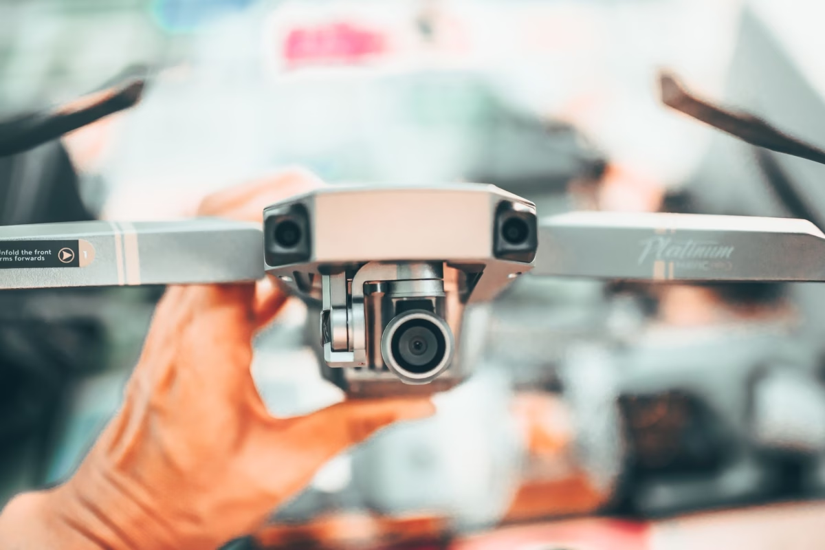
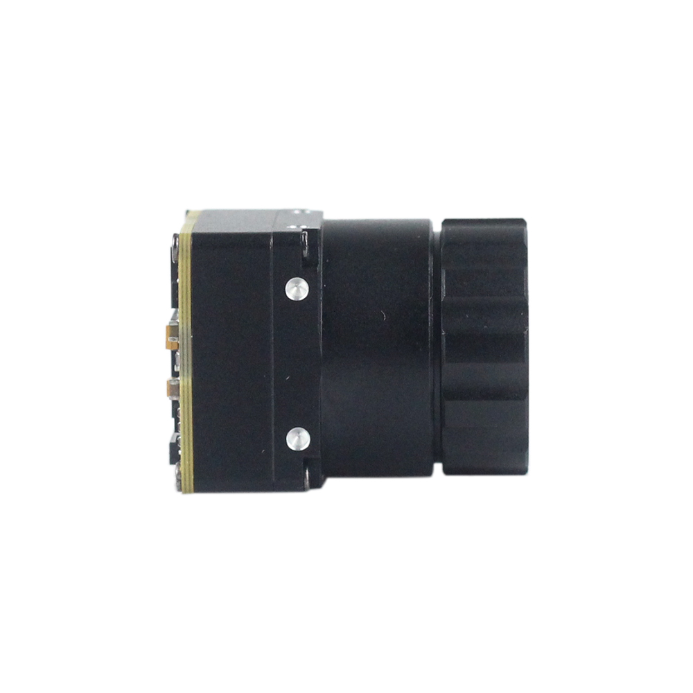
Uncooled LWIR USB Mini 640*512 Thermal Imaging Camera Core Module For Drones Similar To DJI

Form Factor & Profile: Ultra-compact mini-size measuring an exceptionally small 21mm × 21mm footprint. Engineered specifically for weight-sensitive gimbals, robotic systems, and aerial integrations matching and exceeding DJI enterprise-class requirements.
Core Sensor Resolution: Delivers sharp and crisp native 640×512 resolution (with optional 640×480 resolution mode) on an uncooled LWIR microbolometer platform.
Optics Ecosystem: Features extensive optical adaptability with interchangeable athermalized lenses spanning 5mm, 9mm, 13mm, 18mm, 35mm, 50mm, 75mm, 100mm, and 150mm options.
Performance & Cost: Delivers stable performance, low cost, and strong environmental adaptability for deployment across severe industrial and aerospace environments.
High Resolution Uncooled Infrared 1280*1024 Thermal Imaging LWIR Camera
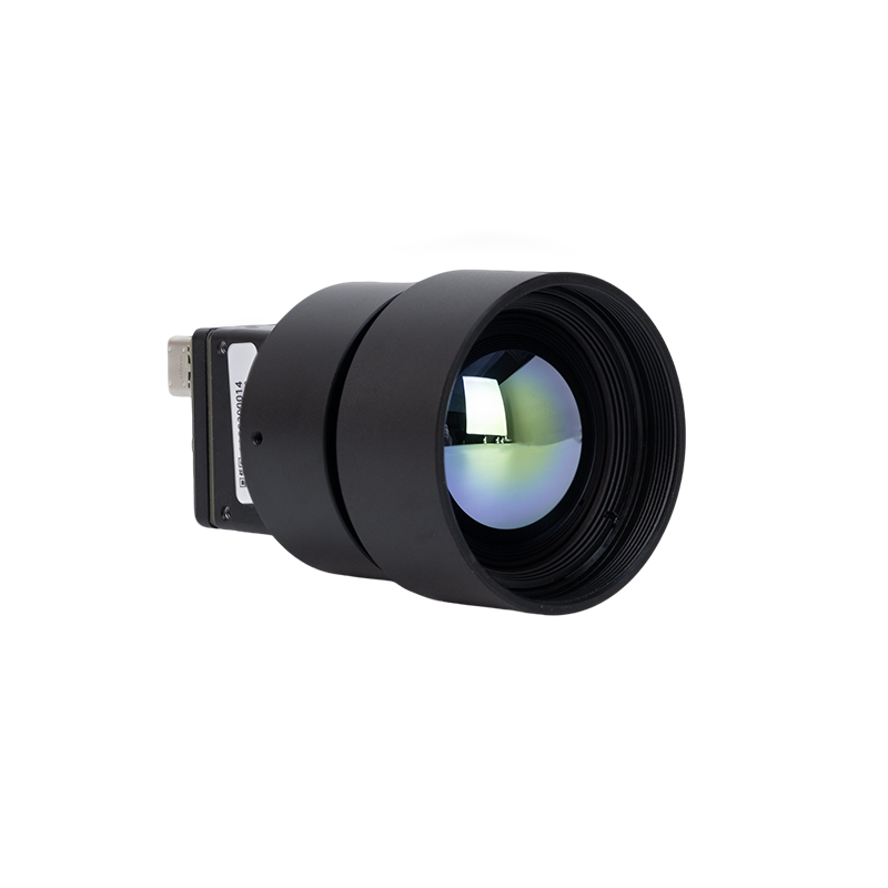
Sensor Architecture: Professional wholesale high-resolution 1280×1024 uncooled infrared thermal imaging LWIR camera matrix yielding over 1.31 million true radiometric sensing pixels.
Integrated Optics: Equipped with a precision-engineered 25mm Germanium lens assembly optimized for high photon throughput, maximum MTF performance, and low optical aberration across the LWIR spectrum.
Deployment Regimes: Built for wide-area continuous infrastructure monitoring, automated factory process inspection, predictive substations diagnostics, and long-range border and perimeter tracking.
Data Processing: Outputs high-bit-depth thermal imagery with rich pixel counts that allow edge neural networks to classify distant targets without pixelation artifacts.
| Model / Feature | Array Resolution | Lens Options | Physical Dimensions | Key Value Propositions | Primary Target Uses |
|---|---|---|---|---|---|
| Mini 640 LWIR Core | 640×512 native (640×480 optional) | 5 / 9 / 13 / 18 / 35 / 50 / 75 / 100 / 150mm | 21mm × 21mm (Mini-Size) | Sharp image presentation, compact SWaP profile, low cost, strong environmental adaptability. | Commercial UAV gimbals (DJI-class alternatives), mobile robotics, field IoT devices. |
| 1280 High-Res Camera | 1280×1024 (HD Matrix) | 25mm High-Throughput Lens | Heavy-duty industrial enclosure | Over 1.31M pixels, exceptional spatial detail, long-range detection, high MTF fidelity. | Perimeter surveillance, substation monitoring, machine vision inspection, border security. |
7. Deep-Dive Industrial Thermal FAQ
Are sub-$400 budget thermal cameras actually worth buying, or are they just toys?
What is the benefit of integrating an uncooled thermal camera core over buying an off-the-shelf handheld?
How does Edge AI improve thermal imaging cameras in field applications?
📚 References & Further Reading
- Industry Standard: Industrial interconnects and ruggedized signal integrity architectures via TE Connectivity
- Industry Standard: Microcomputing, carrier boards, and embedded hardware interfaces via Waveshare
- Related Guide: Moduł kamery termowizyjnej 384x288: sensor sweet spot dla dronów
- Related Guide: Руководство по выбору инфракрасных тепловизионных модулей
- Related Guide: Niechłodzony moduł kamery termowizyjnej na podczerwień MIPI 640 / 384 / 256