Thermal Imaging Cameras Guide: Resolution, Edge AI & Industrial Specs Unlocked
2026年10月20日
Infrared Thermal Camera Guide: Sensor Tech, Real Resolution & Industrial Buying Tips
2026年10月21日

Thermal Cameras Explained: How They Work, Core Tech, and What's Actually Worth Buying
In automated process control, critical infrastructure monitoring, and unmanned aerial system (UAS) development, standard visible-spectrum optical sensors fail the moment environmental conditions deteriorate. Darkness, dense smoke, atmospheric obscurants, and complex background clutter blind conventional image sensors. Thermal imaging circumvents these limitations entirely by bypassing visible photon reflection and directly mapping emitted Long-Wave Infrared (LWIR) flux. However, specifying thermal cameras for mission-critical industrial use requires far more than matching headline resolution numbers; it demands an uncompromising analysis of detector physics, sensor material science, optical transmission limits, and radiometric calibration accuracy.
For hardware engineers, procurement specialists, and systems integrators, selecting the wrong thermal imaging core introduces severe liabilities: false-positive fire alerts, inaccurate thermal gradient mapping across printed circuit boards, and unrecoverable sensor drift under unstable ambient operating temperatures. This engineering blueprint deconstructs modern thermal imaging architectures from focal plane arrays (FPAs) to digital signal processing engines. We analyze the underlying radiometric physics, benchmark high-performance industrial cores, evaluate embedded deployment interfaces, and provide an objective procurement matrix designed to eliminate low-performing consumer gimmicks from your hardware stack.
Table of Contents
- 👉 1. Physics of Thermal Radiometry: How Thermal Cameras Actually Function
- 👉 2. Decoding Key Engineering Specs: What Separates Real Tools from Toys
- 👉 3. Industrial & Embedded Product Benchmark: Enterprise LWIR Modules
- 👉 4. Edge AI, Embedded Protocols, and Drone/Robotic Payloads
- 👉 5. What Is Actually Worth Buying? Selection Matrix for OEMs & Engineers
- 👉 6. Deep-Dive Technical FAQ
- 👉 7. Strategic Takeaway & Integration Roadmap
1. Physics of Thermal Radiometry: How Thermal Cameras Actually Function
Thermal cameras operate on the principle of blackbody radiation. Every physical object possessing a thermodynamic temperature above absolute zero (0 Kelvin or -273.15°C) naturally radiates electromagnetic energy generated by the random vibrational and rotational movements of its constituent atoms and charged molecules. Unlike standard visible spectrum imaging sensors that depend on an external ambient source of visible photons reflecting off an object's surface into an optical aperture, infrared sensors capture photons actively emitted by the body itself due to its thermal excitation state.
The baseline mathematical formulation governing this radiative mechanism is defined by Planck’s Radiation Law, which establishes the spectral radiance emitted per unit surface area, per unit solid angle, and per unit wavelength interval as a function of absolute temperature:
B(λ, T) = (2 * h * c²) / (λ&sup5; * [exp((h * c) / (λ * k_B * T)) - 1])
In this equation, h represents Planck’s constant (6.62607015 × 10⁻³⁴ J·s), c designates the speed of light within a vacuum (2.99792458 × 10&sup8; m/s), k_B denotes the Boltzmann constant (1.380649 × 10⁻²³ J/K), λ specifies the emission wavelength in meters, and T quantifies the absolute thermodynamic temperature in Kelvin. Integrating Planck’s spectral distribution across all electromagnetic wavelengths yields the fundamental Stefan-Boltzmann Law:
j* = ε * σ * T&sup4;
Here, the total hemispherical radiant emittance (j*) scales strictly in proportion to the fourth power of the absolute thermodynamic temperature, directly modulated by the target surface emissivity factor (ε) and the universal Stefan-Boltzmann constant (σ ≈ 5.670374 × 10⁻⁸ W·m−2·K−4). Furthermore, by differentiating Planck's function with respect to wavelength and solving for the point of zero slope, we arrive at Wien’s Displacement Law:
λ_max = b / T
Where Wien’s displacement constant b is approximately 2897.77 μm·K. For typical terrestrial and industrial targets operating within ambient environmental thermal regimes ranging from -20°C up to +100°C (253.15 K to 373.15 K), the peak electromagnetic photon flux concentrates decisively between 7.7 μm and 11.4 μm. This physical reality dictates why thermal cameras deployed for general automation, security, and robotic inspection converge on the 8 to 14 micrometer waveband.
1.1 Atmospheric Transmission Windows: SWIR, MWIR, and LWIR
The Earth's atmosphere is rich in gaseous molecules, predominantly water vapor, carbon dioxide, nitrous oxide, and ozone, which aggressively absorb and scatter infrared photons via vibrational-rotational molecular absorption bands. Consequently, terrestrial optical thermal sensing can only be conducted through narrow atmospheric "transmission windows" where molecular absorption attenuation reaches local minima:
- ⚙️ Short-Wave Infrared (SWIR, 1.0 to 3.0 μm): SWIR imaging behaves optically more like visible light than thermal radiation. It relies heavily on ambient solar, lunar, or artificial reflected photon flux rather than passive target self-emission. Because SWIR photons easily penetrate thin atmospheric haze, airborne moisture particles, and tinted architectural glass, it is widely utilized in specialized industrial sorting, agricultural moisture monitoring, and advanced surveillance. SWIR detectors require exotic Indium Gallium Arsenide (InGaAs) photodiode structures.
- ⚙️ Mid-Wave Infrared (MWIR, 3.0 to 5.0 μm): MWIR exhibits high sensitivity for high-temperature thermal signatures, combustion gas exhaust analysis, chemical plume tracking, and extreme long-range military tracking. However, because terrestrial objects at nominal room temperature emit minimal radiant flux in this band, MWIR focal plane arrays require cryocooled quantum photodetectors (such as Indium Antimonide, InSb, or Mercury Cadmium Telluride, MCT) operating at liquid nitrogen temperatures (~77 K). The required closed-cycle Stirling mechanical cryocoolers introduce heavy size, weight, power, and periodic maintenance burdens that limit continuous industrial automation deployment.
- ⚙️ Long-Wave Infrared (LWIR, 8.0 to 14.0 μm): LWIR represents the premier spectral regime for general-purpose predictive maintenance, continuous facility condition monitoring, tactical drone reconnaissance, structural diagnostic inspection, and perimeter thermal sensing. Because ambient scene energy peaks natively within this waveband, solid-state uncooled thermal sensors can operate without cryocoolers. This enables rugged, highly durable, low-SWaP (Size, Weight, and Power) sensor engines that run continuously for tens of thousands of hours without mechanical maintenance.
1.2 Focal Plane Array Physics: Microbolometer Materials (VOx vs. a-Si)
At the architectural core of modern uncooled LWIR thermal cameras resides a Focal Plane Array (FPA) consisting of a dense, micro-machined matrix of thermal detection elements known as microbolometers. Unlike visible CMOS sensors that convert incident photons directly into electronic charge carriers via the internal photoelectric effect, a microbolometer pixel operates as a micro-scale thermal energy reservoir. Each individual pixel consists of a thin infrared-absorbing membrane elevated approximately 2 micrometers above an underlying silicon Complementary Metal-Oxide-Semiconductor (CMOS) Readout Integrated Circuit (ROIC). This membrane is suspended on microscopic, high-aspect-ratio lithographic support legs designed to maximize thermal resistance and minimize parasitic conductive heat loss to the silicon substrate.
When incoming 8 to 14 μm infrared radiation hits the absorbing layer, the absorbed radiant flux raises the temperature of the suspended membrane by fractions of a milliKelvin. This temperature shift induces a measurable change in the electrical resistance of the underlying thermistor material. The underlying ROIC periodically interrogates each pixel by applying a calibrated bias voltage, measuring the resulting current flow, amplifying the signal, and converting it via integrated analog-to-digital converters (ADCs) into a stream of raw digital counts proportional to the incident radiative flux.
The performance of any uncooled microbolometer FPA depends on the material chosen for the thermistor layer:
- ✅ Vanadium Oxide (VOx): Vanadium Oxide is the premier material for high-performance industrial and commercial microbolometer cores. Mixed-valence VOx thin films deliver a high Temperature Coefficient of Resistance (TCR), typically ranging from -2.0% to -3.0% per Kelvin change at nominal room temperature. Furthermore, VOx exhibits significantly lower 1/f (flicker) electronic noise levels compared to alternative thin-film materials. This low-noise profile allows sensor architects to design FPAs with small pixel dimensions while maintaining low Noise Equivalent Temperature Difference (NETD) thresholds.
- ⚙️ Amorphous Silicon (α-Si): Amorphous Silicon is an alternative material used primarily to reduce manufacturing costs. Because α-Si can be deposited within standard silicon semiconductor fabrication facilities without requiring dedicated thin-film equipment, manufacturing costs are lower. However, α-Si displays a lower TCR (typically around -1.5% to -2.0% per Kelvin), elevated internal 1/f flicker noise, and longer thermal time constants. This results in reduced sensitivity and noticeable motion smearing or thermal ghosting when observing dynamic targets.
1.3 Chalcogenide vs. Germanium Optics and Transmittance
A critical engineering constraint of infrared optical engineering is that standard optical-grade borosilicate and fused silica glasses are completely opaque to the LWIR spectrum. Standard optical glass absorbs virtually 100% of incident photons between 8 and 14 μm. Consequently, infrared cameras require lenses fabricated from specialized infrared-transmitting materials, primarily Germanium crystal and Chalcogenide glass compounds.
Monocrystalline Germanium (Ge) is the industry standard for high-performance thermal imaging optics. Germanium exhibits an exceptionally high refractive index of approximately 4.0 in the LWIR spectrum. This high refractive power allows optical engineers to design fast, high-aperture lens assemblies (such as f/1.0 or f/1.1) using fewer individual lens elements, keeping optical barrels compact and reducing spherical aberrations. When treated with high-durability Anti-Reflective (AR) and Diamond-Like Carbon (DLC) exterior coatings, Germanium lenses deliver high optical transmission rates between 90% and 95%. However, Germanium has trade-offs: it is dense, mechanically heavy, expensive, and subject to thermal runaway. As the physical temperature of a Germanium optic exceeds 100°C, its internal free-carrier absorption rises exponentially, causing the optic to become opaque to infrared radiation. Specialized optical fabricators like Rising Optics precision-grind and coat Germanium crystals to maintain optical transmission across wide industrial operational envelopes.
Chalcogenide Glass compounds (composed of sulfur, selenium, and tellurium bound with germanium, arsenic, or antimony) offer a cost-effective alternative. Because Chalcogenide is an amorphous glass rather than a single crystal, it can be precision-molded into complex aspheric lens geometries at scale, bypassing expensive single-point diamond turning (SPDT) machining processes. While Chalcogenide glasses exhibit slightly lower raw transmittance and lower mechanical fracture toughness than monocrystalline Germanium, their low thermal expansion coefficient and low thermo-optic coefficient (dn/dT) make them stable across changing ambient temperatures. This minimizes focal drift and maintains image sharpness across wide temperature swings without requiring complex mechanical focus adjustments.
2. Decoding Key Engineering Specs: What Separates Real Tools from Toys
Technical specification sheets for commercial thermal imaging equipment can often obscure performance limitations behind digital upscaling techniques and software enhancements. Industrial engineers and systems integrators must evaluate sensors based on empirical radiometric criteria rather than marketing claims.
2.1 Resolution, Pixel Pitch, and Instantaneous Field of View (IFOV)
Thermal resolution refers to the true physical pixel count of the suspended microbolometers fabricated on the focal plane array. While visible cameras routinely feature 4K resolutions (over 8.3 megapixels), the physical constraints of micro-machined bolometer isolation limit mainstream LWIR arrays to resolutions like 256×192, 384×288, 640×512, and flagship 1280×1024 megapixel arrays.
The spatial interval between the centers of two adjacent detector pixels is defined as the pixel pitch, measured in micrometers (μm). Over the past twenty years, advances in micro-electromechanical systems (MEMS) lithography have reduced pixel pitch from 35 μm down to 25 μm, 17 μm, and now 12 μm or 10 μm:
- ⚙️ Optical Miniaturization: A smaller pixel pitch allows a sensor array of a given resolution to fit onto a smaller physical silicon die. This reduces the required diameter and focal length of the accompanying Germanium lens, leading to lighter, more compact, and less expensive optical packages.
- ⚠️ Radiometric Trade-Offs: However, shrinking pixel pitch reduces the physical surface area available to collect incident LWIR photons. A 12 μm pixel possesses less than half the surface area of a 17 μm pixel, capturing fewer photons. To prevent higher signal noise, manufacturers must utilize higher-purity VOx films, optimize thermal isolation legs, and implement low-noise ROIC circuitry.
The spatial resolution of a thermal imaging system at a given working distance is determined by its Instantaneous Field of View (IFOV), expressed in milliradians (mrad):
IFOV = Pixel Pitch (p) / Optical Focal Length (f)
To calculate the physical dimension of the target surface area projected onto a single pixel at a distance R:
Target Dimension (D) = IFOV * R = (p * R) / f
For accurate radiometric temperature measurement, the target must cover more than a single pixel. Due to optical diffraction limits and the camera system's Point Spread Function (PSF), energy from adjacent objects spills across neighboring pixels. Reliable industrial thermography requires that the target span at least a 3×3 or 4×4 contiguous pixel matrix on the array. Otherwise, background temperatures dilute the target reading, causing hot spots to read cooler than their actual physical temperature.
2.2 Thermal Sensitivity (NETD) and Noise Floors
Noise Equivalent Temperature Difference (NETD) is the benchmark metric for thermal imaging sensitivity. It quantifies the minimum target temperature difference a camera can distinguish from its own internal electronic noise floor. NETD is typically measured in milliKelvins (mK) at an optical aperture of f/1.0 and a standard target temperature of 30°C (303.15 K).
Cameras with lower NETD values demonstrate higher thermal sensitivity. A high-grade industrial sensor rated at ≤30 mK can resolve temperature differences as small as 0.03°C. In contrast, low-cost consumer sensors with NETD values of 60 to 80 mK struggle to register subtle thermal variations. For applications like identifying minor electrical resistance imbalances, locating latent subsurface moisture inside composite structures, or mapping trace heat dissipation across high-density circuit boards, an NETD of ≤40 mK is necessary to prevent low-level thermal signals from being lost in system noise.
2.3 Radiometric Calibration vs. Qualitative Contrast Imaging
When selecting thermal imaging equipment, it is essential to distinguish between qualitative imaging systems and radiometric measurement instruments:
- ⚙️ Qualitative Thermal Cameras: These devices are designed for visual target detection. They measure differential infrared radiance and apply automatic gain control (AGC) curves and false-color palettes (such as Ironbow, Rainbow, or White-Hot). These cameras highlight hot and cold regions within a scene to help users detect anomalies visually, but they do not calculate or output calibrated temperature values.
- ✅ Radiometric Thermal Cameras: In these systems, every individual pixel in the focal plane array corresponds to a calibrated temperature calculation. Onboard processing algorithms account for target emissivity (ε), ambient air temperature, reflected background temperature, relative humidity, and working distance to solve the thermal radiative transfer equation:
Φ_total = ε * τ_atm * σ * T_target&sup4; + (1 - ε) * τ_atm * σ * T_refl&sup4; + (1 - τ_atm) * σ * T_atm&sup4;
For automated industrial manufacturing and quality control loops, radiometric capabilities are essential. Automated systems require reliable temperature thresholds to trigger safety interlocks, sound alarms, or adjust cooling mechanisms without requiring human visual interpretation.
2.4 Non-Uniformity Correction (NUC) and Shutter Cycle Mechanics
Because micro-machined microbolometer pixels have minor variations in material thickness, electrical resistance, and thermal coupling, their baseline electrical signals drift over time. Additionally, as ambient temperatures fluctuate, the camera body and Germanium lens emit variable amounts of internal infrared radiation. If left uncorrected, this thermal drift creates fixed-pattern noise (FPN), visible as vertical banding, graininess, or circular vignetting across the image.
To eliminate this noise, thermal cameras execute a Non-Uniformity Correction (NUC) routine. During a NUC event, an internal electromechanical shutter blade (coated with a uniform, high-emissivity matte surface) briefly moves in front of the sensor for 100 to 300 milliseconds. The camera firmware reads the uniform baseline across all pixels and calculates updated offset coefficients for each individual pixel. For applications where a momentary image freeze is unacceptable—such as high-speed machine vision or stabilized flight tracking—advanced thermal cores use shutterless NUC algorithms. These systems rely on dynamic multi-point thermal models tied to onboard temperature sensors to calculate corrections in real time without mechanical interruption.
3. Industrial & Embedded Product Benchmark: Enterprise LWIR Modules
Enterprise system integration requires compact form factors, flexible interface options, and stable radiometric calibration across varying environments. Below, we examine two industrial-grade uncooled LWIR thermal cores designed for drone integration, robotics, and automated process monitoring.
3.1 Hardware Specification Matrix
| Metric / Parameter | Uncooled Mini 384*288 Thermal Core | High-Res 1280*1024 Uncooled LWIR Core |
|---|---|---|
| Sensor Type & Material | Uncooled Vanadium Oxide (VOx) Microbolometer | Uncooled High-Definition VOx Microbolometer |
| Focal Plane Array Resolution | 384 × 288 pixels (110,592 spatial data points) | 1280 × 1024 pixels (1,310,720 spatial data points) |
| Spectral Band | 8 to 14 μm (Long-Wave Infrared) | 8 to 14 μm (Long-Wave Infrared) |
| Optical Configuration | Integrated lightweight athermalized lens assembly | Factory 25mm prime lens configuration |
| Video / Data Output | Analog CVBS plus low-latency digital options | Raw high-bandwidth radiometric digital data stream |
| Application Focus | Drone airborne payloads, robotics, machine vision | Perimeter defense, wide-area surveillance, automated QA |
| Radiometric Capability | Online full-frame radiometric temperature measurement | Full-frame radiometric analytics, point/line/area metrics |
3.2 Deep Dive: Uncooled Mini 384×288 Drone Core
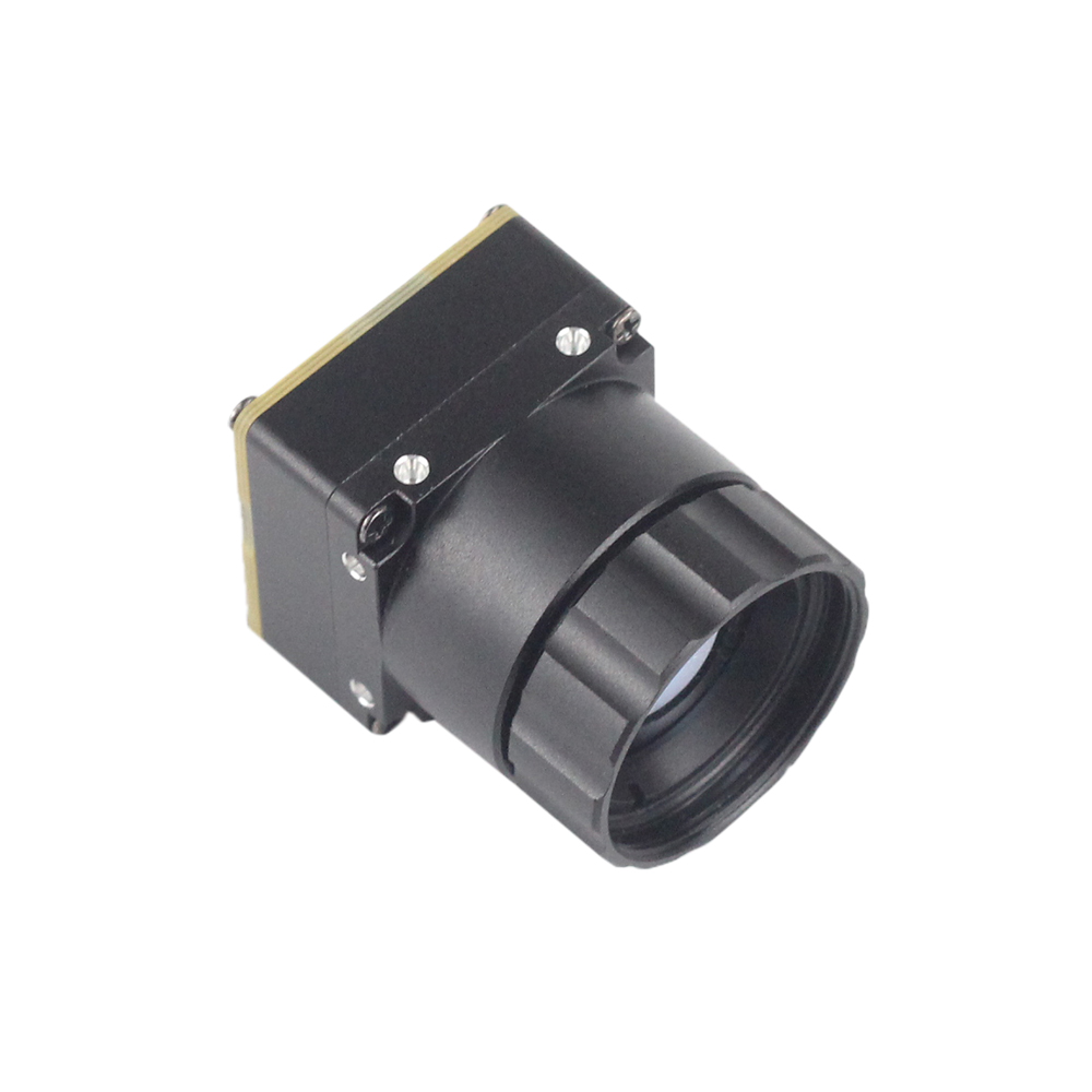
The Uncooled Mini 384*288 Thermal Camera Module For Drones is engineered for aerial payloads and small robotic deployments where mass, volume, and power consumption are constrained. Delivering 110,592 measurement pixels, this core provides clear thermal profiles for automated target tracking and structural diagnostics.
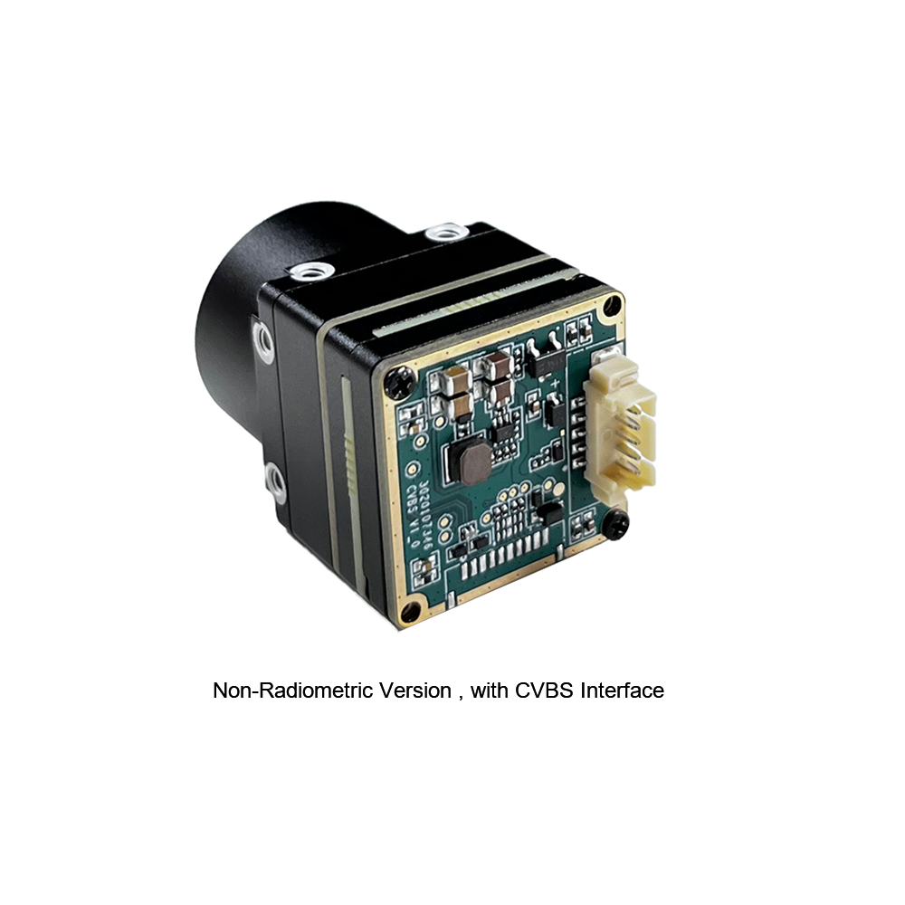
The module is designed for online temperature measurement in machine vision, equipment inspection, intelligent manufacturing, and airborne drone operations. Its low thermal mass allows it to stabilize quickly after power-on, while its integrated CVBS interface delivers an uncompressed, zero-latency analog feed for long-range transmission. For digital systems, the core provides direct temperature array outputs for local edge microcontrollers. Engineers building compact robotic payloads can explore additional design parameters in this high-resolution mini LWIR core guide.
3.3 Deep Dive: Megapixel 1280×1024 Scientific/Industrial LWIR Core
For applications requiring extended detection range, wide coverage, and fine spatial resolution, the High Resolution Uncooled Infrared 1280*1024 Thermal Imaging LWIR Camera provides 1.31 million continuous measurement pixels on a single focal plane array.
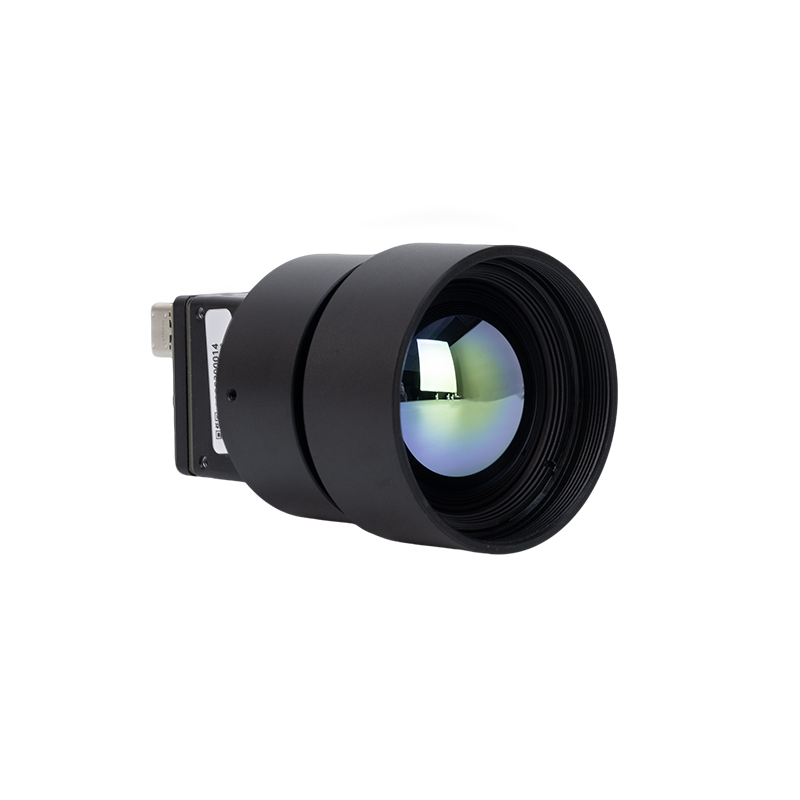
Paired with a dedicated 25mm prime lens, this system provides a wide field of view while maintaining a low IFOV. This allows operators to distinguish minute mechanical defects, structural anomalies, and distant targets across wide inspection zones without mechanical panning. In industrial assembly environments, the 1280×1024 array captures broad production scenes within a single frame, detecting subtle heat dissipation differences across components. Integrators can find detailed communication protocols and interface pinouts in this thermal imaging module system integration manual.
4. Edge AI, Embedded Protocols, and Drone/Robotic Payloads
Modern industrial installations require more than just streaming visual thermal imagery; they require processing raw digital radiometric arrays directly within autonomous edge devices.
4.1 Interface Selection: MIPI-CSI2, USB3, GigE Vision, and CVBS
Connecting a thermal imaging module to an embedded processor or edge computing node requires selecting the appropriate physical interface based on data rate, latency, and environmental constraints:
- ⚙️ MIPI-CSI2 (Camera Serial Interface): MIPI-CSI2 is the preferred interface for direct board-level system integration with embedded system-on-chip (SoC) architectures (such as NVIDIA Jetson, NXP i.MX8, or custom FPGA platforms). It transmits raw pixel data directly into the host processor's Image Signal Processor (ISP), bypassing protocol translation steps and minimizing latency. Using industrial-grade connectors from interconnect suppliers like TE Connectivity ensures signal integrity in high-vibration environments.
- ⚙️ GigE Vision / Industrial Ethernet: The standard interface for factory floor automation, process machinery, and fixed security installations. GigE Vision supports cable runs up to 100 meters over standard Cat6 copper lines with galvanic isolation, while adhering to GenICam and ONVIF communication standards.
- ⚙️ USB3 / UVC (USB Video Class): Widely used for desktop testing, laboratory setups, and rapid prototyping. USB3 offers plug-and-play connectivity and carries both power and high-bandwidth data over a single cable. For field deployments, locking screw connectors are recommended to prevent disconnections caused by mechanical vibration.
- ⚙️ Analog CVBS: While an older analog standard, CVBS remains valuable for airborne drone systems using analog video transmitters. It delivers low latency without digital compression artifacts, and maintains a viewable signal even as RF reception weakens. For tactical night-vision payloads, designers can reference the wiring approaches documented in this tactical thermal night vision integration module guide.
4.2 SWaP-C Optimization in Airborne Systems
Integrating thermal sensors into aerial drones requires managing Size, Weight, Power, and Cost (SWaP-C) constraints:
- ⚙️ Payload Mass: Every additional 50 grams of payload mass visibly degrades flight duration, demanding higher battery cell capacity and increasing overall take-off weight.
- ⚙️ Power Consumption: Sensor modules consuming more than 2.5 Watts place greater load on the flight platform's power distribution systems and generate internal heat that must be dissipated to maintain sensor accuracy.
- ⚙️ Optical Center of Gravity: The density of Germanium optics can pull a gimbal's balance point forward. Balancing the optical payload properly prevents motor strain, reduces stabilization errors, and avoids vibrations in dynamic flight conditions.
4.3 Processing Raw Temperature Arrays on Edge Microcontrollers
Industrial edge computing nodes typically process thermal imaging feeds using one of two methods:
The first method involves colorized video streams, such as 8-bit YUV or RGB feeds mapped to color palettes like Ironbow or White-Hot. While practical for human operators, these streams discard the underlying radiometric calibration, making them unsuitable for precise automated analytics.
The second method uses 14-bit or 16-bit raw radiometric data streams. Here, each pixel retains its raw digital value, which converts directly to an absolute temperature reading using the sensor's calibration parameters:
T_target = (Pixel_Value * Scale_Factor) - Calibration_Offset
Edge inference engines (such as TensorRT or ONNX Runtime) process these raw temperature arrays directly. By applying lightweight convolutional neural networks (CNNs) to absolute thermal data rather than visible light imagery, edge systems can reliably detect equipment overheating, fluid leaks, and personnel across variable lighting conditions.
5. What Is Actually Worth Buying? Selection Matrix for OEMs & Engineers
The thermal imaging market spans from $200 smartphone plug-in dongles to specialized cooled MWIR surveillance systems costing tens of thousands of dollars. Industrial procurement teams should use a structured evaluation approach to ensure hardware meets their operational requirements.
The "Do Not Buy" Warning: Sub-$400 Consumer Gadgets for Industrial Tasks
Low-cost consumer thermal cameras and smartphone accessories are designed for basic home inspections, such as locating drafty windows or checking plumbing runs. Using these devices for industrial testing, predictive maintenance, or robotic integration often leads to problems:
- ⚠️ Low Array Resolution: Sensors with resolutions of 80×60 or 160×120 pixels lack the spatial density required for industrial components. At moderate working distances, a single pixel covers an area larger than typical surface-mount electronics or terminal connections, diluting the thermal reading and masking potential faults.
- ⚠️ High NETD Noise Floors: Consumer units often have NETD ratings above 70 mK, making them unable to resolve subtle temperature differences in low-contrast environments.
- ⚠️ Thermal Drift and Stability: Budget modules often lack active thermal drift compensation and utilize plastic optical barrels. As the device warms up during operation, readings can drift by 5°C or more, making them unsuitable for reliable engineering sign-offs.
The Recommended Industrial Baseline: Core Specifications
For automated machinery, robotic payloads, and predictive maintenance programs, hardware selections should meet the following baseline standards:
- ✅ Native Resolution: Minimum 384×288 pixels for general diagnostics; 640×512 for standard field inspections; 1280×1024 for long-range surveillance or wide-area process monitoring.
- ✅ Thermal Sensitivity: ≤40 mK NETD at f/1.0, utilizing Vanadium Oxide (VOx) focal plane arrays.
- ✅ Frame Rate: Real-time frame rates (≥25 Hz to 50 Hz) are required for moving machinery and dynamic flight systems. 9 Hz modules should be limited to applications where international export restrictions mandate lower frame rates.
- ✅ Optics: Athermalized Germanium or Chalcogenide lenses featuring protective Diamond-Like Carbon (DLC) exterior coatings.
- ✅ Data Interface: Direct access to uncompressed 14-bit or 16-bit radiometric data via MIPI, USB3, or GigE Vision protocols.
- ✅ Operating Envelope: Rated for industrial operating temperatures from -20°C to +60°C (extended limits of -40°C to +85°C for aerospace deployments).

6. Deep-Dive Technical FAQ
How do thermal cameras actually work compared to standard night vision?
Are sub-$400 budget thermal cameras actually worth owning, or are they just gimmicks?
Can thermal camera modules be integrated over network protocols like Ethernet or mounted to drones?
7. Strategic Takeaway & Integration Roadmap
When selecting thermal imaging hardware, engineering teams should evaluate their technical requirements against these primary considerations:
- ✅ Pixel Resolution Over Digital Scaling: Choose a native focal plane array resolution that satisfies the Johnson criteria for your target distance, ensuring that critical objects cover multiple pixels for accurate temperature measurement.
- ✅ Sensor Material and Sensitivity: Prioritize Vanadium Oxide (VOx) microbolometers with an NETD of ≤40 mK to ensure the system can distinguish subtle temperature variations in low-contrast conditions.
- ✅ Radiometric Data Access: Verify that the camera architecture provides access to raw 14-bit or 16-bit digital temperature arrays if your project involves automated analytics, machine vision, or Edge AI processing.
- ✅ Environmental and Mechanical Integration: Ensure the lens assembly, housing, and interface connections match your operating environment, accounting for vibration, working temperature ranges, and payload mass constraints.
By balancing detector physics, optical materials, and interface requirements, systems integrators can select thermal imaging solutions that provide reliable, long-term radiometric performance across demanding industrial and airborne applications.
📚 References & Further Reading
- Industry Standard: TE Connectivity — Advanced Interconnect and Sensor Packaging Standards
- Industry Standard: Rising Optics — Precision Germanium and Chalcogenide Optical Manufacturing
- Related Guide: Thermal Imaging Module System Integration Manual
- Related Guide: High-Resolution Mini LWIR Core Guide for Drone Payloads
- Related Guide: Tactical Thermal Night Vision Integration Module Guide