Handheld Thermal Camera Guide: Sensor Specs, Field Performance & Pro Selection
2026年10月21日
Infrared Thermal Imaging Camera Guide: Real Resolution, Sensor Tech & Buying Truths
2026年10月22日
High-Resolution IR Thermal Camera Modules: Complete Industrial OEM Buying Guide
Precision thermal vision is no longer confined to bulky military hardware or high-cost lab equipment. For robotics engineers, drone payload designers, and industrial automation architects, integrating an uncooled IR thermal camera module directly into edge systems has become a baseline requirement for next-generation automated optical inspection (AOI), predictive maintenance, autonomous navigation, and intelligent perimeter defense. However, transitioning from off-the-shelf handheld diagnostic tools to embedded, board-level Long-Wave Infrared (LWIR) cores introduces complex engineering challenges—ranging from pixel pitch optimization and sensor chemistry selection to radiometric thermal calibration, low-latency streaming protocols (MIPI-CSI2, USB3, CVBS), and strict Size, Weight, Power, and Cost (SWaP-C) constraints.
Selecting the right thermal imaging engine requires evaluating sensor architectures, lens optics, and software image signal processing (ISP) pipelines. A sub-optimal choice can result in thermal drift, high Noise Equivalent Temperature Difference (NETD), spatial blur at high frame rates, or massive driver overhead on edge microprocessors. This comprehensive OEM buying guide deconstructs the underlying physics, core hardware criteria, real-world integration architectures, and commercial specifications of state-of-the-art LWIR modules—providing engineering and procurement teams with the technical blueprint required to specify, integrate, and deploy embedded thermal vision solutions at scale.
Table of Contents
- 👉 1. Physics of Uncooled Long-Wave Infrared (LWIR) Detection
- 👉 2. Key Architecture Metrics: Resolution, Pixel Pitch, and NETD
- 👉 3. Hardware Interface Selection for Embedded Systems: USB, MIPI, and CVBS
- 👉 4. Lens Optics and Field of View (FOV) Engineering
- 👉 5. Industrial OEM Benchmark: Mini 640 vs. MD Series 384
- 👉 6. System Integration Playbook: Drones, Machine Vision, & Predictive Maintenance
- 👉 7. Radiometric Calibration and Non-Uniformity Correction (NUC)
- 👉 8. Comprehensive OEM Buying Checklist & Troubleshooting Guide
- 👉 9. Frequently Asked Questions (FAQ)
1. Physics of Uncooled Long-Wave Infrared (LWIR) Detection
Understanding how an industrial IR thermal camera core captures non-visible energy requires analyzing thermal radiation physics, blackbody emission curves, and atmospheric transmission dynamics. All physical matter at temperatures above absolute zero (0 Kelvin or -273.15 degrees Celsius) continuously emits electromagnetic radiation as a fundamental consequence of molecular and atomic kinetic agitation. The spectral distribution and total radiant energy emitted by an object are governed by Planck’s Radiation Law, which describes the spectral radiance of an idealized blackbody emitter as a function of thermodynamic temperature and wavelength.
For industrial targets operating within normal terrestrial environmental envelopes—typically between -40 degrees Celsius and +500 degrees Celsius—the peak spectral radiant emittance calculated via Wien's Displacement Law falls precisely within the Long-Wave Infrared (LWIR) spectrum between 8 micrometers and 14 micrometers. Terrestrial atmospheric conditions present narrow transmission windows where atmospheric gases such as water vapor, carbon dioxide, and ozone do not fully absorb transmitted photons. The 8 to 14 micrometer atmospheric transmission window provides optimal operational clarity, remaining virtually immune to solar blinding, haze, particulate scattering in the Rayleigh scattering regime, and thick industrial smoke.
Emissivity represents the ratio of radiant energy emitted by a real-world material surface relative to a theoretical blackbody at identical temperature and wavelength. In real-world thermal monitoring environments, emissivity ranges from near zero to unity. High-emissivity targets, such as matte black polymers, carbon composites, vulcanized rubber, and flat painted surfaces, emit thermal radiation that correlates in a predictable, linear manner with their true thermodynamic core temperature. Conversely, low-emissivity surfaces, such as polished aluminum housings, bare copper busbars, and rolled stainless steel sheets, act as thermal mirrors. Instead of radiating intrinsic energy, they reflect background thermal signatures into the optical aperture. To achieve absolute measurement precision, system architects must select an IR thermal camera equipped with advanced onboard digital processing capable of compensating for surface emissivity, ambient background reflected apparent temperature, and atmospheric transmission attenuation in real time.
At the mechanical and physical heart of modern uncooled thermal imaging engines lies a Focal Plane Array (FPA) consisting of thousands of suspended microbolometers. Each microbolometer pixel features an infrared absorption membrane suspended above a silicon readout integrated circuit (ROIC) by micro-machined supporting legs, creating a vacuum-isolated thermal bridge. When incident infrared photons strike the absorption membrane, its physical temperature rises, inducing a measurable alteration in the electrical resistance of the integrated thermistor material. The underlying CMOS ROIC continuously interrogates this resistance shift across every array coordinate, translating electrical variances into digital raw counts representing thermal gradients.
OEM modules rely predominantly on two thin-film thermistor materials: Vanadium Oxide (VOx) and Amorphous Silicon (a-Si). Vanadium Oxide exhibits a superior Temperature Coefficient of Resistance (TCR), typically operating between -2.0 percent and -3.0 percent per Kelvin, coupled with an exceptionally low 1/f low-frequency electronic flicker noise floor. This chemical property gives VOx sensors an inherently lower thermal time constant, typically between 8 and 12 milliseconds, allowing rapid thermal reaction times without the ghosting artifacts common to older sensors. Amorphous Silicon, while historically advantageous for high-volume CMOS foundry fabrication compatibility, possesses a lower TCR (-1.5 percent to -2.5 percent per Kelvin) and exhibits higher internal thermal drift under changing environmental temperatures. For high-precision automated inspection, defense operations, and commercial drone payloads, Vanadium Oxide has emerged as the definitive material choice for uncooled microbolometer sensor fabrication.
Beyond material purity, packaging architecture dictates long-term detector survivability and measurement consistency. Because uncooled microbolometers rely on microscopic thermal isolation legs to prevent heat bleeding into the silicon substrate, any atmospheric gas molecules trapped within the sensor cavity will create parasitic conductive thermal paths. This degradation destroys detector responsivity and degrades the signal-to-noise ratio over time. Premier OEM cores utilize metallic or ceramic hermetic vacuum packaging sealed at sub-milliTorr pressures, reinforced by integrated chemical getter strips that scavenge outgassed hydrogen and trace volatile compounds over a multi-decade operational lifespan.
2. Key Architecture Metrics: Resolution, Pixel Pitch, and NETD
Configuring an embedded IR thermal camera core requires balancing spatial resolution, sensitivity thresholds, and temporal response. Over the past decade, thermal sensor architectures have shifted aggressively from legacy 25-micrometer and 17-micrometer pixel pitches down to modern 12-micrometer nodes, with 10-micrometer and 8-micrometer architectures actively emerging from specialized optoelectronic laboratories. For industrial OEM integration, 12 micrometers currently represents the engineering sweet spot across manufacturing yields, optical compatibility, and Size, Weight, and Power (SWaP) metrics.
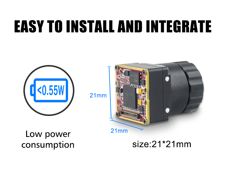
As pixel pitch decreases from 17 micrometers to 12 micrometers, the focal length required to achieve an identical Instantaneous Field of View (IFOV) decreases by roughly 30 percent. Because crystalline Germanium lenses represent between 40 percent and 60 percent of the total BOM cost and physical mass of a complete thermal engine, a smaller optical aperture directly lowers physical payload footprints and bill-of-materials expenses. Furthermore, a 640x512 array fabricated at a 12-micrometer pitch yields considerably more functional dies per semiconductor wafer than an older 17-micrometer equivalent, enabling vendors to produce miniature mechanical packages such as the 21mm x 21mm form factor utilized in stabilized micro-gimbals and handheld thermal scopes.
However, diminishing pixel sizes introduce critical optical physics constraints governed by the wave nature of light. At an operational wavelength of 10 micrometers, a high-quality F/1.0 Germanium lens generates an Airy disk diffraction pattern with a diameter of approximately 24.4 micrometers. Because this central optical diffraction spot spans multiple 12-micrometer pixels, high-end thermal optic designers must carefully optimize Modulation Transfer Function (MTF) performance across the entire optical train. Failure to match optical resolution to the microbolometer array results in severe spatial blur, optical cross-talk, and compromised radiometric accuracy along edge boundaries.
Noise Equivalent Temperature Difference (NETD) defines the fundamental signal-to-noise benchmark of an infrared sensor. NETD specifies the smallest incident temperature differential the detector can reliably register before the target signal becomes indistinguishable from the sensor's intrinsic electronic noise floor. Expressed in millikelvins (mK), an NETD under 50 mK represents standard commercial grade, while sensitivity ratings under 40 mK or 30 mK characterize premium industrial equipment. Sub-40mK sensitivity allows an automated inspection platform to detect micro-delaminations deep within composite aircraft wings, identify subtle subsurface insulation moisture ingress inside building envelopes, and isolate microscopic resistive anomalies across dense surface-mount PCB components before component failure occurs.
Evaluating motion performance in high-speed manufacturing or aerial scanning requires examining the sensor's thermal time constant alongside frame rate capabilities. The thermal time constant represents the time required for a microbolometer pixel to register 63.2 percent of an instantaneous step change in incident thermal flux. Typical VOx microbolometers achieve time constants between 8 and 12 milliseconds. If a drone platform or conveyor system moves too fast relative to this time constant, fine target edges exhibit residual thermal ghosting or smear. Furthermore, export control regimes such as the Wassenaar Arrangement restrict frame rates above 9 Hz for consumer export without extensive licensing. For robotic vision, high-speed automated sorting, and flight-critical gimbal stabilization, OEMs must specify high-frame-rate engines operating at 25 Hz, 30 Hz, 50 Hz, or 60 Hz to ensure smooth temporal tracking and rapid edge reaction loops.
3. Hardware Interface Selection for Embedded Systems: USB, MIPI, and CVBS
Connecting an uncooled IR thermal camera core to an embedded host processor—such as an NVIDIA Jetson Orin, Rockchip RK3588, Raspberry Pi Compute Module 4, or a dedicated industrial FPGA—requires selecting the optimal physical communication bus and video transmission protocol. System architects must weigh data throughput, processing overhead, cable length, physical weight, and latency when designing their digital interface pipeline.
Direct Mobile Industry Processor Interface (MIPI) Camera Serial Interface 2 (CSI-2) provides the optimal low-latency, point-to-point connection for embedded platforms and edge artificial intelligence engines. MIPI CSI-2 routes raw sensor frames directly across differential D-PHY lanes straight into the host processor's hardware Image Signal Processor (ISP) or internal RAM via Direct Memory Access (DMA). This architecture achieves ultra-low latency, typically under 5 milliseconds, completely bypassing the software protocol layers, USB serialization stages, and bridge-chip frame buffers that can delay closed-loop drone flight stabilization or high-speed robotic picking arms. Furthermore, MIPI CSI-2 delivers uncompressed 14-bit or 16-bit raw radiometric pixel streams (Y14/Y16) alongside synchronized frame metadata headers. This allows onboard neural network frameworks, such as YOLOv8 or RT-DETR running on an edge NPU, to process raw thermodynamic values directly rather than lossy, downsampled 8-bit RGB color maps. When routing high-speed differential MIPI pairs across multi-axis robotic joints or compact drone slip rings, specifying reliable interconnect hardware from trusted electronic component manufacturers like TE Connectivity ensures proper impedance matching, robust physical retention, and comprehensive EMI shielding.
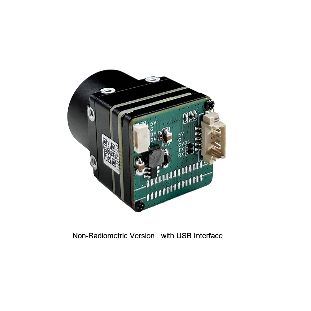
Industrial Universal Serial Bus (USB) connections, operating via USB 2.0 or high-speed USB 3.0 standards, leverage the universal USB Video Class (UVC) driver framework. This makes USB the preferred interface for rapid prototyping, laboratory diagnostic benches, and single-board computer architectures. A major advantage of USB-based thermal cores is complete plug-and-play driver support across standard operating systems, including Ubuntu Linux via Video4Linux2 (V4L2), Windows DirectShow and MediaFoundation, Robot Operating System (ROS / ROS 2), and Android. Beyond raw and processed video stream transmission, the USB protocol handles bidirectional command and control data using standard USB Control Endpoints or UVC Extension Units. Engineers can trigger Non-Uniformity Correction (NUC) shutter calibrations, adjust target emissivity parameters, switch internal pseudo-color palettes, and execute digital zoom commands over a single physical four-conductor wire or ruggedized USB Type-C assembly without routing dedicated auxiliary UART or I2C serial lines.
Composite Video Blanking and Sync (CVBS) provides an analog 75-ohm baseband video output formatted for standard NTSC or PAL legacy monitors. Although CVBS cannot transmit 14-bit radiometric digital temperature arrays, it remains valuable for specific real-world applications. Analog transmission features near-zero video latency and operates over simple coaxial wires without requiring host operating systems or boot times. This makes CVBS an ideal fallback or primary video feed for unencrypted drone analog First-Person View (FPV) transmitters, marine thermal displays, legacy security matrix switchers, and wearable tactical display goggles where instantaneous, lag-free situational awareness is essential.
4. Lens Optics and Field of View (FOV) Engineering
Unlike standard visible-light machine vision cameras that utilize precision borosilicate crown and flint glass optics, Long-Wave Infrared photons are completely absorbed by standard silicate glasses. As a result, infrared imaging optics must be fabricated from specialized infrared-transmissive crystalline semiconductor elements, such as Monocrystalline Germanium (Ge), Zinc Selenide (ZnSe), or synthetic Chalcogenide amorphous glass compounds.
Monocrystalline Germanium serves as the historical optical benchmark for high-performance infrared imaging due to its high refractive index of approximately 4.0 at an operational wavelength of 10 micrometers. This elevated refractive index allows optical engineers to design ultra-compact lens elements with shallow surface curvatures, minimizing optical aberrations while maintaining large apertures (F/1.0 to F/1.1) to gather maximum thermal flux. However, Germanium exhibits high thermal sensitivity. As temperatures climb toward +100 degrees Celsius, free-carrier optical absorption inside raw Germanium increases exponentially, causing the optical crystal to lose transparency and turn opaque to LWIR transmission. To counter this limitation and lower production costs for high-volume commercial production, modern lens manufacturers combine precision-molded Chalcogenide glass elements with specialized Germanium components. Chalcogenide glasses possess a lower thermo-optic coefficient (dn/dT), allowing engineers to produce mechanically and optically athermalized lens assemblies. These assemblies maintain sharp focal integrity across extreme industrial temperature ranges (-40 degrees Celsius to +80 degrees Celsius) without requiring power-consuming motorized autofocus mechanisms.
Selecting the optimal focal length requires balancing the horizontal Field of View (HFOV), vertical Field of View (VFOV), and Instantaneous Field of View (IFOV). IFOV defines the angular spatial resolution of an individual pixel, calculated as the physical pixel pitch divided by the optical focal length. Multiplying the IFOV by the target distance determines the physical spot size projected onto a single microbolometer detector. For accurate industrial temperature measurement, a thermal target must completely cover a minimum measurement spot of at least 3x3 or 4x4 contiguous pixels (Measurement Field of View, MFOV). This ensures that optical blur and energy dispersion at target boundary edges do not artificially dilute the measured temperature values. Engineers evaluating core lens compatibility and system layouts can review detailed optical configurations in our comprehensive product catalog.
Matching the lens focal length to the operational scenario determines the platform's diagnostic capability. Ultra-wide-angle lenses with focal lengths between 5mm and 9.1mm provide wide field coverage ranging from 48 degrees to 82 degrees. These lenses are ideal for close-quarter robotics, autonomous vehicle obstacle avoidance, building interior audits, and enclosed electrical switchgear cabinet inspection. Mid-range lenses between 13mm and 25mm offer narrower horizontal fields of view (roughly 17 degrees to 33 degrees on a 640x512 array), making them the preferred choice for industrial aerial inspections, medium-altitude drone mapping, smart traffic management, and warehouse asset protection. Telephoto lenses ranging from 50mm to 150mm reduce fields of view to narrow angles between 2 degrees and 8 degrees. These telephoto optics are essential for ultra-long-range surveillance, coastal perimeter defense, high-voltage electrical transmission tower inspection, and cross-border critical infrastructure security.
5. Industrial OEM Benchmark: Mini 640 vs. MD Series 384
To assist system architects in selecting the ideal thermal engine for their embedded applications, the following technical evaluations profile two flagship uncooled microbolometer cores from Purpleriver: the ultra-compact Mini 640 and the versatile MD Series 384.
Product Showcase 1: Purpleriver Mini 640 LWIR Camera Core

Mini Uncooled LWIR USB 640*512 Thermal Imaging Camera Core Module
The Purpleriver Mini 640 core delivers high-definition infrared imaging within an ultra-compact mechanical envelope. Designed specifically for drone integration similar to enterprise DJI payloads, lightweight stabilized aerial gimbals, and SWaP-constrained industrial inspections, this module features sharp image presentation and stable environmental performance. Measuring just 21mm by 21mm, it provides native 640x512 resolution with an optional 640x480 operating mode. Its broad lens ecosystem ranges from ultra-wide 5mm optics to long-range 150mm telephoto configurations, ensuring versatility across varied operating environments.
- ✅ Resolution: Native 640 × 512 high-density array (Optional 640 × 480 legacy video format)
- ⚙️ Form Factor: Ultra-miniature 21mm × 21mm board footprint for weight-critical systems
- ⚙️ Optics Portfolio: 5mm, 9mm, 13mm, 18mm, 35mm, 50mm, 75mm, 100mm, and 150mm lens selections
- ✅ Target Applications: Aerial gimbal stabilization, compact drone payloads, robotic AOI, and night-vision sights
Product Showcase 2: Purpleriver MD Series 384 Infrared Thermal Module
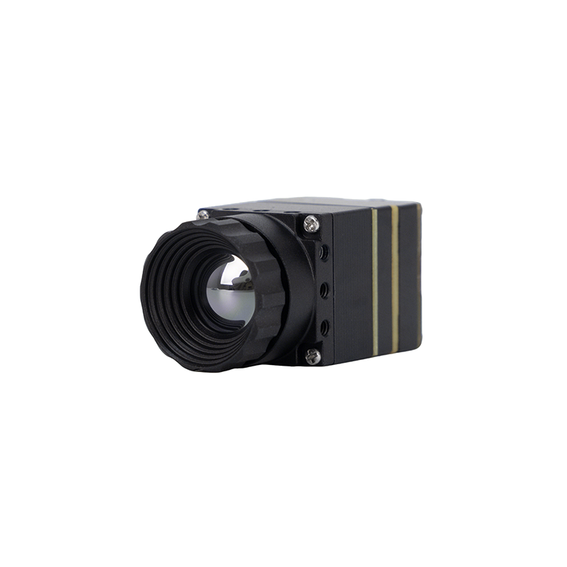
MD Series 384×288 Uncooled Infrared Thermal Camera Module
The Purpleriver MD Series thermal module is engineered for industrial precision across perimeter security, temperature monitoring, and multi-rotor drone payloads. Built around an uncooled infrared detector with an industry-standard 12μm pixel pitch, it delivers high thermal sensitivity and crisp edge delineation. Designed for plug-and-play operation, the module offers multiple hardware interfaces (MIPI, USB, and CVBS) to accelerate integration across custom carrier boards. Developed by an engineering team with backgrounds from the Hong Kong University of Science and Technology and former Huawei HiSilicon architects, the MD Series supports deep OEM/ODM firmware and hardware customization to meet exact application requirements.
- ✅ Resolution & Pitch: 384 × 288 active pixel matrix with advanced 12μm microbolometer pitch
- ⚙️ Tri-Bus Interfaces: Native hardware support for Direct MIPI CSI-2, USB 2.0/3.0, and Analog CVBS
- ✅ Engineering Pedigree: Developed by HKUST and ex-Huawei HiSilicon semiconductor architects
- ⚙️ OEM Customization: Deep board-level, FPGA pipeline, and firmware driver customization on demand
When engineering high-reliability aerospace gimbals, smart security nodes, or automated machinery, OEM supply chains should source directly from vetted manufacturing channels such as KUYANG to ensure end-to-end trace auditing, component binning compliance, and dependable lead times.
| Hardware Specification | Purpleriver Mini 640 LWIR Core | Purpleriver MD Series 384 LWIR Core |
|---|---|---|
| Detector Technology | Uncooled VOx Microbolometer | Uncooled VOx Microbolometer |
| Array Resolution | 640 × 512 (Optional 640 × 480) | 384 × 288 Pixels |
| Pixel Pitch | 12 μm | 12 μm |
| Spectral Response | 8 μm to 14 μm (LWIR) | 8 μm to 14 μm (LWIR) |
| Thermal Sensitivity (NETD) | ≤ 40 mK (@25°C, F/1.0, 50Hz) | ≤ 40 mK (@25°C, F/1.0, 50Hz) |
| Chassis Dimensions | Mini-Size: 21mm × 21mm | Compact Design: 21mm × 21mm |
| Hardware Video Output | USB 2.0 (UVC), Analog CVBS | MIPI-CSI2, USB 2.0/3.0, CVBS |
| Lens Focal Length Options | 5, 9, 13, 18, 35, 50, 75, 100, 150 mm | 5, 9, 13, 18, 35, 50 mm Options |
| Environmental Adaptability | High stability, industrial-grade range | Industrial-grade operating range |
| OEM Engineering Support | Complete hardware & mount customization | Ex-Huawei HiSilicon & HKUST Team Customization |
6. System Integration Playbook: Drones, Machine Vision, & Predictive Maintenance
Integrating an embedded IR thermal camera core requires careful hardware, electrical, and algorithmic configuration. System architectures vary significantly depending on whether the core is mounted inside an aerial UAV payload, an automated machine vision cell, or a fixed predictive maintenance enclosure.
Mounting an uncooled LWIR core into an aerial drone gimbal (such as enterprise DJI configurations or custom multi-rotor UAVs) introduces strict SWaP-C constraints. At just 21mm by 21mm, the Purpleriver Mini 640 allows designers to engineer 3-axis brushless gimbals weighing under 180 grams complete with mounting hardware and dampeners. Minimizing payload mass lowers drone battery consumption, directly extending flight operational windows. Thermal dissipation requires dedicated architectural planning. Because uncooled microbolometers operate without active internal thermoelectric coolers, external temperature shifts—such as air turbulence and rotor downwash—can introduce thermal gradients across the core's chassis. If left unmanaged, these gradients cause radiometric drift and visual shading across the Focal Plane Array. Payload engineers should mechanically mount the module's exterior casing to an internal aluminum chassis using high-conductivity thermal gap pads (greater than 6 W/m-K) to route heat away from the internal readout circuitry. To explore tactical multi-sensor aerial payloads and outdoor tracking systems, review our technical guide on hunting & outdoor observation artifacts.
For automated defect detection and machine vision applications, standard 8-bit compressed video formats (such as H.264 or standard RGB conversions) are insufficient for automated quality inspection. Standard video compression discards absolute temperature metadata in favor of visual contrast for human viewing. Industrial automated optical inspection requires true 14-bit or 16-bit radiometric digital data pipelines. In this configuration, the host platform ingests the full uncompressed digital count array over MIPI CSI-2 or USB endpoints. Each individual pixel represents a raw radiometric value directly mapped to factory calibration polynomials stored in the camera's onboard non-volatile memory.
Automated software architectures apply target emissivity and distance equations directly to this raw 14-bit matrix, generating a floating-point temperature map in memory. Computer vision libraries, such as OpenCV or edge AI models running via TensorRT, can then segment the frame into discrete Regions of Interest (ROIs). These models continuously calculate maximum, minimum, and standard deviation temperatures across specific regions—such as inspecting surface-mount component soldering on a PCB, detecting thermal anomalies in EV battery pouch cells, or verifying heating elements on automotive windshields. For architectural layouts and digital processing schematics, see our technical article on digital thermal camera cores architecture.
In fixed continuous predictive maintenance deployments—such as electrical substations, data center server racks, and petrochemical processing facilities—the thermal core acts as an intelligent visual transducer. Fixed installations must maintain continuous connectivity with Supervisory Control and Data Acquisition (SCADA) platforms, PLCs, and Industrial Internet of Things (IIoT) management software. By utilizing the tri-bus capability of cores like the Purpleriver MD Series 384, developers can stream analog CVBS video to on-site operator safety monitors while simultaneously streaming digital radiometric arrays over USB or MIPI to an edge gateway. This edge gateway processes the thermal metrics, monitors user-defined threshold limits, and transmits automated alerts over Modbus TCP, MQTT, or Profinet industrial networking protocols if an asset exceeds acceptable thermal operating thresholds.
To successfully bring an edge thermal inspection system from bench prototype to continuous 24/7 industrial deployment, engineers must structure their hardware and software integration roadmap across clear milestones:
- ⚙️ Mechanical Thermal Decoupling: Mount the core chassis using low-conductivity standoffs while securing a dedicated, uninhibited thermal conduction strap from the core's primary heat spreader directly to the system's external anodized aluminum heatsink.
- ⚙️ Clean Power Rail Regulation: Implement dedicated low-dropout (LDO) linear regulators with high Power Supply Rejection Ratios (PSRR > 70 dB at 100 kHz) to feed the microbolometer analog front end, isolating it from high-frequency DC-DC switching ripple.
- ⚙️ Kernel-Level Pipeline Ingestion: Bind the core's raw video stream via Video4Linux2 subdevices or custom V4L2 drivers to expose raw 14-bit or 16-bit frames directly into DMA ring buffers, eliminating unnecessary user-space memory copies.
- ⚙️ Algorithmic Radiometric Mapping: Implement onboard or edge GPU shader passes to compute Planck temperature polynomials in real time, converting incoming raw counts into Kelvin or Celsius float arrays before feeding vision classification models.
7. Radiometric Calibration and Non-Uniformity Correction (NUC)
Due to microscopic manufacturing tolerances inherent in thin-film semiconductor fabrication, individual microbolometer pixels exhibit subtle variations in thermal responsivity and dark-current offset. Left uncorrected, this uneven response produces Fixed Pattern Noise (FPN), visible as severe vertical and horizontal striping across the thermal image. Non-Uniformity Correction (NUC) represents the signal processing pipeline designed to eliminate this spatial noise and ensure accurate temperature output across every pixel on the array.
Mechanical shutter-based NUC represents the traditional method for correcting drift in field deployments. Periodically, or when internal temperature thermistors register a significant thermal delta, a tiny motorized mechanical paddle closes over the sensor array for 200 to 500 milliseconds. This shutter presents a uniform temperature target to every microbolometer detector. The onboard processor reads this reference image and recalibrates the individual pixel offset matrix to restore image uniformity. While mechanical shutter correction is effective, the physical freeze interrupts video transmission. This momentary pause can be problematic for high-speed tracking systems, flight-critical drone control loops, or automated manufacturing sorting conveyors.
To overcome this limitation, advanced industrial modules like the Purpleriver Mini 640 and MD Series incorporate advanced Shutterless Scene-Based Non-Uniformity Correction (SBNUC) algorithms. SBNUC continuously analyzes natural platform and scene motion across consecutive frames alongside internal module temperature sensor data. By applying statistical motion analysis, the processor computes and updates the non-uniformity offset matrix in software. This eliminates the need to cycle a mechanical shutter, providing an uninterrupted, non-freezing thermal video feed essential for automated machine vision systems and fast-moving autonomous platforms.
Laboratory calibration of an IR thermal camera core relies on a mathematical process known as Two-Point Calibration. The core is positioned in front of a wide-aperture high-precision cavity blackbody emitter set to a low reference temperature (T1), where the raw digital counts for every coordinate are recorded into memory. The emitter is then adjusted to a higher reference temperature (T2), and the corresponding pixel matrix is recorded. By evaluating the delta in output against the known radiated thermal flux, factory calibration systems generate a two-dimensional Gain Matrix and Offset Matrix. These calibration matrices are written directly into the core module’s onboard non-volatile EEPROM. During real-time field operation, the integrated Image Signal Processor uses these values to calculate a corrected digital count for each pixel at the sensor's native frame rate, ensuring consistent radiometric accuracy across varied ambient environments.
8. Comprehensive OEM Buying Checklist & Troubleshooting Guide
Before finalizing component selection and deploying capital for large production volumes, engineering procurement teams should review this validation checklist to verify core specifications and avoid common integration pitfalls.
- ✅ Verify True Spectral Bandwidth: Confirm the focal plane array is genuinely engineered and coated for the 8μm to 14μm Long-Wave Infrared band, incorporating hard carbon or diamond-like optical window coatings to block parasitic Near-IR and Mid-IR stray light.
- ✅ Validate Export Frame Rate Compliance: Cross-check target deployment countries against export control regulations (such as Wassenaar dual-use protocols) to determine whether an unrestricted 9 Hz engine or an authorized 25 Hz / 30 Hz / 50 Hz high-speed core is required.
- ✅ Confirm Optomechanical Athermalization: Ensure the lens barrel housing combines materials with complementary thermal expansion rates (such as Chalcogenide glass elements seated within precisely calculated aluminum/invar mechanical housings) to eliminate manual refocusing over -40°C to +80°C.
- ✅ Evaluate Raw Radiometric Stream Availability: Ensure the core firmware natively streams 14-bit or 16-bit uncompressed digital data (Y14/Y16) via MIPI or USB rather than restricting output to 8-bit AGC pseudo-color video streams.
Engineers frequently encounter integration issues that can compromise the performance of an otherwise high-grade thermal sensor. Resolving these challenges requires systematic electrical and mechanical isolation techniques:
- ⚙️ Resolving Housing Thermal Shading: If an uncooled core is integrated near high-wattage components—such as power management ICs or edge NPUs—asymmetrical heat conducts into one side of the sensor housing. This creates internal thermal gradients that manifest as dark vignetting or lopsided color gradients across the image. Resolution: Isolate mounting brackets using FR4 or ceramic washers, insert an internal thermal shield, and direct board-level heat exhaust away from the microbolometer housing.
- ⚙️ Compensating for Cosine-Fourth Lens Vignetting: Broad-angle Germanium optical assemblies experience natural edge luminance drop-off governed by the Cosine Fourth Law of illumination falloff. This causes periphery pixels to register cooler apparent temperatures than center pixels when pointing at an isothermal flat-field surface. Resolution: Verify that the camera core's ISP firmware provides built-in flat-field correction (FFC) tables tuned specifically to the attached lens model to digitally normalize corner pixel gains.
- ⚙️ Mitigating High-Frequency EMI Coupling: Pulse-width modulation (PWM) switching frequencies from drone electronic speed controllers (ESCs) and brushless motors radiate noise that couples into the microbolometer's high-impedance ROIC analog amplifiers, producing faint, rolling horizontal lines across the display. Resolution: Route digital signals through balanced differential MIPI pairs, enforce a single-point star ground between the thermal core and carrier board, and encase interconnect ribbon cables within continuous, grounded copper shielding tape.
9. Frequently Asked Questions (FAQ)
Can an IR thermal camera replace a standard handheld IR thermometer?
What is the practical difference between infrared photography and an IR thermal camera?
Why should engineers integrate an OEM thermal core module instead of commercial handheld thermal cameras?
📚 References & Further Reading
- Industry Standard: High-reliability interconnects and aerospace cabling architectures specified via TE Connectivity
- Industry Standard: Verified microbolometer engine manufacturing and industrial module production by KUYANG
- Related Guide: Explore deep architectural insights into internal sensor hardware in our guide on digital thermal camera cores architecture
- Related Guide: Review tactical integration strategies and multi-sensor aerial drone operations in our analysis of hunting & outdoor observation artifacts
- Related Guide: Browse the full portfolio of embedded uncooled microbolometers in our comprehensive product catalog