Thermal Camera for Android: Pro Smartphone Attachments vs. Standalone Modules Guide
2026年10月23日

The Ultimate Thermal Imaging Device Guide: Pro Performance, Edge AI & Practical ROI
Industrial predictive maintenance, aerial autonomous inspection, and mission-critical perimeter security have reached an unprecedented technological tipping point. Modern enterprise facilities can no longer afford the costly operational downtime, catastrophic electrical arc flashes, or undetected thermal runaway events inherent to legacy spot radiometers and intermittent visual checks. The modern thermal imaging device has transformed from an exotic, prohibitively expensive diagnostic tool into an indispensable, continuously monitoring edge sensor. Driven by aggressive breakthroughs in uncooled microbolometer fabrication, sub-30 millikelvin (mK) thermal sensitivity, and embedded deep-learning processors, today’s long-wave infrared (LWIR) systems convert invisible radiant flux into real-time, quantitative radiometric telemetry capable of driving complex automated workflows.
Deploying infrared hardware at scale requires navigating complex engineering trade-offs between optical physics, sensor architecture, and data orchestration. Selecting the right platform is far more nuanced than matching an equipment budget to raw pixel count; it requires balancing sensor pitch, Field of View (FOV), Instantaneous Field of View (IFOV), lens transmission efficiency, and edge compute interfaces. Whether integrating high-definition radiometric sensors into automated assembly lines or deploying ultralight aerial thermal payloads for utility corridor mapping, engineers and system architects need unambiguous technical parameters to secure maximum Return on Investment (ROI) and minimize Total Cost of Ownership (TCO). This comprehensive guide unpacks the underlying physics, architectural metrics, edge intelligence workflows, and industrial hardware specifications defining the modern thermal imaging landscape.
Table of Contents
- 👉 1. Foundational Physics: Microbolometer Arrays, Emissivity, and LWIR Transmission
- 👉 2. Core Sensor Metrics: NETD, Spatial Resolution, Pixel Pitch & Refresh Rates
- 👉 3. Edge AI Convergence: Autonomous Anomaly Detection & False-Positive Elimination
- 👉 4. Industrial Hardware Benchmarks: High-Resolution Cores vs. Ultra-Compact UAV Modules
- 👉 5. Autonomous Mobile Platforms: Integrating LWIR Payloads onto Drones & Robotics
- 👉 6. B2B Economic Impact: Calculating Predictive Maintenance ROI and TCO
- 👉 7. Calibration Protocols: Non-Uniformity Correction (NUC) and Radiometric Drift
- 👉 8. Deep-Dive Technical FAQ
1. Foundational Physics: Microbolometer Arrays, Emissivity, and LWIR Transmission
Every thermal imaging device operates on the fundamental physical reality that all matter possessing a temperature above absolute zero (0 Kelvin or -273.15°C) emits electromagnetic radiation proportional to its intrinsic thermodynamic state. Within the broader electromagnetic spectrum, visible light occupies the narrow 0.38 µm to 0.75 µm band, flanked by Near-Infrared (NIR) extending to 1.4 µm and Short-Wave Infrared (SWIR) spanning 1.4 µm to 3.0 µm. While Mid-Wave Infrared (MWIR) covers the 3.0 µm to 5.0 µm region—often utilized in high-speed, cryogenically cooled defense sensors—industrial optoelectronic diagnostics predominantly rely on the Long-Wave Infrared (LWIR) atmospheric transmission window between 8.0 µm and 14.0 µm. Within this specific spectral band, atmospheric attenuation caused by airborne water vapor and carbon dioxide absorption reaches localized minima, enabling uncooled thermal sensors to accurately capture passive surface thermal emissions across substantial atmospheric paths without significant atmospheric scattering.
Quantifying radiant energy begins with Planck's Radiation Law, which describes the spectral radiance emitted by an idealized blackbody as a function of wavelength and absolute thermodynamic temperature. Integrating Planck's distribution across all wavelengths yields the classical Stefan-Boltzmann Law, which states that total radiant emittance is directly proportional to the fourth power of absolute temperature, scaled by the Stefan-Boltzmann constant and the surface emissivity factor. In real-world industrial environments, materials rarely behave as perfect blackbodies with an emissivity of 1.0. Instead, practical targets are classified as "graybodies" with emissivity values ranging anywhere from 0.02 to 0.98. Highly polished metals, such as bare copper busbars, machined aluminum housings, and stainless steel pipework, display exceptionally low emissivity—typically between 0.05 and 0.20. Consequently, these materials act as infrared mirrors, reflecting radiant heat from surrounding ambient equipment and operational technicians directly into the camera optics, which leads to catastrophic measurement errors if left uncompensated.
To extract accurate thermal telemetry from industrial scenes, modern radiometric thermal cores integrate sophisticated mathematical compensation pipelines directly into their firmware. When configured by the user or an automated supervisory system, the device dynamically balances the fundamental radiation conservation equation: total incident radiation received by the sensor array equals emitted radiation plus reflected radiation plus transmitted radiation. By capturing parameters such as target emissivity, ambient background reflected temperature, target distance, relative atmospheric humidity, and internal lens transmission losses, the camera's processing engine isolates the true radiant signature of the asset under test. As detailed in comprehensive academic overviews of Wikipedia Thermal Imaging fundamentals, modern uncooled focal plane arrays (FPAs) consist of micro-machined bridge structures typically fabricated from Vanadium Oxide (VOx) or Amorphous Silicon (a-Si). These microbolometers absorb incident LWIR photons, causing a measurable change in their electrical resistance via their negative temperature coefficient of resistance (TCR). The Read-Out Integrated Circuit (ROIC) bonded beneath the microbolometer matrix reads these resistance shifts as analog voltages, digitizing them into high-resolution raw counts that map the target's absolute thermal distribution.
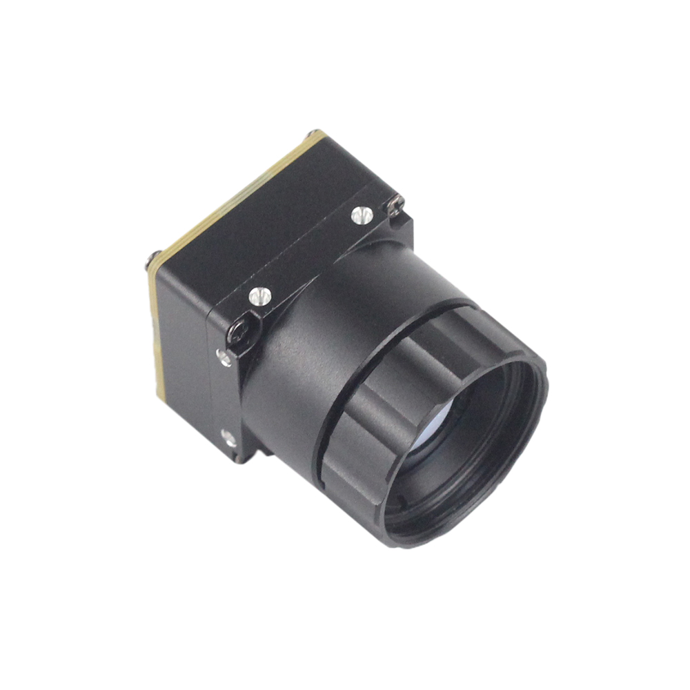
Vanadium Oxide technology has emerged as the premier material for high-performance industrial radiometric modules due to its superior TCR characteristics and lower intrinsic 1/f noise floor compared to older amorphous silicon architectures. Because uncooled VOx microbolometers operate at ambient room temperatures without bulky, power-hungry cryogenic stirling coolers, they represent the modern benchmark for Size, Weight, and Power (SWaP) optimization in commercial automation, unmanned aerial payloads, and long-term remote facility surveillance.
The microbolometer absorption process relies on precise structural engineering. Each pixel suspended on the ROIC substrate is held aloft by microscopic silicon nitride legs that minimize thermal conduction to the surrounding package. When LWIR photons strike the absorbing layer, the temperature of this suspended thermal mass rises by tiny fractions of a millikelvin. The speed at which a pixel can register this change and subsequently cool back down determines the thermal time constant of the detector—typically between 8 and 14 milliseconds. A shorter time constant permits faster frame capture without thermal ghosting or smear, making high-speed industrial process monitoring and rapid drone flyovers technically viable without degrading radiometric precision.
2. Core Sensor Metrics: NETD, Spatial Resolution, Pixel Pitch & Refresh Rates
Selecting and evaluating an industrial-grade thermal imaging device requires engineering teams to balance four interdependent, deeply critical electro-optical metrics. Compromising on any single architectural parameter directly impacts data fidelity, spatial accuracy, and actionable fault detection.
Noise Equivalent Temperature Difference (NETD): Expressed in millikelvins (mK), NETD represents the primary benchmark of a thermal sensor's sensitivity. It formally defines the smallest temperature delta that the microbolometer can distinguish from its own electronic and thermal noise floor. An industrial-grade sensor typically exhibits an NETD of less than 50 mK, which is sufficient for detecting macroscopic electrical overloads, mechanical bearing friction, and gross insulation breaks. However, advanced diagnostic applications—such as identifying delamination in aerospace composites, detecting latent moisture accumulation inside building facades, or evaluating micro-watt heat dissipation across multi-layer printed circuit boards—demand precision cores rated at sub-30 mK or sub-40 mK. A lower NETD value translates directly into higher signal-to-noise ratios (SNR), crisper thermal edge definition, and the ability to extract meaningful data from scenes with extremely narrow temperature variations.
Spatial Resolution and the Instantaneous Field of View (IFOV): Spatial resolution defines the absolute horizontal and vertical pixel matrix of the focal plane array, typically scaling from basic 256×192 sensors up to standard 640×512 arrays and high-definition 1280×1024 mega-pixel cores. However, spatial resolution alone cannot determine whether an optic can accurately measure a distant target. System architects must calculate the Instantaneous Field of View (IFOV), which represents the geometric angular footprint projected by a single microbolometer pixel through the optical lens assembly:
IFOV (in milliradians) = Pixel Pitch (d) / Focal Length (f)
While an asset anomaly might be detectable if its thermal signature covers a single pixel (Detection IFOV), calculating a dependable, uncorrupted radiometric temperature value requires the target to completely fill a minimum area of 3×3 or 4×4 continuous pixels on the sensor array. This critical metric is termed the Measurement Field of View (MFOV). Deploying an undersized sensor or an optic with too short a focal length results in optical "spot size blurring," where the background ambient radiation bleeds into the measurement pixel, leading to severe temperature under-reporting that can cause dangerous electrical switchgear failures to go entirely unnoticed.
Pixel Pitch Evolution: The physical dimensions of individual microbolometer pixel structures have contracted rapidly over the past decade. Where legacy industrial arrays relied on 17 µm or 25 µm pixel spacing, modern high-density sensors feature 12 µm architectures. Reducing the pixel pitch to 12 µm allows manufacturers to double or triple pixel density on a smaller silicon die. This design shift dramatically reduces the physical diameter and optical mass of the required Germanium lenses, yielding lighter, more compact sensor packages that are ideal for weight-sensitive drone gimbals. However, smaller pixel areas capture fewer total LWIR photons per integration period. To preserve high thermal sensitivity (low NETD) across 12 µm arrays, manufacturers must employ advanced VOx thin-film deposition techniques, high fill-factor optical cavity microstructures, and specialized readout circuit designs that curb readout amplifier noise.
Temporal Refresh Rates and Export Controls: Frame refresh rates directly dictate dynamic tracking capabilities. Standard low-end or export-unrestricted thermal cores operate at frame rates of 9 Hz or lower. While 9 Hz engines suffice for stationary tripods, slow handheld thermography, and basic fluid tank level monitoring, they suffer severe motion blur, spatial tearing, and delayed alarms when deployed on dynamic robotic crawlers, aerial drones, or automated high-speed conveyor belts. Professional industrial operations utilize high-speed 25 Hz, 30 Hz, or 50 Hz sensor engines. These refresh rates provide the fluid visual rendering, stable tracking metrics, and real-time analytical capabilities required to interface with automated factory lines or airborne guidance architectures.
3. Edge AI Convergence: Autonomous Anomaly Detection & False-Positive Elimination
Legacy continuous infrared monitoring networks relied almost exclusively on static radiometric tripwires, such as asserting a supervisory SCADA alarm whenever any isolated pixel exceeded a hardcoded threshold of 80°C. In live industrial environments, these rudimentary logic loops generate overwhelming volumes of false alarms. Passive solar loading reflecting off metallic structural beams, transient exhaust plumes from passing transport vehicles, and routine operational load spikes on large induction motors continuously trip uncalibrated sensors. This alert fatigue frequently drives control room technicians to bypass safety interlocks entirely, leaving assets vulnerable to unmonitored catastrophic failures.
The contemporary paradigm couples high-resolution, uncooled thermal imaging hardware directly with embedded edge computing intelligence. Instead of offloading high-bandwidth radiometric streams across congested enterprise local area networks to remote cloud servers, modern deployments execute inference tasks locally. Developers frequently prototype these intelligent architectures using open embedded hardware and rapid prototyping platforms like Arduino, pairing edge microcontrollers with low-power neural network accelerators before deploying enterprise-grade carrier boards. By deploying lightweight, hardware-accelerated Convolutional Neural Networks (CNNs) directly at the sensor level, edge systems revolutionize thermal telemetry processing:
- ⚙️ Autonomous Object Classification and Semantic Heat Masking: Modern deep-learning models, optimized for low-power edge deployment via TensorRT or ONNX runtimes, concurrently analyze contextual spatial features alongside thermal values. The edge model identifies and segments distinct scene components—classifying high-voltage disconnect switches, transformer bushings, fluid couplings, human personnel, and mobile ground equipment. Consequently, the edge system applies tailored radiometric logic to specific semantic regions. A human walking through a substation switchyard is dynamically ignored by the temperature tracking pipeline, while the transformer bushing immediately adjacent is continuously scrutinized against precise, load-compensated operating baselines.
- ⚙️ Dynamic Contextual Radiometry: Assets operating under varying production cycles require dynamic, contextual alerting rather than fixed thresholds. Intelligent edge algorithms continuously ingest external telemetry—such as motor drive amperage, rotational RPM, ambient meteorological conditions, or overall grid distribution loads—via fieldbus protocols like Modbus TCP or OPC UA. The onboard processor calculates an expected thermal equilibrium envelope for the asset in real time. If a bearing operates at 65°C under maximum mechanical torque, the edge model recognizes the condition as nominal. Conversely, if an identical 65°C measurement is detected while the unit is idling, the system immediately recognizes anomalous friction and flags an early-stage mechanical bearing failure before irreversible damage occurs.
- ⚙️ Thermal Gradient Dynamics and False-Positive Mitigation: Edge vision models analyze the physical behavior and mathematical derivative of thermal patterns over time (ΔT/Δt). True electrical resistance failures, such as loose junction lugs or corroded contact faces, generate heat according to Joule's First Law. This heat conducts outward across mechanical structures following predictable thermal conduction profiles governed by Fourier's Law. In contrast, non-fault artifacts—such as ambient reflections or localized sunlight glint—display razor-sharp boundaries, uniform geometric profiles, and nearly instantaneous temperature shifts when the angle of incidence alters. By evaluating spatial gradient morphology and thermal decay curves, edge AI nodes reliably filter out environmental artifacts, ensuring plant operators receive actionable notifications with exceptionally low false-positive rates.
4. Industrial Hardware Benchmarks: High-Resolution Cores vs. Ultra-Compact UAV Modules
Real-world industrial demands require selecting hardware tailored to the mechanical, spatial, and optical requirements of the deployment environment. Below, we examine two industrial thermal platforms that address complementary operational profiles: fixed high-precision facility diagnostics and agile autonomous aerial inspection.
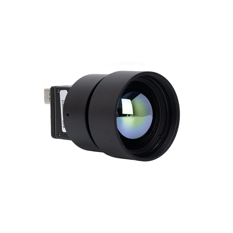
High Resolution Uncooled Infrared 1280*1024 Thermal Imaging LWIR Camera
Engineered for mission-critical fixed monitoring, scientific research testbenches, and long-range utility perimeter security, the High Resolution Uncooled Infrared 1280*1024 Thermal Imaging LWIR Camera sets a high standard for thermal imaging clarity. It integrates an ultra-dense 1280×1024 uncooled focal plane array capable of capturing more than 1.3 million independent radiometric measurement pixels per frame. Designed for wholesale enterprise integration, this sensor platform features a precision-engineered 25mm athermalized optical lens system designed to maintain focus across severe industrial temperature extremes without optical shifting.
The combination of a mega-pixel sensor format and a 25mm lens delivers a narrow Instantaneous Field of View (IFOV). This enables engineers to perform precise temperature measurements on small components, such as high-voltage connections and industrial control cabinets, from safe standoff distances. Encased in a ruggedized, thermally isolated housing, the camera features extensive physical connectivity for integration into factory-floor SCADA networks and automated visual inspection cells.

Uncooled Infrared Mipi 640 384 256 9mm Thermal Imaging Camera Module For Drones
Targeting dynamic mobile inspection platforms, the Uncooled Infrared Mipi 640 384 256 9mm Thermal Imaging Camera Module For Drones (Mini2 Series) provides high-performance thermography in an ultra-compact, low-power form factor. Built for drone gimbals, compact autonomous ground robotics (UGVs), and custom handheld diagnostic equipment, this module delivers crisp, low-noise thermal imagery while minimizing payload weight and power consumption.
Available in versatile sensor formats—including 640×512, 384×288, and 256×192 microbolometer arrays—the Mini2 integrates an ultra-lightweight 9mm fixed-focus optical lens. Its primary technical differentiator is its native MIPI CSI-2 interface, which feeds raw 14-bit radiometric data directly into an onboard single-board computer (SBC) or drone autopilot ISP. This eliminates the latency, computational overhead, and mechanical bulk of legacy USB conversion bridges, enabling real-time flight avoidance and automated target tracking directly on the aircraft.
Direct Engineering Specification Comparison
| Specification / Parameter | High Resolution 1280×1024 LWIR Camera | Mini2 640×512 Drone MIPI Module |
|---|---|---|
| Sensor Resolution | 1280 × 1024 Pixels (1,310,720 pixels) | 640 × 512 Pixels (Configurable: 384/256) |
| Detector Architecture | Uncooled VOx Microbolometer | Uncooled Ultra-Compact VOx Core |
| Spectral Band | 8.0 µm to 14.0 µm (LWIR) | 8.0 µm to 14.0 µm (LWIR) |
| Optical Lens Configuration | 25mm Athermalized Germanium Lens | 9mm Lightweight Wide-Angle Lens |
| Primary Digital Interface | Industrial Ethernet / USB / CamLink / Analog | Native MIPI CSI-2 / USB / DVP |
| Physical Form Factor Profile | Ruggedized Fixed Enclosure | Ultra-Miniature Bare Core Module |
| Primary Target Deployment | Fixed Automation, Critical Substations, Metrology | Drone Gimbals, Inspection Robotics, Handhelds |
When selecting thermal imaging components, system architects must consider how these cores integrate into broader diagnostics and reporting infrastructures. For a detailed breakdown of complete system integration, review our guide on how to select integrated thermal camera systems for continuous facility surveillance.
5. Autonomous Mobile Platforms: Integrating LWIR Payloads onto Drones & Robotics
Deploying thermal camera cores aboard mobile robotics, such as autonomous multirotor drones, quadruped inspection robots, and tracked pipeline crawlers, introduces strict physical constraints that do not exist in fixed deployments. Systems engineers must optimize three interrelated parameters: payload mass, high-speed data transmission, and mechanical stabilization.
Every additional gram of payload directly impacts flight duration and battery performance. In electric unmanned aerial vehicles (UAVs), a 100-gram payload increase can reduce operating flight endurance by several minutes. Compact modules like the Mini2 640×512 MIPI address this challenge by replacing bulky multi-part optical housings with integrated lightweight chassis and miniaturized 9mm optics. This low-profile form factor minimizes the sensor's footprint, allowing gimbal motors to stabilize the camera effortlessly during sudden flight maneuvers or high-wind operations.
Data transmission latency is equally critical for mobile platforms. In collision avoidance and high-speed autonomous navigation, standard USB camera pipelines introduce transmission latencies ranging from 60 to 120 milliseconds. These delays stem from the serial packing and unpacking of video frames within operating system device drivers. By comparison, connecting an uncooled thermal core directly to an embedded processor via a native MIPI CSI-2 (Mobile Industry Processor Interface) channel routes raw 14-bit radiometric data directly into the system's memory architecture with virtually zero latency. This low-latency pipeline enables onboard navigation algorithms to process thermal obstacles—such as animals, humans, or operating equipment—in real time, allowing safe path adjustments even in smoke-filled, degraded visual environments.
Engineers must also isolate the thermal core from the mechanical vibrations generated by electric motors and industrial machinery. Uncooled microbolometers rely on microscopic silicon bridges to measure temperature changes. High-frequency structural vibrations can resonate with these micromachined structures, producing fixed-pattern noise across the sensor image. Effective mobile installations utilize multi-stage isolation systems, combining soft silicone elastomeric dampers to absorb high-frequency motor vibrations with high-speed direct-drive brushless gimbals to counteract low-frequency platform oscillations.
To complement aerial drone surveys, plant operators often deploy ground-based thermographers equipped with dedicated field tools. Technicians can cross-reference aerial heat signatures using a handheld thermal imaging monocular device for closer inspections, or utilize a ruggedized portable thermal monocular to verify findings before initiating scheduled maintenance outages.
6. B2B Economic Impact: Calculating Predictive Maintenance ROI and TCO
Industrial technology investments require clear financial justification. Integrating dedicated thermal imaging devices into a predictive maintenance (PdM) program replaces reactive emergency repairs with controlled, scheduled interventions. Moving from calendar-based maintenance to condition-based thermal monitoring directly targets the primary driver of manufacturing losses: unplanned operational downtime.
The economic value of deploying continuous thermal monitoring can be calculated using a straightforward failure prevention model. Consider a utility substation or a continuous manufacturing production line. An unnoticed failure—such as a phase-to-phase short within a high-voltage switchgear cabinet—can easily result in emergency downtime costs exceeding $40,000 per hour in lost throughput, alongside replacement equipment costs that frequently top six figures. Early thermal anomaly detection allows maintenance teams to resolve developing issues before they escalate:
Predictive Maintenance vs. Catastrophic Failure: In a typical predictive maintenance workflow, a fixed 1280×1024 thermal camera identifies an abnormal temperature rise (such as a ΔT of +6.5°C) across a distribution busbar lug during normal operating shifts. Plant technicians can schedule a simple retorque during a planned maintenance window, resolving the issue for roughly $200 in routine labor. In contrast, letting the connection degrade leads to thermal runaway, arc flash discharge, switchgear destruction, and emergency production halts, resulting in total incident costs exceeding $100,000. Under this operational scenario, a single high-resolution thermal imaging camera pays for its entire capital acquisition and integration cost during its first caught anomaly.
Evaluating the long-term Return on Investment requires reviewing the Total Cost of Ownership (TCO) across a typical five-year equipment lifecycle:
- ✅ Initial Hardware Acquisition (35% to 45% of TCO): Covers the base uncooled focal plane array, Germanium optical elements, protective IP66/IP67 environmental enclosures, and electrical cabling.
- ✅ Integration and Edge Orchestration (20% to 25% of TCO): Encompasses embedded software development, mounting bracket fabrication, PLC/SCADA fieldbus integration, and the deployment of local edge inference microprocessors.
- ✅ Routine Calibration and Maintenance (15% to 20% of TCO): Covers laboratory radiometric recalibration against NIST-traceable blackbody references, optical window cleanings, and firmware security patches over the sensor's lifespan.
- ✅ Field Operations Training (10% to 15% of TCO): Equips personnel to interpret radiometric thermal data correctly, ensuring technicians understand emissivity settings, reflected temperature compensation, and how to avoid reflective measurement errors.
Factoring these components into predictive maintenance modeling shows that enterprise thermal deployments frequently yield complete payback within 3 to 9 months, while simultaneously lowering plant-wide insurance premiums and enhancing frontline personnel safety.
7. Calibration Protocols: Non-Uniformity Correction (NUC) and Radiometric Drift
Uncooled microbolometer arrays present unique operational challenges due to their susceptibility to ambient temperature shifts and internal electronics self-heating. Because each individual microbolometer pixel has slight physical variations in electrical resistance and thermal responsiveness, raw uncalibrated readings display fixed-pattern noise (FPN), which appears across the image as a coarse, spiderweb-like distortion.
To eliminate this noise, thermal devices perform **Non-Uniformity Correction (NUC)**. A microcontroller or FPGA inside the camera monitors internal thermistors mounted across the focal plane array. When temperature drift exceeds calibrated thresholds, a small mechanical shutter drops into the optical path for a fraction of a second. This shutter presents a flat, uniform thermal target across all pixels. The internal processor measures the raw readings across the array, calculates an offset correction matrix, and subtracts individual pixel discrepancies from subsequent image frames. While this process briefly freezes the thermal video feed, it ensures accurate, noise-free temperature measurements.
In high-speed aerial targeting, continuous drone flights, and critical automation cells, these brief shutter pauses can be disruptive. For these demanding applications, engineers utilize advanced **shutterless computational NUC** algorithms. Shutterless systems utilize scene-based spatial filtering and dynamic temporal analysis to compute pixel offset corrections entirely in software, eliminating the need for mechanical shutter assemblies and delivering uninterrupted video feeds.
Long-term radiometric accuracy also requires periodic hardware calibration against traceable laboratory standards. Over years of operational thermal cycling, individual microbolometers experience micro-drift in their underlying electrical resistance, altering their baseline calibration look-up tables (LUTs). To maintain precision within standard industry tolerances (typically ±2°C or ±2% of reading), industrial facilities conduct periodic recalibrations using NIST-traceable dual-cavity blackbody emitters. These precision thermal references span the target operating envelope, recalculating the sensor's core gain and offset matrices to ensure reliable thermographic measurements across years of continuous industrial service.

8. Deep-Dive Technical FAQ
Are budget thermal cameras under $400 suitable for professional industrial inspections?
The primary limitation lies in their broad Instantaneous Field of View (IFOV). At safe working distances from high-voltage switchgear cabinets or high-temperature processing piping, individual components cannot adequately cover the minimum 3×3 pixel Measurement Field of View (MFOV) required for accurate temperature readings. This causes the target pixel to blend with cooler ambient background areas, severely under-reporting true component temperatures. Additionally, sub-$400 units typically lack athermalized Germanium optics, feature low refresh rates (≤9 Hz), and do not include the configurable emissivity, reflection, and environmental compensation settings required for reliable industrial diagnostics.
How does a modern thermal imaging device measure temperature instead of just displaying relative heat maps?
The camera hardware captures incident Long-Wave Infrared (LWIR) photons emitted by the target, which alters the electrical resistance of its microscopic Vanadium Oxide (VOx) bridge pixels. The Read-Out Integrated Circuit (ROIC) converts these resistance shifts into raw digital signals. The camera's processing pipeline then applies an internal mathematical matrix based on the Stefan-Boltzmann and Planck radiation laws, adjusting for user-defined parameters including surface emissivity, ambient reflected temperature, target distance, relative humidity, and lens transmission values. Finally, the system references onboard factory calibration tables (generated using precision blackbody references) to convert these signals into real-world temperature measurements—such as degrees Celsius, Fahrenheit, or Kelvin—for every point in the field of view.
What are the main engineering benefits of integrating Edge AI into thermal drone payloads?
By pairing compact thermal camera modules (such as the Mini2 MIPI core) with embedded neural accelerators, the aircraft processes full 14-bit radiometric data locally in real time. Onboard neural networks run object classification and semantic segmentation directly on the incoming frames, identifying critical infrastructure components (such as utility conductors, solar panel strings, or transformer bushings) while disregarding environmental distractions like warm rocks, standing water reflections, or vehicle exhaust. This edge architecture enables autonomous features like real-time collision avoidance, precise anomaly tracking, and instant automated alerts across mission-critical inspection routes.
📚 References & Further Reading
- Industry Standard: Wikipedia Thermal Imaging
- Related Guide: Guide to Integrated Thermal Imaging Camera Systems
- Handheld Diagnostic Systems: Handheld Monocular Thermal Imager
- Portable Field Devices: Portable Field Thermal Monocular
- Development Ecosystems: Arduino Edge Processing & Embedded Control Architecture