أفضل وحدة كاميرا LWIR للأنظمة المدمجة والطائرات بدون طيار: دليل تكامل OEM لعام 2024
13 أكتوبر 2026
وحدة كاميرا حرارية MIPI: نوى LWIR مدمجة عالية الدقة للطائرات بدون طيار والذكاء الاصطناعي الطرفي
14 أكتوبر 2026
كيفية اختيار أفضل وحدة كاميرا تعمل بالأشعة تحت الحمراء: دليل تكامل OEM للطائرات بدون طيار والذكاء الاصطناعي المدمج
اختيار وحدة كاميرا بالأشعة تحت الحمراء للمركبات الجوية التجارية غير المأهولة (UAVs)، والمحاور الدقيقة التكتيكية، وأنظمة الذكاء الاصطناعي القائمة على الحافة يتطلب تجاوز مبادئ التصوير التقليدية في الطيف المرئي. تعمل مستشعرات الصور CMOS وCCD القياسية عبر الطيف المرئي (380 إلى 740 نانومتر) أو نطاق الأشعة تحت الحمراء القريبة (NIR: 750 إلى 1000 نانومتر)، حيث تقوم برسم خريطة التدفق الفوتوني المنعكس. في المقابل، يقيس قلب الأشعة تحت الحمراء طويلة الموجة غير المبردة (LWIR) الإشعاع الكهرومغناطيسي السلبي المنبعث مباشرة من المادة عبر النافذة الطيفية الحرارية من 8 إلى 14 ميكرومتر. بالنسبة لمهندسي الحمولات الكهروضوئية، ومهندسي الروبوتات، ومطوري البرمجيات المدمجة، فإن اختيار الوحدة المناسبة يتضمن موازنة قيود الحجم والوزن والطاقة والتكلفة الصارمة (SWaP-C) مقابل الحساسية الحرارية المكافئة للضوضاء (NETD)، وحدود أخذ العينات المكانية، ومزامنة الإطارات، وكفاءة النقل البصري، وزمن انتقال ناقل النقل في الوقت الفعلي.
تتطلب الفحص الذاتي الحديث، والبحث والإنقاذ (SAR)، والدفاع التكتيكي، والمراقبة المحيطية الآلية، والروبوتات الصناعية قياسًا فوريًا عن بُعد واستخراجًا للميزات على الحافة الفيزيائية. يطرح دمج قلب تصوير حراري مصغر في لوحات حاملة تعمل بمنصات مثل سلسلة NVIDIA Jetson Orin، أو Raspberry Pi Compute Module 4/5، أو وحدات التحكم في طيران الطائرات بدون طيار التي تنفذ الطيارين الآليين PX4/ArduPilot مقايضات تكامل معقدة: موازنة تدفقات البكسل الخام عالية الإنتاجية عبر MIPI CSI-2 مقابل نقل RTSP المضغوط عبر IP، وتخفيف انقطاعات الإطارات الناتجة عن تصحيح عدم التجانس (NUC)، والحفاظ على عمق إشعاعي خطي حقيقي 14 بت لاستدلال الشبكة العصبية الالتفافية (CNN) اللاحق. يشرح دليل التكامل هذا المبادئ الفيزيائية، وبروتوكولات الناقل، وعوامل الهندسة البصرية، وهندسة البرمجيات اللازمة لنشر قلب تصوير حراري OEM بنجاح.
جدول المحتويات
فهم بنية الميكروبولومتر LWIR
في مركز كل وحدة كاميرا حرارية تعمل بالأشعة تحت الحمراء غير المبردة يوجد مصفوفة المستوى البؤري للميكروبولومتر غير المبرد (FPA). على عكس أنظمة الأشعة تحت الحمراء متوسطة الموجة (MWIR) أو طويلة الموجة المبردة تبريدًا فائقًا التي تتطلب مبردات ميكانيكية بدورة ستيرلينغ تعمل عند درجات حرارة النيتروجين السائل (~77 كلفن)، تعمل قلوب LWIR غير المبردة عند درجات حرارة هيكلية محيطة. هذه البساطة الهيكلية تقلل كتلة النظام بشكل كبير، وتلغي البصمات الصوتية العالية، وتخفض استهلاك الطاقة التشغيلية من عشرات الواط إلى أقل من واطين، وتمدد متوسط الوقت بين الأعطال (MTBF) إلى ما يتجاوز 15000 ساعة تشغيل متواصلة—مما يجعلها عملية للطائرات بدون طيار الجوية المقيدة بالوزن والروبوتات على الحافة.
تبدأ سلسلة اكتساب الإشارة عندما يمر التدفق الحراري بين 8 و14 ميكرومتر عبر عدسة موضوعية من الجرمانيوم أو زجاج الكالكوجينيد ذات طلاء مضاد للانعكاس. تتركز الطاقة الضوئية المجمعة على بنية بكسل جسرية معلقة مصنعة بدقة ميكرونية موضوعة داخل تجويف دقيق مفرغ من الهواء. يمتص هذا الغشاء التدفق الحراري الوارد، فيسخن قليلاً ويغير المقاومة الكهربائية الكتلية للمادة. أسفل كل بكسل مباشرة، توفر دائرة قراءة متكاملة من السيليكون (ROIC) انحيازاً كهربائياً فائق الاستقرار وتقيس تحولات المقاومة الدقيقة عبر المصفوفة. ثم يقوم محول تناظري رقمي داخلي متعدد القنوات (ADC) برقمنة تحولات المقاومة هذه إلى تمثيل رقمي خطي 14-بت أو 16-بت للمشهد الحراري، مغذياً البيانات غير المعايرة مباشرة إلى FPGA أو ASIC مدمج للمعالجة.

تتطلب هندسة نواة تصوير حراري موثوقة تحسيناً دقيقاً عبر علم مواد الكاشف، وتفاوتات حساسية المستشعر، وخوارزميات المعايرة:
فيزياء المواد: أكسيد الفاناديوم (VOx) مقابل السيليكون غير المتبلور (a-Si)
تتكون مصفوفة الكاشف من جسور مجهرية معلقة فوق رقاقة قراءة CMOS بواسطة أرجل تثبيت معدنية رفيعة. تعزل هذه الأرجل الكاشف، مشكلة تجويفاً مفرغاً يمنع فقدان الحرارة الطفيلي عبر التوصيل الهوائي. يمتص كل بكسل الإشعاع الحراري، مسبباً تحولات حرارية بمقياس الميكرو كلفن تعدل المقاومة الداخلية بناءً على التركيب الكيميائي والمادي للغشاء:
- ✅ أكسيد الفاناديوم (VOx): يظل VOx المعيار الذهبي للحمولات الحرارية الدفاعية والصناعية عالية الأداء. يتميز بمعامل مقاومة حراري مرتفع (TCR) يتراوح من -2%/K إلى -3%/K، مما يوفر نسبة إشارة إلى ضوضاء عالية (SNR)، وضوضاء وميض 1/f منخفضة، وسلوكاً إشعاعياً متسقاً عبر درجات حرارة تشغيل من -40°C إلى +85°C. بالإضافة إلى ذلك، يُظهر VOx ثابت زمن حراري سريع الاستجابة (عادة من 8 إلى 12 مللي ثانية)، مما يقلل من تظليل الإطارات وتلطيخ الحركة أثناء مناورات الانعراج والتدحرج والتأرجح السريعة للطائرة بدون طيار.
- ⚙️ السيليكون غير المتبلور (α-Si): بينما يُعد أبسط في التصنيع على خطوط إنتاج CMOS القياسية—مما يخفض تكاليف تصنيع الرقاقة الخام—يتميز α-Si بضوضاء 1/f جوهرية أعلى، ومعامل TCR أقل، وأزمنة استجابة حرارية بطيئة (غالباً من 12 إلى 18 مللي ثانية). هذا الكمون الحراري الأعلى يجعل مستشعرات α-Si عرضة لتلطيخ الحواف أثناء حركة الكاميرا السريعة ويقلل الحساسية في المشاهد ذات التباين الحراري المنخفض، مثل الحقول الملبدة بالغيوم أو البيئات البحرية.
تستفيد المسابك المتقدمة مثل جي إم شيب من تقنيات ترسيب VOx فائقة الرقة لبناء معماريات بكسل 12 ميكرومتر تحافظ على الاستقرار الحراري عبر نطاقات محيطة واسعة دون الحاجة إلى أجهزة تثبيت حراري بلتييه الضخمة.
فرق درجة الحرارة المكافئ للضوضاء (NETD)
يعمل فرق درجة الحرارة المكافئ للضوضاء (NETD) كمقياس أساسي لحساسية المستشعر الحراري، ويُقاس بالمللي كلفن (mK). يمثل NETD الفرق الحراري بين الهدف وخلفيته المحيطة الذي ينتج نسبة إشارة إلى ضوضاء تساوي واحداً بالضبط. العلاقة الفيزيائية الحاكمة لـ NETD معرفة كالتالي:
NETD = (4 · F² · √(Δf)) / (π · Ad · τo · ε · (dP/dT) · D*)
حيث F يمثل الرقم البؤري للعدسة (عادة F/1.0 إلى F/1.2 لإعدادات LWIR)،, Δf هو عرض نطاق الضوضاء الكهربائية المكافئ،, Ad هو مساحة البكسل الفيزيائية،, τo هو عامل النفاذية الضوئية الكلي،, dP/dT هو المشتق الحراري للانبعاث الإشعاعي لجسم بلانك الأسود، و D* هو الكشف النوعي المعياري لغشاء الميكروبولومتر.
وحدة مصنفة عند NETD ≤ 40 mK (عند F/1.0، 25°C) يحل بشكل موثوق فروق الهدف حتى 0.04 درجة مئوية. هذه القدرة على التمييز حاسمة عند تشخيص تسرب الرطوبة خلف أسطح الطائرات المركبة، واكتشاف القصورات الشعرية أو الثنائيات الالتفافية المتشققة في الألواح الشمسية، وتتبع الأهداف البشرية المموهة عبر غطاء مظلة الغابة، أو عزل انبعاثات الهيدروكربون المتسربة. وعلى العكس، تُظهر المستشعرات الاقتصادية ذات الحساسية الضعيفة (NETD ≥ 60 إلى 80 mK) حبيبات زمنية مرئية وضوضاء مكانية، مما يضعف مرشحات اكتشاف الحواف ويقوض الاستدلال الآلي في خطوط أنابيب الرؤية الطرفية.
تصحيح عدم الانتظام (NUC) وطوبولوجيات الغالق
نظرًا لأن الطباعة الحجرية على المستوى الدقيق تُنتج تباينات صغيرة في المقاومة والسعة الحرارية وكسب المضخم عبر البكسلات الفردية، فإن كل مصفوفة مستوية بؤرية حرارية تتطلب معايرة ديناميكية للإزاحة والكسب من خلال تصحيح عدم الانتظام (NUC):
- ⚙️ تصحيح عدم التجانس بالغالق الميكانيكي: تسقط شفرة ميكانيكية مدفوعة بملف لولبي عبر المحور البصري مباشرة أمام مصفوفة المستوى البؤري لمدة 200 إلى 500 مللي ثانية. يأخذ النواة عينات من إطار مرجعي متساوي الحرارة، ويحسب إزاحات خط الأساس لكل بكسل، ويحدّث سجلات المعايرة على اللوحة. بينما يعيد هذا المرجع الفيزيائي ضبط خط الأساس بدقة، فإنه يجمد خرج الفيديو المباشر أثناء الدورة. يمكن أن يعطل هذا الانقطاع المتقطع قياس المسافات البصري، أو يتسبب في فقدان وحدات التحكم في طيران الطائرات بدون طيار لقفل الهدف، أو يكسر حلقات التتبع الآلي على الأهداف المتحركة.
- ✅ التصحيح الخوارزمي بدون مصراع (NUC): تطبق الشركات المصنعة الصناعية مثل كويانغ تصحيحًا بدون غالق، يجمع بين جداول بحث المعايرة متعددة النقاط في المصنع (LUTs) ونمذجة الانجراف الحراري الديناميكي. تقوم البرامج الثابتة المدمجة بأخذ عينات مستمرة من الثرمستورات على اللوحة عبر الهيكل وتضبط مصفوفات التصحيح المكاني رياضيًا في الوقت الفعلي. يقلل هذا النهج بدون غالق من الكتلة الهيكلية، ويزيل نقاط الفشل الميكانيكية، ويضمن عدم انقطاع الفيديو أثناء الطيران الذاتي الحرج للمهمة.
الواجهات الكهربائية: MIPI CSI-2 مقابل USB مقابل RJ45 مقابل CVBS
يتحكم اختيار ناقل البيانات الكهربائي والفيزيائي في زمن انتقال النظام الكلي، وحمل وحدة المعالجة المركزية المضيفة، وتوجيه حزم الكابلات عبر محاور المحور الدوار، والتوافق مع معماريات الحوسبة الطرفية. تقدم النوى الحرارية الأصلية خيارات واجهة مميزة، كل منها مطابق لمكدسات الأجهزة ومسارات البيانات المحددة.
MIPI CSI-2 (الواجهة التسلسلية للكاميرا)
بالنسبة للحواسيب المدمجة مثل سلسلة NVIDIA Jetson (Orin Nano وOrin NX وAGX Orin) وRaspberry Pi Compute Module 4 و5 أو لوحات Qualcomm الروبوتية المخصصة،, يمثل MIPI CSI-2 ناقل التكامل الأعلى كفاءة. يتصل المستشعر الحراري مباشرة عبر مسارات الساعة والبيانات التفاضلية إلى معالج إشارات الصور (ISP) في نظام الشريحة الواحدة (SoC) المضيف:
- ✅ زمن انتقال منخفض وإنتاجية عالية: يعمل عبر مسارين أو 4 مسارات بيانات تفاضلية وفقًا لمعيار MIPI D-PHY، ويدعم CSI-2 معدلات نقل من 1.5 إلى 2.5 جيجابت في الثانية لكل مسار. تنتقل الإطارات مباشرة إلى ذاكرة DRAM للنظام عبر الوصول المباشر للذاكرة (DMA) دون مصافحات بروتوكول أو تخزين مؤقت على مستوى الإطار، مما يحافظ على زمن انتقال النقل من طرف إلى طرف أقل من 5 مللي ثانية.
- ✅ عمق إشعاعي مباشر: تنتقل البيانات الرقمية الخطية الخام 14-بت أو 16-بت بشكل نظيف عبر القنوات الافتراضية كأنواع بيانات RAW14 أو Y16. يضمن هذا أن تتلقى روتينات الاستدلال الطرفي توقيعات حرارية غير معدلة لكل بكسل بدلاً من الصور المضغوطة ذات النطاق اللوني 8-بت المفقودة.
- ⚙️ تحديات هندسة العتاد: Integrating via MIPI CSI-2 demands building custom Linux Video4Linux2 (V4L2) kernel drivers, compiling Device Tree Source (.dts) overlays for I2C register configuration, and routing tightly matched 100-ohm differential traces through compact carrier PCBs.
USB 2.0 / USB 3.0 (متوافق مع UVC)
USB interfaces remain the practical standard for prototyping, laboratory automation, and x86_64 industrial box PCs:
- ✅ Driver-Free Setup: UVC-compliant USB modules operate out-of-the-box across Linux, Windows, and ROS/ROS2 environments without requiring kernel rebuilds or custom device trees.
- ⚙️ Transport Latencies: Host controller scheduling, USB packet encapsulation, and driver queuing introduce 15 to 35 ms of transport latency. In addition, moving full 14-bit radiometric frames over UVC often requires splitting streams into bulk transfer endpoints or parsing custom metadata structures using vendor C++ or Python SDKs.
RJ45 Ethernet (IP RTSP / ONVIF Profile S)
Network-attached thermal cores serve as standard solutions for tethered inspection drones, security mast arrays, tactical perimeter mounts, and industrial facility monitoring:
- ✅ Integrated Encoding: An integrated hardware ASIC converts the raw sensor data into H.264 or H.265 compressed video on the fly, streaming it via Real-Time Streaming Protocol (RTSP) and ONVIF Profile S over standard 10/100/1000 Mbps Ethernet.
- ✅ Long Cable Runs: Cat5e and Cat6 twisted-pair wiring supports runs up to 100 meters without repeaters and passes cleanly through Ethernet-capable slip rings inside pan-tilt gimbal heads.
- ⚙️ Compression Latency: Encoding, IP packet assembly, routing, and decoding introduce a latency penalty of 80 to 200 ms. Furthermore, dynamic range compression down to standard 8-bit YUV/RGB color models discards true radiometric temperatures unless the module multiplexes a secondary KLV or UDP telemetry stream alongside the primary video feed.
CVBS (فيديو تناظري مركب)
Composite Video Blanking and Sync (CVBS) provides an analog feed for legacy aerospace setups, handheld monitors, and low-latency First-Person View (FPV) drone piloting:
- ✅ كمون شبه معدوم: CVBS outputs native PAL or NTSC signals through an unbalanced coaxial trace, delivering immediate video display without driver stacks, operating system layers, or compute overhead.
- ⚙️ Analog Restrictions: Resolution remains restricted to legacy 720×576 (PAL) or 720×480 (NTSC), the feed is susceptible to motor and RF interference on compact drone airframes, and it cannot carry digital radiometric telemetry.
| ناقل الواجهة | زمن انتقال النقل | Radiometric Depth | استخدام وحدة المعالجة المركزية المضيفة | Ideal Architecture |
|---|---|---|---|---|
| MIPI CSI-2 | < 5 ms (Glass-to-Memory) | Native 14-bit / 16-bit Raw | Near-Zero (Hardware DMA) | NVIDIA Jetson, Edge AI Robotics, UAV Autopilots |
| USB 2.0 / 3.0 | 15 – 35 ms | Raw14 or Compressed 8-bit | Moderate (USB Stack Parsing) | Industrial PC, Rapid Prototyping, Lab Automation |
| إيثرنت RJ45 | 80 – 200 ms | 8-bit Video (Metadata via UDP) | Low (H.264 Hardware Decode) | Fixed PTZ, Tethered Drone Systems, Perimeter IP Video |
| تناظري CVBS | USB UVC الرقمي (USB 2.0/3.0) | None (NTSC/PAL 8-bit Dynamic) | Zero (Direct Video Feed) | 5.8GHz FPV Drones, Backup Cockpit Displays |
For developers designing single-board computers into micro-drones or autonomous rovers, our technical walkthrough covers integrating MIPI thermal camera modules with Raspberry Pi and companion processors.
الدقة، وتباعد البكسل، وحسابات مدى DRI
A thermal payload's target acquisition envelope depends on sensor array resolution, pixel pitch, and lens focal length. System engineers quantify this performance using the established معايير جونسون. Developed for electro-optical payload validation, these criteria outline the number of resolvable line pairs (or equivalent pixel cycles) required across an object's critical dimension to yield a 50% probability of successful Detection, Recognition, or Identification:
- ⚙️ Detection (1.5 line pairs / 3 pixels on target): The operator or automated edge pipeline observes a distinct thermal anomaly that stands out against ambient clutter.
- ⚙️ Recognition (6.0 line pairs / 12 pixels on target): The system differentiates the object's general class (e.g., distinguishing a person from an animal, or a tractor from an armored personnel carrier).
- ⚙️ Identification (12.0 line pairs / 24 pixels on target): The observer resolves fine structural features (e.g., identifying whether an individual is carrying equipment, or distinguishing specific vehicle variants).
The mathematical equation determining theoretical operational range (R) relative to target dimensions is expressed as:
Range (R) = (f · Dc) / (p · Npixels)
حيث f denotes the optical focal length of the objective lens (mm), Dc is the target critical dimension (standardized at 0.75 meters for a human profile and 2.3 meters for a tactical vehicle), p is the microbolometer pixel pitch (μm), and Npixels represents the required pixel count across that critical dimension to achieve the Johnson threshold.
Comparing 256×192, 384×288, and 640×512 Sensor Formats
Microbolometer fabrication has largely shifted away from legacy 17 μm and 25 μm processes to dense 12 μm architectures. This shrink yields practical engineering advantages: it reduces the focal length required to achieve an identical field of view (enabling smaller, lighter Germanium elements), and it shrinks the overall module footprint to fit inside compact, stabilized drone gimbals.
| دقة المصفوفة | Total Active Pixels | Field of View (9mm Lens) | Human Detection (R) | Human Identification (R) |
|---|---|---|---|---|
| 256 × 192 (12 μm) | 49,152 | 19.6° × 14.7° | ~187 meters | ~23 meters |
| 384 × 288 (12 μm) | 110,592 | 29.2° × 22.1° | ~281 meters | ~35 meters |
| 640 × 512 (12 μm) | 327,680 | 48.2° × 39.1° | ~562 meters | ~70 meters |
A 640×512 focal plane array delivers **6.66 times the spatial information** of an entry-level 256×192 sensor. For commercial drone missions, this higher resolution offers practical flight advantages: the aircraft can fly at higher, safer altitudes while maintaining the ground sampling distance (GSD) needed to detect targets, or it can cover a broader swath during each search pass over the operational area. For an in-depth breakdown of core selection criteria, consult our detailed thermal imaging camera module selection guide.
الذكاء الاصطناعي على الحافة وتكامل خط أنابيب القياس الإشعاعي
Processing infrared thermal frames on edge compute platforms introduces operational requirements that differ significantly from standard RGB pipelines. Visible-spectrum sensors output 8-bit per-channel RGB color values representing surface reflectance. In contrast, an uncooled microbolometer sensor outputs a single-channel, high-dynamic-range matrix of 14-bit unsigned integers (ranging from 0 to 16,383 digital counts) that directly correlate with scene radiance.
Ingesting 14-Bit Linear Arrays vs. 8-Bit Contrast Images
Thermal system architects must decide where to process dynamic range within the vision pipeline:
- ⚙️ 14-Bit Radiometric Linear Bus: This mode preserves raw digital sensor values across the entire scene. Downstream software applies factory calibration polynomials to convert each digital count into an absolute temperature reading using the Stefan-Boltzmann and Planck equations:
T = B / ln((R / (S - O)) + F)
حيث S is the raw 14-bit pixel count, and R, B, F, O are factory-calibrated Planck constants stored inside the camera's non-volatile memory. Radiometric accuracy is vital for electrical grid predictive maintenance, industrial flare-stack monitoring, pipeline leak localization, and geothermal mapping. - ⚙️ 8-Bit Tone-Mapped Stream (AGC / Dynamic Range Compression): Compresses the wide 14-bit dynamic range down to an 8-bit window (0 to 255) using techniques such as Digital Detail Enhancement (DDE) or Contrast-Limited Adaptive Histogram Equalization (CLAHE). While this compression creates balanced visual imagery for human viewing on ground stations, it permanently discards absolute temperature data, making post-capture temperature measurements impossible.
Dual-Pipeline Edge Architecture
To support autonomous UAV tracking alongside high-precision thermal measurement, embedded systems often run two parallel processing paths from a single MIPI CSI-2 input:
- ⚙️ Path A: The Deep Learning Computer Vision Branch: The pipeline extracts the raw 14-bit input frame, applies bilateral spatial filtering to reduce high-frequency microbolometer fixed-pattern noise without softening thermal edges, and applies dynamic range equalization to normalize the scene. The output is converted into an 8-bit tensor (640×512×1) and routed into a TensorRT-optimized convolutional neural network or vision transformer (such as YOLOv8, YOLOv10, or RT-DETR). Because infrared targets lack surface color textures, edge AI models rely heavily on shape geometry, edge gradients, and thermal contrast. High sensor sensitivity (NETD ≤ 40 mK) is essential for maintaining high Intersection-over-Union (IoU) scores and preventing target loss.
- ⚙️ Path B: The Radiometric Telemetry & Alarming Branch: Operating alongside the vision branch, this path monitors the unaltered 14-bit linear data. When the computer vision model identifies an object (such as a utility power transformer or industrial storage tank), the system samples the raw pixel values within that bounding box. The processor calculates minimum, maximum, and average temperatures inside the region of interest. If a reading exceeds a preset safety threshold, the system packages the coordinates and temperature data into a MAVLink telemetry packet (e.g.,
CAMERA_FEEDBACKأوSTATUSTEXT) and transmits an immediate alert to the drone flight controller or ground control station.
مواصفات منتج OEM والمقارنة
For system integrators, embedded engineers, and drone gimbal manufacturers evaluating hardware for integration, the following two enterprise-grade infrared camera modules illustrate how interface choice and processing topology adapt to different application profiles.

Mini2 640×512 9mm MIPI Thermal Imaging Camera Module
الـ وحدة الكاميرا الحرارية Mini2 بدقة 640×512 وعدسة 9 مم بواجهة MIPI is an ultra-compact, lightweight, uncooled long-wave infrared core designed for commercial drone gimbals, edge computing platforms, and SWaP-C constrained embedded systems. Featuring a high-resolution 640×512 Vanadium Oxide (VOx) focal plane array with a 12 μm pixel pitch, it delivers sharp thermal imagery with exceptional dynamic sensitivity (NETD ≤ 40 mK). Its low-power architecture and native MIPI CSI-2 interface provide direct access to raw 14-bit radiometric data, enabling seamless integration with NVIDIA Jetson Orin and Raspberry Pi compute platforms with near-zero latency.
| مصفوفة المستوى البؤري: | ميكروبولومتر VOx غير مبرد 640 × 512 |
| حجم البكسل: | 12 ميكرومتر |
| لمعرفة كيفية دمج النوى الحرارية عالية الدقة في أجهزة التحريك والإمالة والتقريب الخارجية بعيدة المدى، راجع | 8 إلى 14 ميكرومتر (LWIR) |
| الحساسية الحرارية (NETD): | ≤ 40 mK @ 25°C, F/1.0 |
| التكوين البصري: | 9mm Athermalized Chalcogenide/Germanium (F/1.0) |
| Output Data Interface: | MIPI CSI-2 (RAW14 / YUV422 selectable) |
| معدل الإطارات: | 25 Hz / 30 Hz / 50 Hz Configurable |
| استهلاك الطاقة: | < 1.2 Watts typical |
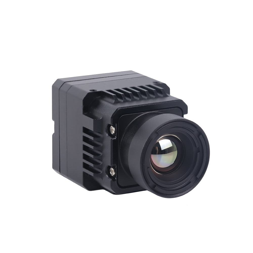
Mini 640×512 ASIC RJ45/CVBS Thermal Imaging Camera Module
الـ Mini 640×512 ASIC Thermal Sensor Camera Module integrates an uncooled 640×512 VOx microbolometer array with an advanced image processing ASIC engine. Built for tethered drones, PTZ surveillance systems, and multi-sensor electro-optical turrets, this module provides dual simultaneous outputs: compressed digital IP video over RJ45 Ethernet (supporting H.264/H.265 RTSP and ONVIF Profile S) alongside a real-time analog CVBS composite feed for zero-latency pilot viewing. Its onboard ASIC handles Non-Uniformity Correction (NUC), Digital Detail Enhancement (DDE), and pseudo-color palette generation directly on the hardware.
| نواة المستشعر: | 640 × 512 VOx High-Resolution Microbolometer |
| حجم البكسل: | 12 ميكرومتر |
| الحساسية الحرارية (NETD): | ≤ 40 mK |
| Integrated ISP: | Hardware ASIC with DDE, 3D Noise Reduction, AGC |
| Network Connectivity: | RJ45 10/100M Auto-Negotiating Ethernet |
| Network Protocols: | RTSP, ONVIF Profile S, TCP/IP, UDP, DHCP |
| Video Compression: | H.265 / H.264 Hardware Encoding |
| Analog Output: | 1-Channel CVBS (PAL / NTSC Standard Composite) |
Architectural Trade-Off Analysis
When choosing between these two module architectures, engineering teams must evaluate where video processing should occur within their overall system design:
- ✅ Choose the MIPI CSI-2 Module: Optimal when an onboard companion computer (such as an NVIDIA Jetson Orin, Raspberry Pi CM5, or Rockchip RK3588) resides within centimeters of the sensor core. Bypassing onboard H.264 compression ASICs minimizes overall power consumption, avoids video compression artifacts, preserves raw 14-bit radiometric depth, and eliminates transport latency. This makes it the preferred configuration for closed-loop drone tracking systems, autonomous collision avoidance, and precision industrial thermography.
- ✅ Choose the RJ45 / CVBS ASIC Module: Optimal when the sensor must operate independently or transmit over extended distances. The integrated ASIC handles video compression and network encapsulation onboard, allowing the module to stream directly over Ethernet cables, slip-rings, or wireless bridge modems without requiring an external companion computer. This architecture is best suited for security perimeter pan-tilt heads, tethered observation drones, and dual EO/IR surveillance pods.
فيديو مباشر للتصوير الحراري
الأسئلة الشائعة (تعمق)
What is the operational difference between an IR night-vision camera and a true uncooled thermal infrared camera module?
In contrast, a true uncooled thermal infrared camera module operates in the Long-Wave Infrared spectrum (LWIR: 8 to 14 μm) using a specialized microbolometer sensor (typically Vanadium Oxide). It does not detect reflected light; instead, it measures passive thermal radiation emitted directly by any object with a temperature above absolute zero (-273.15°C), in accordance with Planck's Radiation Law and the Stefan-Boltzmann Law. Thermal modules operate in complete darkness without requiring active light sources, penetrate environmental obscurants such as smoke, fog, and light foliage, and provide per-pixel radiometric temperature measurements.
How do I interface an OEM thermal camera module with companion computers like Raspberry Pi, NVIDIA Jetson, or PX4 flight controllers?
MIPI CSI-2 Integration (NVIDIA Jetson / Raspberry Pi CM4/CM5): Connect the module's flexible flat cable (FFC) to the carrier board's MIPI CSI-2 connector. The host operating system requires a custom Linux Device Tree Source (.dts) overlay and a Video4Linux2 (V4L2) kernel sub-device driver. This configuration establishes I2C communication for camera control registers and sets up the MIPI CSI-2 receiver to capture 14-bit linear data (typically configured as RAW14 or Y16) via Direct Memory Access (DMA). This pipeline delivers uncompressed frames straight into host RAM with minimal CPU overhead, enabling real-time processing through OpenCV, CUDA, or TensorRT pipelines.
RJ45 IP Integration: Connect the camera module to an onboard Ethernet switch or companion processor using a standard Cat5e/Cat6 cable. The integrated ASIC encodes the video stream into H.264/H.265 format. The host application accesses the feed using a GStreamer pipeline or OpenCV VideoCapture via RTSP (e.g., rtsp://192.168.1.100:554/live). This approach simplifies physical wiring across gimbal slip-rings, though it adds 80 to 180 ms of network buffering latency.
Flight Controller Integration (PX4 / ArduPilot): Thermal cores rarely connect directly to the main flight controller because microcontrollers lack the processing power needed to handle high-bandwidth video streams. Instead, wire the thermal module into an onboard companion computer. The companion processor runs target detection or temperature thresholding algorithms, then communicates with the flight controller over a UART or CAN interface using the standard MAVLink protocol. It can trigger alarms via STATUSTEXT messages or transmit target coordinates using LANDING_TARGET أو VISION_POSITION_ESTIMATE commands. If low-latency video is required for manual piloting, the module's CVBS analog output can route directly to an onboard 5.8 GHz analog video transmitter (VTX).
Why should commercial and defense UAV payloads upgrade from 256×192 or 384×288 sensors to a 640×512 resolution module?
With a 256×192 sensor, a human target located 300 meters away covers less than 2 pixels on the array. This limited coverage makes the target appear as an indistinct thermal blob, which leads to high false-positive rates and missed detections in edge AI models.
A 640×512 sensor resolves that same 300-meter target across more than 12 pixels. This provides sufficient structural detail for computer vision models (such as YOLOv8 or RT-DETR) to reliably extract distinctive features—such as head-and-shoulder geometry—dramatically reducing false alarms. Additionally, the higher pixel count allows the drone to operate at safer, higher flight altitudes while maintaining ground sampling resolution, or to scan significantly wider ground swaths per flight hour during search-and-rescue, wildlife surveys, or pipeline inspections.
How do optical materials and lens coatings affect thermal imaging performance?
الجرمانيوم أحادي البلورة (Ge): Germanium offers a high refractive index (~4.0) and very low optical dispersion, making it the industry standard for high-performance thermal lenses. However, it is dense, costly, and subject to thermal runaway—at temperatures exceeding 60°C to 70°C, its absorption increases rapidly, significantly reducing optical transmission.
زجاج الكالكوجينيد: An engineered amorphous material composed of selenium, sulfur, and tellurium. Chalcogenide glass is lighter and more cost-effective to produce than Germanium because it can be molded into precision aspheric lenses using hot glass pressing techniques. It also maintains optical transmission across wider temperature swings. Many modern drone lenses use hybrid optical designs, pairing a front Germanium element with internal Chalcogenide lenses to provide passive athermalization from -40°C to +80°C.
Optical Coatings: Lenses require Anti-Reflective (AR) coatings to overcome high Fresnel reflection losses (which can exceed 36% per surface on uncoated Germanium). Exterior lens elements also require Diamond-Like Carbon (DLC) hard coatings to protect against sand, rain erosion, and chemical corrosion during aerial missions.
What is the advantage of shutterless non-uniformity correction over traditional mechanical shutters in autonomous drone operations?
Eliminating Frame Drops: During calibration, the video output freezes. If the drone is executing high-speed autonomous flight, automated obstacle avoidance maneuvers, or tracking moving targets with visual servoing, this 500 ms blind spot can cause the tracking filter to lose its lock or interrupt flight navigation pipelines.
Mechanical Reliability: Solenoids and mechanical shutter blades are sensitive to sustained high-frequency motor vibrations from drone airframes. The mechanical assembly is often one of the first components to suffer mechanical wear or failure in harsh, high-vibration operational environments.
تحسين SWaP-C: Shutterless modules replace physical shutter mechanisms with factory-calibrated parametric algorithms. These algorithms monitor internal temperature sensors embedded across the sensor package and continuously apply correction matrices in software. This design eliminates mechanical moving parts, reduces total payload weight, lowers power consumption, and provides an uninterrupted video stream essential for autonomous navigation and AI-driven target tracking.
📚 المراجع والقراءات الإضافية
- المعيار الصناعي: Microbolometer manufacturing and thermal sensor production technologies by كويانغ and specialized semiconductor fabrication processes by جي إم شيب.
- دليل ذو صلة: Explore our comprehensive analysis on How to Choose the Best Infrared Thermal Imaging Camera Module for Drones & Embedded Systems.
- Embedded Integration: Read our technical guide on integrating MIPI CSI-2 thermal modules with Raspberry Pi and embedded platforms.
- System Categorization: Browse our library of electro-optical sensor modules in the thermal imaging engineering directory.