Best LWIR Camera Module for Embedded & UAV Systems: 2024 OEM Integration Guide
2026年10月13日
MIPI Thermal Camera Module: High-Res Embedded LWIR Cores for Drones & Edge AI
2026年10月14日
How to Choose the Best Infrared Camera Module: OEM Integration Guide for Drones & Embedded AI
Selecting an infrared camera module for commercial unmanned aerial vehicles (UAVs), tactical micro-gimbals, and edge-based artificial intelligence systems requires moving past conventional visual-spectrum imaging principles. Standard CMOS and CCD image sensors function across the visible spectrum (380 to 740 nm) or the near-infrared band (NIR: 750 to 1000 nm), mapping reflected photonic flux. In contrast, an uncooled long-wave infrared (LWIR) core measures passive electromagnetic radiation radiated directly by matter across the 8 to 14 μm thermal spectral window. For electro-optical payload engineers, robotics architects, and embedded software developers, choosing the right module involves balancing strict size, weight, power, and cost (SWaP-C) limitations against noise-equivalent thermal sensitivity (NETD), spatial sampling bounds, frame synchronization, optical transfer efficiency, and real-time transport bus latencies.
Modern autonomous inspection, search-and-rescue (SAR), tactical defense, automated perimeter surveillance, and industrial robotics demand instantaneous telemetry and feature extraction at the physical edge. Integrating a miniature thermal imaging core into carrier boards driven by platforms like the NVIDIA Jetson Orin series, Raspberry Pi Compute Module 4/5, or drone flight controllers executing PX4/ArduPilot autopilots presents complex integration trade-offs: balancing high-throughput raw pixel streams over MIPI CSI-2 against compressed RTSP transport over IP, mitigating non-uniformity correction (NUC) frame interruptions, and preserving true 14-bit linear radiometric depth for downstream convolutional neural network (CNN) inference. This integration guide walks through the physical principles, bus protocols, optical engineering factors, and software architectures necessary to deploy an OEM thermal imaging core successfully.
Table of Contents
- 👉 1. Understanding LWIR Microbolometer Architecture
- 👉 2. Electrical Interfaces: MIPI CSI-2 vs. USB vs. RJ45 vs. CVBS
- 👉 3. Resolution, Pixel Pitch, and DRI Range Calculations
- 👉 4. Edge AI & Radiometric Pipeline Integration
- 👉 5. OEM Product Specifications & Comparison
- 👉 6. Frequently Asked Questions (Deep-Dive)
1. Understanding LWIR Microbolometer Architecture
At the center of every uncooled thermal infrared camera module is the uncooled microbolometer focal plane array (FPA). Unlike cryogenically cooled mid-wave infrared (MWIR) or long-wave systems that require Stirling-cycle mechanical coolers operating at liquid nitrogen temperatures (~77 Kelvin), uncooled LWIR cores run at ambient structural temperatures. This structural simplicity slashes system mass, eliminates high acoustic signatures, drops operating power draw from tens of watts to under two watts, and extends mean time between failures (MTBF) past 15,000 continuous hours—making them practical for weight-constrained aerial drones and edge robotics.
The signal acquisition chain begins when thermal flux between 8 and 14 μm passes through an anti-reflective coated Germanium or Chalcogenide glass objective. The collected optical energy focuses onto a micro-machined, suspended bridge pixel structure positioned in an evacuated micro-cavity. This membrane absorbs incoming thermal flux, warming slightly and altering the material's bulk electrical resistance. Directly below each pixel, an integrated silicon Readout Integrated Circuit (ROIC) supplies an ultra-stable electrical bias and measures subtle resistance shifts across the array. An internal multi-channel Analog-to-Digital Converter (ADC) then digitizes these resistance shifts into a 14-bit or 16-bit linear digital representation of the thermal scene, feeding the uncalibrated data directly into an onboard FPGA or ASIC for processing.

Engineering a dependable thermal imaging core requires careful optimization across detector material science, sensor sensitivity tolerances, and calibration algorithms:
Material Physics: Vanadium Oxide (VOx) vs. Amorphous Silicon (a-Si)
The detector array consists of microscopic bridges suspended above a CMOS readout wafer by thin metal anchor legs. These legs isolate the detector, forming a vacuum cavity that prevents parasitic heat loss via air conduction. Each pixel absorbs thermal radiation, driving micro-Kelvin temperature shifts that modulate internal resistance based on the film's chemical and material composition:
- ✅ Vanadium Oxide (VOx): VOx remains the gold standard for high-performance defense and industrial thermal payloads. It features a high Temperature Coefficient of Resistance (TCR) ranging from -2%/K to -3%/K, delivering a high signal-to-noise ratio (SNR), low 1/f flicker noise, and consistent radiometric behavior across operating temperatures from -40°C to +85°C. In addition, VOx exhibits an agile thermal time constant (typically 8 to 12 ms), which minimizes frame ghosting and motion smearing during rapid drone yaw, roll, and pitch maneuvers.
- ⚙️ Amorphous Silicon (α-Si): While simpler to fabricate on standard CMOS production lines—lowering raw wafer manufacturing costs—α-Si features higher intrinsic 1/f noise, a lower TCR, and sluggish thermal response times (often 12 to 18 ms). This higher thermal latency makes α-Si sensors prone to edge smearing during rapid camera movement and reduces sensitivity in scenes with low thermal contrast, such as overcast fields or marine environments.
Advanced foundries such as JM Chip leverage ultra-thin VOx deposition techniques to build 12 μm pixel architectures that maintain thermal stability across broad ambient ranges without requiring bulky Peltier thermal stabilization hardware.
Noise Equivalent Temperature Difference (NETD)
Noise Equivalent Temperature Difference (NETD) serves as the primary metric for a thermal sensor's thermal sensitivity, quantified in millikelvins (mK). NETD represents the temperature differential between a target and its ambient background that yields a signal-to-noise ratio of exactly one. The physical relationship governing NETD is defined as:
NETD = (4 · F² · √(Δf)) / (π · Ad · τo · ε · (dP/dT) · D*)
Where F represents the lens optical f-number (typically F/1.0 to F/1.2 for LWIR setups), Δf is the electrical noise equivalent bandwidth, Ad is the physical pixel area, τo is the total optical transmission factor, dP/dT is the temperature derivative of the Planck blackbody radiant emittance, and D* is the normalized specific detectivity of the microbolometer film.
A module rated at NETD ≤ 40 mK (at F/1.0, 25°C) reliably resolves target differences down to 0.04°C. This resolving power is crucial when diagnosing moisture ingress behind composite aircraft skins, detecting hairline shorts or cracked bypass diodes in solar panels, tracking camouflaged human targets through forest canopy cover, or isolating fugitive hydrocarbon emissions. Conversely, budget sensors with poor sensitivity (NETD ≥ 60 to 80 mK) exhibit visible temporal grain and spatial noise, which degrades edge detection filters and undermines automated inference in edge vision pipelines.
Non-Uniformity Correction (NUC) and Shuttering Topologies
Because micro-scale lithography yields small variances in resistance, thermal capacitance, and amplifier gain across individual pixels, every thermal focal plane array requires dynamic offset and gain calibration through Non-Uniformity Correction (NUC):
- ⚙️ Mechanical Shutter NUC: A solenoid-driven mechanical blade drops across the optical axis directly in front of the FPA for 200 to 500 ms. The core samples an isothermal reference frame, calculates per-pixel baseline offsets, and updates onboard calibration registers. While this physical reference resets the baseline accurately, it freezes live video output during the cycle. This intermittent drop can disrupt visual odometry, cause drone flight controllers to lose target locks, or break automated tracking loops on moving subjects.
- ✅ Shutterless Algorithmic NUC: Industrial manufacturers such as KUYANG implement shutterless correction, combining multi-point factory calibration look-up tables (LUTs) with dynamic thermal drift modeling. Embedded firmware continuously samples onboard thermistors across the housing and adjusts spatial correction matrices mathematically in real time. This shutterless approach cuts structural mass, eliminates mechanical failure points, and ensures zero video interruption during mission-critical autonomous flight.
2. Electrical Interfaces: MIPI CSI-2 vs. USB vs. RJ45 vs. CVBS
Choosing the electrical and physical data bus governs overall system latency, host CPU overhead, cable harness routing through gimbal axes, and compatibility with edge compute architectures. OEM thermal cores offer distinct interface options, each matched to specific hardware stacks and data paths.
MIPI CSI-2 (Camera Serial Interface)
For embedded computers like the NVIDIA Jetson series (Orin Nano, Orin NX, AGX Orin), Raspberry Pi Compute Module 4 and 5, or dedicated Qualcomm robotics boards, MIPI CSI-2 represents the highest-efficiency integration bus. The thermal sensor connects directly via differential clock and data lanes into the host System on Chip (SoC) Image Signal Processor (ISP):
- ✅ Low Latency and High Throughput: Running over 2 or 4 differential data lanes based on the MIPI D-PHY standard, CSI-2 supports transfer rates from 1.5 to 2.5 Gbps per lane. Frames transfer straight into system DRAM via Direct Memory Access (DMA) without protocol handshakes or frame-level buffering, keeping end-to-end transport latency under 5 ms.
- ✅ Direct Radiometric Depth: Raw 14-bit or 16-bit linear digital data transfers cleanly across virtual channels as RAW14 or Y16 datatypes. This ensures edge inference routines receive unaltered per-pixel thermal signatures rather than lossy, 8-bit tone-mapped imagery.
- ⚙️ Hardware Engineering Challenges: Integrating via MIPI CSI-2 demands building custom Linux Video4Linux2 (V4L2) kernel drivers, compiling Device Tree Source (.dts) overlays for I2C register configuration, and routing tightly matched 100-ohm differential traces through compact carrier PCBs.
USB 2.0 / USB 3.0 (UVC Compliant)
USB interfaces remain the practical standard for prototyping, laboratory automation, and x86_64 industrial box PCs:
- ✅ Driver-Free Setup: UVC-compliant USB modules operate out-of-the-box across Linux, Windows, and ROS/ROS2 environments without requiring kernel rebuilds or custom device trees.
- ⚙️ Transport Latencies: Host controller scheduling, USB packet encapsulation, and driver queuing introduce 15 to 35 ms of transport latency. In addition, moving full 14-bit radiometric frames over UVC often requires splitting streams into bulk transfer endpoints or parsing custom metadata structures using vendor C++ or Python SDKs.
RJ45 Ethernet (IP RTSP / ONVIF Profile S)
Network-attached thermal cores serve as standard solutions for tethered inspection drones, security mast arrays, tactical perimeter mounts, and industrial facility monitoring:
- ✅ Integrated Encoding: An integrated hardware ASIC converts the raw sensor data into H.264 or H.265 compressed video on the fly, streaming it via Real-Time Streaming Protocol (RTSP) and ONVIF Profile S over standard 10/100/1000 Mbps Ethernet.
- ✅ Long Cable Runs: Cat5e and Cat6 twisted-pair wiring supports runs up to 100 meters without repeaters and passes cleanly through Ethernet-capable slip rings inside pan-tilt gimbal heads.
- ⚙️ Compression Latency: Encoding, IP packet assembly, routing, and decoding introduce a latency penalty of 80 to 200 ms. Furthermore, dynamic range compression down to standard 8-bit YUV/RGB color models discards true radiometric temperatures unless the module multiplexes a secondary KLV or UDP telemetry stream alongside the primary video feed.
CVBS (Composite Analog Video)
Composite Video Blanking and Sync (CVBS) provides an analog feed for legacy aerospace setups, handheld monitors, and low-latency First-Person View (FPV) drone piloting:
- ✅ Near-Zero Latency: CVBS outputs native PAL or NTSC signals through an unbalanced coaxial trace, delivering immediate video display without driver stacks, operating system layers, or compute overhead.
- ⚙️ Analog Restrictions: Resolution remains restricted to legacy 720×576 (PAL) or 720×480 (NTSC), the feed is susceptible to motor and RF interference on compact drone airframes, and it cannot carry digital radiometric telemetry.
| Interface Bus | Transport Latency | Radiometric Depth | Host CPU Utilization | Ideal Architecture |
|---|---|---|---|---|
| MIPI CSI-2 | < 5 ms (Glass-to-Memory) | Native 14-bit / 16-bit Raw | Near-Zero (Hardware DMA) | NVIDIA Jetson, Edge AI Robotics, UAV Autopilots |
| USB 2.0 / 3.0 | 15 – 35 ms | Raw14 or Compressed 8-bit | Moderate (USB Stack Parsing) | Industrial PC, Rapid Prototyping, Lab Automation |
| RJ45 Ethernet | 80 – 200 ms | 8-bit Video (Metadata via UDP) | Low (H.264 Hardware Decode) | Fixed PTZ, Tethered Drone Systems, Perimeter IP Video |
| CVBS Analog | < 1 ms | None (NTSC/PAL 8-bit Dynamic) | Zero (Direct Video Feed) | 5.8GHz FPV Drones, Backup Cockpit Displays |
For developers designing single-board computers into micro-drones or autonomous rovers, our technical walkthrough covers integrating MIPI thermal camera modules with Raspberry Pi and companion processors.
3. Resolution, Pixel Pitch, and DRI Range Calculations
A thermal payload's target acquisition envelope depends on sensor array resolution, pixel pitch, and lens focal length. System engineers quantify this performance using the established Johnson Criteria. Developed for electro-optical payload validation, these criteria outline the number of resolvable line pairs (or equivalent pixel cycles) required across an object's critical dimension to yield a 50% probability of successful Detection, Recognition, or Identification:
- ⚙️ Detection (1.5 line pairs / 3 pixels on target): The operator or automated edge pipeline observes a distinct thermal anomaly that stands out against ambient clutter.
- ⚙️ Recognition (6.0 line pairs / 12 pixels on target): The system differentiates the object's general class (e.g., distinguishing a person from an animal, or a tractor from an armored personnel carrier).
- ⚙️ Identification (12.0 line pairs / 24 pixels on target): The observer resolves fine structural features (e.g., identifying whether an individual is carrying equipment, or distinguishing specific vehicle variants).
The mathematical equation determining theoretical operational range (R) relative to target dimensions is expressed as:
Range (R) = (f · Dc) / (p · Npixels)
Where f denotes the optical focal length of the objective lens (mm), Dc is the target critical dimension (standardized at 0.75 meters for a human profile and 2.3 meters for a tactical vehicle), p is the microbolometer pixel pitch (μm), and Npixels represents the required pixel count across that critical dimension to achieve the Johnson threshold.
Comparing 256×192, 384×288, and 640×512 Sensor Formats
Microbolometer fabrication has largely shifted away from legacy 17 μm and 25 μm processes to dense 12 μm architectures. This shrink yields practical engineering advantages: it reduces the focal length required to achieve an identical field of view (enabling smaller, lighter Germanium elements), and it shrinks the overall module footprint to fit inside compact, stabilized drone gimbals.
| Array Resolution | Total Active Pixels | Field of View (9mm Lens) | Human Detection (R) | Human Identification (R) |
|---|---|---|---|---|
| 256 × 192 (12 μm) | 49,152 | 19.6° × 14.7° | ~187 meters | ~23 meters |
| 384 × 288 (12 μm) | 110,592 | 29.2° × 22.1° | ~281 meters | ~35 meters |
| 640 × 512 (12 μm) | 327,680 | 48.2° × 39.1° | ~562 meters | ~70 meters |
A 640×512 focal plane array delivers **6.66 times the spatial information** of an entry-level 256×192 sensor. For commercial drone missions, this higher resolution offers practical flight advantages: the aircraft can fly at higher, safer altitudes while maintaining the ground sampling distance (GSD) needed to detect targets, or it can cover a broader swath during each search pass over the operational area. For an in-depth breakdown of core selection criteria, consult our detailed thermal imaging camera module selection guide.
4. Edge AI & Radiometric Pipeline Integration
Processing infrared thermal frames on edge compute platforms introduces operational requirements that differ significantly from standard RGB pipelines. Visible-spectrum sensors output 8-bit per-channel RGB color values representing surface reflectance. In contrast, an uncooled microbolometer sensor outputs a single-channel, high-dynamic-range matrix of 14-bit unsigned integers (ranging from 0 to 16,383 digital counts) that directly correlate with scene radiance.
Ingesting 14-Bit Linear Arrays vs. 8-Bit Contrast Images
Thermal system architects must decide where to process dynamic range within the vision pipeline:
- ⚙️ 14-Bit Radiometric Linear Bus: This mode preserves raw digital sensor values across the entire scene. Downstream software applies factory calibration polynomials to convert each digital count into an absolute temperature reading using the Stefan-Boltzmann and Planck equations:
T = B / ln((R / (S - O)) + F)
Where S is the raw 14-bit pixel count, and R, B, F, O are factory-calibrated Planck constants stored inside the camera's non-volatile memory. Radiometric accuracy is vital for electrical grid predictive maintenance, industrial flare-stack monitoring, pipeline leak localization, and geothermal mapping. - ⚙️ 8-Bit Tone-Mapped Stream (AGC / Dynamic Range Compression): Compresses the wide 14-bit dynamic range down to an 8-bit window (0 to 255) using techniques such as Digital Detail Enhancement (DDE) or Contrast-Limited Adaptive Histogram Equalization (CLAHE). While this compression creates balanced visual imagery for human viewing on ground stations, it permanently discards absolute temperature data, making post-capture temperature measurements impossible.
Dual-Pipeline Edge Architecture
To support autonomous UAV tracking alongside high-precision thermal measurement, embedded systems often run two parallel processing paths from a single MIPI CSI-2 input:
- ⚙️ Path A: The Deep Learning Computer Vision Branch: The pipeline extracts the raw 14-bit input frame, applies bilateral spatial filtering to reduce high-frequency microbolometer fixed-pattern noise without softening thermal edges, and applies dynamic range equalization to normalize the scene. The output is converted into an 8-bit tensor (640×512×1) and routed into a TensorRT-optimized convolutional neural network or vision transformer (such as YOLOv8, YOLOv10, or RT-DETR). Because infrared targets lack surface color textures, edge AI models rely heavily on shape geometry, edge gradients, and thermal contrast. High sensor sensitivity (NETD ≤ 40 mK) is essential for maintaining high Intersection-over-Union (IoU) scores and preventing target loss.
- ⚙️ Path B: The Radiometric Telemetry & Alarming Branch: Operating alongside the vision branch, this path monitors the unaltered 14-bit linear data. When the computer vision model identifies an object (such as a utility power transformer or industrial storage tank), the system samples the raw pixel values within that bounding box. The processor calculates minimum, maximum, and average temperatures inside the region of interest. If a reading exceeds a preset safety threshold, the system packages the coordinates and temperature data into a MAVLink telemetry packet (e.g.,
CAMERA_FEEDBACKorSTATUSTEXT) and transmits an immediate alert to the drone flight controller or ground control station.
5. OEM Product Specifications & Comparison
For system integrators, embedded engineers, and drone gimbal manufacturers evaluating hardware for integration, the following two enterprise-grade infrared camera modules illustrate how interface choice and processing topology adapt to different application profiles.

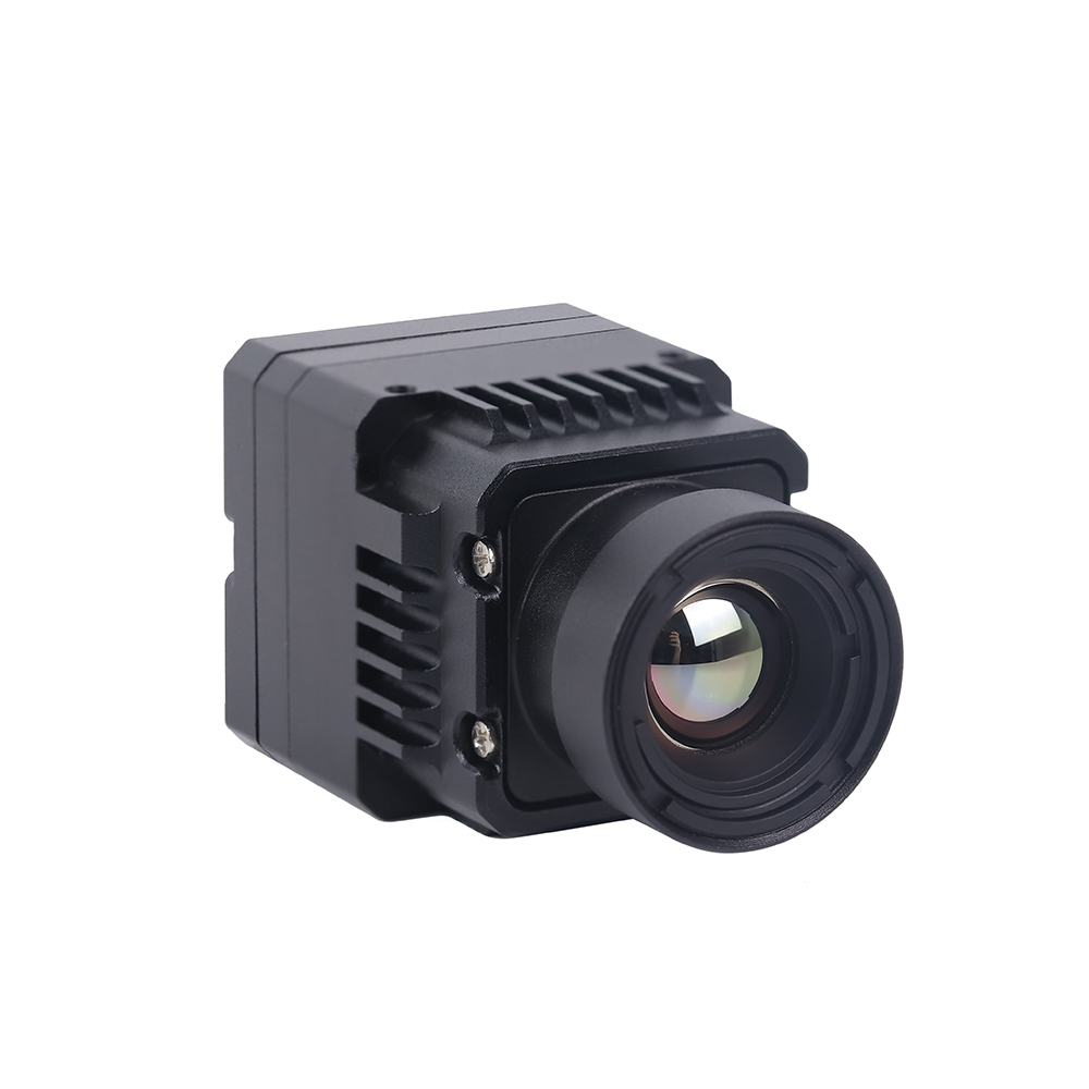
Mini2 640×512 9mm MIPI Thermal Imaging Camera Module
The Mini2 640×512 9mm MIPI Thermal Camera Module is an ultra-compact, lightweight, uncooled long-wave infrared core designed for commercial drone gimbals, edge computing platforms, and SWaP-C constrained embedded systems. Featuring a high-resolution 640×512 Vanadium Oxide (VOx) focal plane array with a 12 μm pixel pitch, it delivers sharp thermal imagery with exceptional dynamic sensitivity (NETD ≤ 40 mK). Its low-power architecture and native MIPI CSI-2 interface provide direct access to raw 14-bit radiometric data, enabling seamless integration with NVIDIA Jetson Orin and Raspberry Pi compute platforms with near-zero latency.
| Focal Plane Array: | 640 × 512 Uncooled VOx Microbolometer |
| Pixel Pitch: | 12 μm |
| Spectral Band: | 8 to 14 μm (LWIR) |
| Thermal Sensitivity (NETD): | ≤ 40 mK @ 25°C, F/1.0 |
| Optical Configuration: | 9mm Athermalized Chalcogenide/Germanium (F/1.0) |
| Output Data Interface: | MIPI CSI-2 (RAW14 / YUV422 selectable) |
| Frame Rate: | 25 Hz / 30 Hz / 50 Hz Configurable |
| Power Consumption: | < 1.2 Watts typical |
Mini 640×512 ASIC RJ45/CVBS Thermal Imaging Camera Module
The Mini 640×512 ASIC Thermal Sensor Camera Module integrates an uncooled 640×512 VOx microbolometer array with an advanced image processing ASIC engine. Built for tethered drones, PTZ surveillance systems, and multi-sensor electro-optical turrets, this module provides dual simultaneous outputs: compressed digital IP video over RJ45 Ethernet (supporting H.264/H.265 RTSP and ONVIF Profile S) alongside a real-time analog CVBS composite feed for zero-latency pilot viewing. Its onboard ASIC handles Non-Uniformity Correction (NUC), Digital Detail Enhancement (DDE), and pseudo-color palette generation directly on the hardware.
| Sensor Core: | 640 × 512 VOx High-Resolution Microbolometer |
| Pixel Pitch: | 12 μm |
| Thermal Sensitivity (NETD): | ≤ 40 mK |
| Integrated ISP: | Hardware ASIC with DDE, 3D Noise Reduction, AGC |
| Network Connectivity: | RJ45 10/100M Auto-Negotiating Ethernet |
| Network Protocols: | RTSP, ONVIF Profile S, TCP/IP, UDP, DHCP |
| Video Compression: | H.265 / H.264 Hardware Encoding |
| Analog Output: | 1-Channel CVBS (PAL / NTSC Standard Composite) |
Architectural Trade-Off Analysis
When choosing between these two module architectures, engineering teams must evaluate where video processing should occur within their overall system design:
- ✅ Choose the MIPI CSI-2 Module: Optimal when an onboard companion computer (such as an NVIDIA Jetson Orin, Raspberry Pi CM5, or Rockchip RK3588) resides within centimeters of the sensor core. Bypassing onboard H.264 compression ASICs minimizes overall power consumption, avoids video compression artifacts, preserves raw 14-bit radiometric depth, and eliminates transport latency. This makes it the preferred configuration for closed-loop drone tracking systems, autonomous collision avoidance, and precision industrial thermography.
- ✅ Choose the RJ45 / CVBS ASIC Module: Optimal when the sensor must operate independently or transmit over extended distances. The integrated ASIC handles video compression and network encapsulation onboard, allowing the module to stream directly over Ethernet cables, slip-rings, or wireless bridge modems without requiring an external companion computer. This architecture is best suited for security perimeter pan-tilt heads, tethered observation drones, and dual EO/IR surveillance pods.
THERMAL IMAGING REAL-TIME VIDEO
6. Frequently Asked Questions (Deep-Dive)
What is the operational difference between an IR night-vision camera and a true uncooled thermal infrared camera module?
In contrast, a true uncooled thermal infrared camera module operates in the Long-Wave Infrared spectrum (LWIR: 8 to 14 μm) using a specialized microbolometer sensor (typically Vanadium Oxide). It does not detect reflected light; instead, it measures passive thermal radiation emitted directly by any object with a temperature above absolute zero (-273.15°C), in accordance with Planck's Radiation Law and the Stefan-Boltzmann Law. Thermal modules operate in complete darkness without requiring active light sources, penetrate environmental obscurants such as smoke, fog, and light foliage, and provide per-pixel radiometric temperature measurements.
How do I interface an OEM thermal camera module with companion computers like Raspberry Pi, NVIDIA Jetson, or PX4 flight controllers?
MIPI CSI-2 Integration (NVIDIA Jetson / Raspberry Pi CM4/CM5): Connect the module's flexible flat cable (FFC) to the carrier board's MIPI CSI-2 connector. The host operating system requires a custom Linux Device Tree Source (.dts) overlay and a Video4Linux2 (V4L2) kernel sub-device driver. This configuration establishes I2C communication for camera control registers and sets up the MIPI CSI-2 receiver to capture 14-bit linear data (typically configured as RAW14 or Y16) via Direct Memory Access (DMA). This pipeline delivers uncompressed frames straight into host RAM with minimal CPU overhead, enabling real-time processing through OpenCV, CUDA, or TensorRT pipelines.
RJ45 IP Integration: Connect the camera module to an onboard Ethernet switch or companion processor using a standard Cat5e/Cat6 cable. The integrated ASIC encodes the video stream into H.264/H.265 format. The host application accesses the feed using a GStreamer pipeline or OpenCV VideoCapture via RTSP (e.g., rtsp://192.168.1.100:554/live). This approach simplifies physical wiring across gimbal slip-rings, though it adds 80 to 180 ms of network buffering latency.
Flight Controller Integration (PX4 / ArduPilot): Thermal cores rarely connect directly to the main flight controller because microcontrollers lack the processing power needed to handle high-bandwidth video streams. Instead, wire the thermal module into an onboard companion computer. The companion processor runs target detection or temperature thresholding algorithms, then communicates with the flight controller over a UART or CAN interface using the standard MAVLink protocol. It can trigger alarms via STATUSTEXT messages or transmit target coordinates using LANDING_TARGET or VISION_POSITION_ESTIMATE commands. If low-latency video is required for manual piloting, the module's CVBS analog output can route directly to an onboard 5.8 GHz analog video transmitter (VTX).
Why should commercial and defense UAV payloads upgrade from 256×192 or 384×288 sensors to a 640×512 resolution module?
With a 256×192 sensor, a human target located 300 meters away covers less than 2 pixels on the array. This limited coverage makes the target appear as an indistinct thermal blob, which leads to high false-positive rates and missed detections in edge AI models.
A 640×512 sensor resolves that same 300-meter target across more than 12 pixels. This provides sufficient structural detail for computer vision models (such as YOLOv8 or RT-DETR) to reliably extract distinctive features—such as head-and-shoulder geometry—dramatically reducing false alarms. Additionally, the higher pixel count allows the drone to operate at safer, higher flight altitudes while maintaining ground sampling resolution, or to scan significantly wider ground swaths per flight hour during search-and-rescue, wildlife surveys, or pipeline inspections.
How do optical materials and lens coatings affect thermal imaging performance?
Monocrystalline Germanium (Ge): Germanium offers a high refractive index (~4.0) and very low optical dispersion, making it the industry standard for high-performance thermal lenses. However, it is dense, costly, and subject to thermal runaway—at temperatures exceeding 60°C to 70°C, its absorption increases rapidly, significantly reducing optical transmission.
Chalcogenide Glass: An engineered amorphous material composed of selenium, sulfur, and tellurium. Chalcogenide glass is lighter and more cost-effective to produce than Germanium because it can be molded into precision aspheric lenses using hot glass pressing techniques. It also maintains optical transmission across wider temperature swings. Many modern drone lenses use hybrid optical designs, pairing a front Germanium element with internal Chalcogenide lenses to provide passive athermalization from -40°C to +80°C.
Optical Coatings: Lenses require Anti-Reflective (AR) coatings to overcome high Fresnel reflection losses (which can exceed 36% per surface on uncoated Germanium). Exterior lens elements also require Diamond-Like Carbon (DLC) hard coatings to protect against sand, rain erosion, and chemical corrosion during aerial missions.
What is the advantage of shutterless non-uniformity correction over traditional mechanical shutters in autonomous drone operations?
Eliminating Frame Drops: During calibration, the video output freezes. If the drone is executing high-speed autonomous flight, automated obstacle avoidance maneuvers, or tracking moving targets with visual servoing, this 500 ms blind spot can cause the tracking filter to lose its lock or interrupt flight navigation pipelines.
Mechanical Reliability: Solenoids and mechanical shutter blades are sensitive to sustained high-frequency motor vibrations from drone airframes. The mechanical assembly is often one of the first components to suffer mechanical wear or failure in harsh, high-vibration operational environments.
SWaP-C Optimization: Shutterless modules replace physical shutter mechanisms with factory-calibrated parametric algorithms. These algorithms monitor internal temperature sensors embedded across the sensor package and continuously apply correction matrices in software. This design eliminates mechanical moving parts, reduces total payload weight, lowers power consumption, and provides an uninterrupted video stream essential for autonomous navigation and AI-driven target tracking.
📚 References & Further Reading
- Industry Standard: Microbolometer manufacturing and thermal sensor production technologies by KUYANG and specialized semiconductor fabrication processes by JM Chip.
- Related Guide: Explore our comprehensive analysis on How to Choose the Best Infrared Thermal Imaging Camera Module for Drones & Embedded Systems.
- Embedded Integration: Read our technical guide on integrating MIPI CSI-2 thermal modules with Raspberry Pi and embedded platforms.
- System Categorization: Browse our library of electro-optical sensor modules in the thermal imaging engineering directory.