أفضل وحدة كاميرا حرارية لتكامل الطائرات بدون طيار: دليل لمصنعي المعدات الأصلية B2B
٢ يوليو ٢٠٢٦
وحدة كاميرا حرارية 640 512 35 مم: دليل التكامل النهائي B2B للطائرات بدون طيار و Edge AI
٣ يوليو ٢٠٢٦
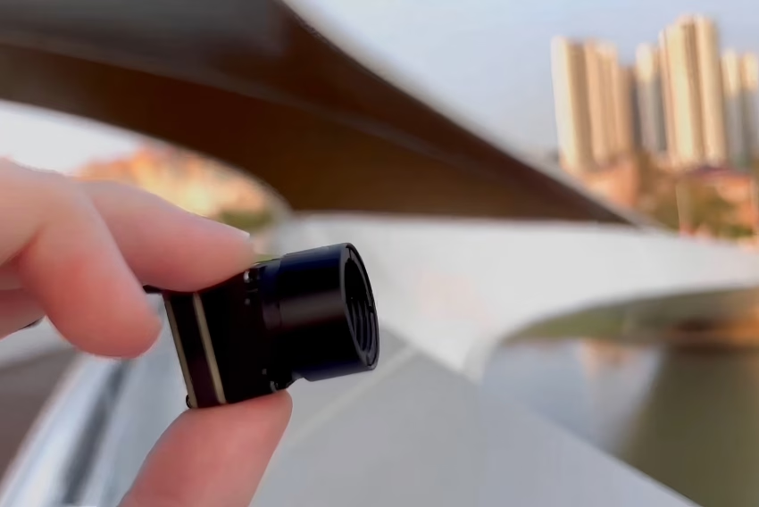
كيفية اختيار أفضل وحدة كاميرا تصوير حراري بالأشعة تحت الحمراء للطائرات بدون طيار، Raspberry Pi، وتكامل Edge AI
الملخص التنفيذي والمبادئ المعمارية على مستوى النظام
لقد انتقل تطور تقنية مستشعرات الأشعة تحت الحمراء طويلة الموجة (LWIR) غير المبردة من التجميعات العسكرية الثقيلة والمستهلكة للطاقة إلى وحدات فائقة الصغر وعالية الدقة وحدات كاميرات التصوير الحراري بالأشعة تحت الحمراء المصممة للدمج في المركبات الجوية غير المأهولة (UAVs)، والحواسيب أحادية اللوحة (SBCs)، ومحركات الذكاء الاصطناعي الطرفية. بالنسبة لمهندسي الإلكترونيات، ومكاملي الأنظمة، ومهندسي البرمجيات، فإن اختيار نواة التصوير الحراري الصحيحة ليس مجرد مسألة اختيار دقة. إنه يتطلب موازنة عميقة بين ميزانيات الوزن، والواجهات الكهربائية، وبروتوكولات البيانات، والحساسية الحرارية (NETD).
للتنقل في هذا المشهد، يحلل دليل النشر هذا المتطلبات الفيزيائية والكهربائية والحسابية لدمج وحدات LWIR عالية الأداء. من خلال مقارنة الواجهات الخام مثل MIPI CSI-2 مع التدفقات المغلفة بالشبكة مثل RJ45 RTSP/IP، يقدم هذا الدليل المعايير الدقيقة اللازمة لنشر مصفوفات الميكروبولومتر غير المبردة في بيئات معقدة متعددة المستشعرات.
من خلال التقييم المنهجي للخصائص البصرية، وخطوط الأنابيب العتادية، وواجهات البرمجيات، والقيود الفيزيائية، يمكن لفرق تطوير الأنظمة تحسين تصاميم الاستشعار الحراري الخاصة بهم. تحدد هذه الوثيقة المبادئ الفيزيائية وراء اكتساب إشارة الأشعة تحت الحمراء طويلة الموجة الخام، وتفصل الاختلافات الأساسية بين معالجة السجلات المباشرة وتكوينات البث الشبكي، وتوفر إرشادات خطوة بخطوة لتحقيق عمليات الدمج العتادية.
جدول المحتويات
- 👉 الأساسيات الفيزيائية والبصرية لوحدات LWIR الحرارية
- 👉 الواجهات الكهربائية وبروتوكولات الفيديو: MIPI CSI-2 مقابل RTSP/IP
- 👉 عروض المنتجات التفصيلية: المواصفات الفنية وأوراق البيانات
- 👉 دليل الدمج خطوة بخطوة مع Raspberry Pi
- 👉 نشر الذكاء الاصطناعي الطرفي الصناعي ونواة دمج المستشعرات المتعددة
- 👉 الأسئلة الشائعة المتعمقة (FAQ)
الأساسيات الفيزيائية والبصرية لوحدات LWIR الحرارية
يتطلب تطوير نظام تصوير حراري من الدرجة الصناعية فهمًا قويًا للفيزياء، وعلوم المواد، والهندسة البصرية. تعمل وحدات كاميرات التصوير الحراري غير المبردة في نطاق الأشعة تحت الحمراء طويلة الموجة (LWIR)، والذي يتراوح عادةً من 8 ميكرومتر إلى 14 ميكرومتر. على عكس كاميرات الضوء المرئي التي تعتمد على الفوتونات المنعكسة، تكتشف مستشعرات LWIR الإشعاع الحراري الذاتي المنبعث من الأجسام، والذي يتناسب طرديًا مع درجة حرارتها الديناميكية الحرارية المطلقة كما هو موصوف في قانون بلانك وقانون ستيفان-بولتزمان.
1 الدقة، وتباعد البكسلات، وتنسيق المستشعر
نواة الكاميرا الحرارية غير المبردة هي مصفوفة المستوى البؤري (FPA) للميكروبولومتر. تُصنع مصفوفات FPA الحديثة باستخدام مقاومات الأغشية الرقيقة من أكسيد الفاناديوم (VOx) أو السيليكون غير المتبلور (α-Si) المترسبة على دارة متكاملة لقراءة السيليكون (ROIC).
فيما يلي كيفية تبلور الخيارات المعمارية الرئيسية على اللوحة:
- ⚙️ الدقة: تشمل تكوينات التصوير الحراري القياسية مصفوفات بكسلات 192×256، و288×384، و512×640. تملي الدقة مباشرة التفاصيل المكانية للمشهد. تحتوي مصفوفة 512×640 على 327,680 كاشف ميكروبولومتر فردي، مما يوفر سياقًا مكانيًا خامًا مناسبًا للبحث والإنقاذ بالطائرات بدون طيار، وعمليات التفتيش الآلي للألواح الشمسية، وخطوط أنابيب اكتشاف الأجسام المعقدة للذكاء الاصطناعي الطرفي.
- ⚙️ حجم البكسل: يشير هذا إلى المسافة من المركز إلى المركز بين عناصر الكاشف المتجاورة على مصفوفة المستشعر، وتُقاس بالميكرومتر (μm). وقد انتقلت الصناعة من مصفوفات 17 ميكرومتر إلى 12 ميكرومتر. يسمح تقليل تباعد البكسل بتقليل حجم شريحة السيليكون، مما يخفض الوزن الإجمالي وتكلفة تصنيع المستشعر. ومع ذلك، فإن تباعد البكسل الأصغر يقلل أيضًا من مساحة الالتقاط النشطة لكل بكسل، مما يتطلب أداءً بصريًا أعلى (رقم بؤري أقل) وخوارزميات ربح مستشعر محدثة للحفاظ على حساسية حرارية عالية.
2 فهم المعلمات البصرية: البعد البؤري، ومجال الرؤية، والرقم البؤري
نظرًا لأن الزجاج يمتص طاقة الأشعة تحت الحمراء طويلة الموجة، تستخدم وحدات الأشعة تحت الحمراء غير المبردة عدسات متخصصة مصنوعة من الجرمانيوم أحادي البلورة (Ge) أو زجاج الكالكوجينيد، كاملة مع طلاءات مضادة للانعكاس (AR).
- ⚙️ البعد البؤري (f): يُقاس في مسافات البحث والنشر، ويتحكم البعد البؤري في كل من مجال الرؤية الزاوي (FOV) ومجال الرؤية اللحظي (IFOV). يمثل مجال الرؤية اللحظي الدقة المكانية لبكسل واحد على مسافة محددة (d):
IFOV = تباعد البكسل / fاستخدام عدسة 9 مم على مستشعر 12 ميكرومتر يعطي مجال رؤية لحظي قدره:
IFOV = (12 * 10^-6 م) / (9 * 10^-3 م) = 1.33 مللي راديانهذا يعني أنه على مسافة 100 متر، يحلل بكسل واحد مساحة 13.3 سم.
- ⚙️ مجال الرؤية (FOV): يُحسب باستخدام حجم المستشعر الفعلي (العرض × الارتفاع) والبعد البؤري للعدسة (f)، ويتم التعبير عن حسابات مجال الرؤية الأفقي (H_FOV) والرأسي (V_FOV) على النحو التالي:
θ = 2 * ظل الزاوية العكسي (W / (2 * f))شريحة بدقة 640×512 مع تباعد 12 ميكرومتر لها عرض مستشعر نشط يبلغ 7.68 مم (640 * 12 ميكرومتر). مقترنة بعدسة 9 مم، تحقق مجال رؤية أفقي واسع يبلغ حوالي 46.2°، مما يجعلها فعالة للغاية لرسم الخرائط بطائرات بدون طيار واسعة النطاق ومراقبة المرافق الجوية.
- ⚙️ الفتحة (الرقم البؤري): يُشار إليها بـ F/1.0 أو F/1.2 أو F/1.3، وهي نسبة البعد البؤري للعدسة إلى قطر بؤبؤ الدخول. نظرًا لأن الطاقة الحرارية المنبعثة من الأهداف المحيطة منخفضة، تتطلب الأنظمة البصرية للأشعة تحت الحمراء طويلة الموجة فتحات سريعة (عادةً F/1.0 إلى F/1.2) لتعظيم تجميع الفوتونات:
التدفق الحراري الواصل إلى FPA ∝ 1 / (F/#)^2توصل عدسة F/1.0 ضعف الطاقة الحرارية إلى مصفوفة المستشعر مقارنة بعدسة F/1.4، مما يحسن بشكل كبير جودة صورة الوحدة ونسبة الإشارة إلى الضوضاء الإجمالية.
3 الحساسية الحرارية (NETD) وملفات المعايرة
يحدد فرق درجة الحرارة المكافئ للضوضاء (NETD) الحد الأدنى لفرق درجة الحرارة الذي يمكن لمستشعر الميكروبولومتر غير المبرد تحليله. وهو يمثل حد الضوضاء للنظام، حيث تساوي نسبة الإشارة إلى الضوضاء واحدًا (S/N = 1)، ويُقاس بالميلي كلفن (mK).
- ⚙️ المعيار الصناعي: NETD أقل من 50 مللي كلفن (عند 25 درجة مئوية، F/1.0) هو المعيار الصناعي للوحدات عالية الأداء. تحقق المكونات المتطورة مثل النوى الحديثة غير المبردة حساسيات تبلغ ≤40 مللي كلفن. تترجم قيم NETD المنخفضة مباشرة إلى ملفات حرارية أنظف، وتقليل ضوضاء الملح والفلفل، وملفات مدى أفضل خلال ظروف التباين المنخفض (مثل الأيام الملبدة بالغيوم أو الممطرة).
- ⚙️ المعايرة (NUC): الميكروبولومترات للأشعة تحت الحمراء طويلة الموجة حساسة للغاية لدرجة حرارة جسم الكاميرا نفسه، والتي يمكن أن تنحرف وتتسبب في تغير أرباح كل بكسل على حدة بمرور الوقت. للحفاظ على صور صحيحة وخالية من الانحراف، تطبق الوحدات تصحيح عدم الانتظام (NUC). يتم ذلك باستخدام مصراع ميكانيكي داخلي (أو خوارزميات بدون مصراع للتطبيقات المخصصة) لإعادة معايرة FPA مقابل مصدر درجة حرارة منتظم.
- ⚙️ تنسيقات البيانات (8-بت مقابل 14-بت): بالنسبة للرؤية الآلية وقياس درجة الحرارة، ينتج النواة غير المبردة صيغتي بيانات أساسيتين:
- ✅ بيانات رقمية خام 14-بت (Y14): توفر خرجًا رقميًا مباشرًا يتناسب مع الإشعاع الخام أو درجة الحرارة المعايرة لكل بكسل. يُعد تدفق البيانات عالي العمق هذا ضروريًا للتطبيقات الإشعاعية، مما يسمح للمطورين بحساب درجات الحرارة المطلقة عبر نطاق ديناميكي واسع (مثل -20°C إلى +150°C أو +550°C).
- ✅ فيديو مضغوط 8-بت (YUV422 / Mono8 / RGB): يتم توليده بتمرير الإشارة الخام 14-بت عبر خوارزميات النطاق الديناميكي الآلية، مثل معادلة المدرج التكراري التكيفي المحدود التباين (CLAHE). صُمم هذا الخرج المضغوط للعرض المباشر والمراقبة البشرية.
الواجهات الكهربائية وبروتوكولات الفيديو: MIPI CSI-2 مقابل RTSP/IP
عند دمج وحدة كاميرا تصوير حراري بالأشعة تحت الحمراء في منصة مدمجة، يمثل اختيار الواجهة الكهربائية الفيزيائية خطوة معمارية رئيسية.
1 غوص عميق في MIPI CSI-2 (واجهة معالج الصناعة المتنقلة)
MIPI CSI-2 هي واجهة تسلسلية تفاضلية عالية السرعة من نقطة إلى نقطة، طُورت لأنظمة الكاميرات المتنقلة والمدمجة.
- ⚙️ الطبقة الفيزيائية: تعمل عبر الطبقة الفيزيائية MIPI D-PHY، مستخدمة مسار ساعة متزامن مع المصدر عالي السرعة ومسار بيانات تفاضلي واحد أو أكثر.
- ⚙️ Signal Routing and Integrity: MIPI differential trace lines must be precisely length-matched (within 0.1 mm mismatch tolerance) and kept away from high-frequency lines (such as switching power regulators or high-speed RAM pathways) to prevent electromagnetic interference. Imbalance in trace impedance (which should be maintained at 100 Ω differential ±10%) can degrade data packets, resulting in frame drops or synchronization issues in the video feed.
- ⚙️ Latency Analysis: MIPI CSI-2 bypasses local compression codecs, streaming raw video formats (such as RAW8, RAW10, RAW12, RAW14, or YUV422) directly into the Host processor's memory via Direct Memory Access (DMA). This provides minimal latency (typically <5 ms propagation delay), which is essential for closed-loop drone flight control adjustments, hazard evasion systems, and highly responsive camera gimbals.
- ⚙️ Driver Configuration: Interfacing a MIPI thermal module using Linux requires loading a matching driver into the kernel via a Device Tree Blob (DTB). This driver registers the thermal module with the Video4Linux2 (V4L2) sub-system, allowing developers to query camera features and change capture profiles via industry-standard ioctl calls.
2.2 RJ45 Ethernet, RTSP, and IP-Based Streaming Pipelines
For systems where the thermal sensor is installed far from the primary processing unit (such as on tall security towers, large industrial robotic arms, or expansive drone platforms), MIPI CSI-2 is limited by its short transmission range (typically <15 cm without dedicated active signal buffers). In these scenarios, RJ45 IP and RTSP configurations are the preferred approach.
- ⚙️ Ethernet Physical Layer: Uses standard 100Base-TX/1000Base-T physical layer transceiver circuits (PHYs) to transmit network data reliably over distances up to 100 meters using standard copper Twisted Pair (Cat5e/Cat6) cables.
- ⚙️ Onsite Compression Encoding: A dedicated onsite ASIC or System-on-Chip (SoC) sitting within the camera module captures raw sensor data, processes it, and compresses it using standard video standards like H.264 or H.265. This encoding step introduces a slight delay (typically 80 ms to 150 ms) depending on frame rate, keyframe intervals (GoP), and the performance of the encoder.
- ⚙️ Network Streaming Protocols:
- ✅ RTSP (Real-Time Streaming Protocol): Manages the video stream connection, supporting system control actions like play, pause, and teardown.
- ✅ RTP (Real-time Transport Protocol): Packages the H.264/H.265 compressed frames into individual UDP network packets, sending them to target clients in real time.
- ✅ RTCP (RTP Control Protocol): Monitors transmission quality, providing feedback on packet loss and jitter to help the video encoder dynamically adjust its bitrate.
- ⚙️ Integration with IoT and Security Software: Because the module acts as a standard network device, it integrates directly with standard Video Management Systems (VMS) like Milestone, Qognify, and open-source software like ZoneMinder, as well as developer libraries like OpenCV (
cv2.VideoCapture("rtsp://...")). This allows the camera to plug directly into pre-existing network infrastructure without needing specialized low-level device drivers.
2.3 Comparative Interface Matrix for Hardware Architects
| Metric / Parameter | واجهة MIPI CSI-2 | RJ45 Ethernet / RTSP / IP Interface |
|---|---|---|
| تنسيق البيانات | Raw Digital (Y14 14-bit / YUV422 8-bit) | Compressed Stream (H.264 / H.265) |
| Transmission Distance | <15 cm (requires short flat flex cables) | Up to 100 meters (utilizes standard network cabling) |
| System Latency | Direct DMA (<5 ms) | Compression/Decompression Delay (80 ms - 150 ms) |
| Host Resource Usage | High CPU overhead for raw pixel-to-temperature conversion | Low CPU overhead (decoded via GPU or hardware-accelerated blocks) |
| Cabling Weight/Factor | Micro-thin Flex Cable (ideal for lightweight gimbals) | Cat5e/Cat6 Shielded Cable (thicker and heavier) |
| Multi-Camera Routing | Requires dedicated hardware lanes on the CPU | Standard network routing via commercial Ethernet switches |
| Driver Integration | Low-level kernel driver & custom DTB compiled configuration | Universal network compatibility; streams via standard sockets |
For further technical system designs and advanced multi-protocol drone configurations, refer to the Purpleriver Drone Integration Thermal Blog.
عروض المنتجات التفصيلية: المواصفات الفنية وأوراق البيانات
Selecting an uncooled LWIR sensor core requires analyzing physical and electronic parameters from the manufacturer's data sheets. Below are two representative modules, showcasing the distinction between a raw, lightweight MIPI CSI-2 interface and an integrated RJ45 network-streaming core.
3.1 Purpleriver Mini2 640x512 9mm LWIR MIPI Module
الـ Purpleriver Mini2 640x512 9mm Uncooled Infrared MIPI Thermal Imaging Camera Module is engineered specifically for SWaP-constrained (Size, Weight, and Power) applications, such as lightweight multirotor UAV payloads and compact handheld devices.
Uncooled Infrared Mini2 640x512 9mm Thermal Imaging Camera Module For Drones features sharp and crisp image presentation, extremely compact size, and low cost. It outputs a 14-bit digital stream directly via a lightweight MIPI interface, removing unnecessary processing overhead. This allows for direct temperature measurements while keeping weight to an absolute minimum.
- ✅ Primary Applications: Lightweight drone payloads, thermal mapping, compact hand-held diagnostic systems, micro-UAV gimbals.
- ✅ Key Advantage: Extremely compact 21 mm × 21 mm physical footprint. Can be integrated directly into brush-less gimbals without affecting stabilization kinetics.
3.2 Purpleriver 640x512 ASIC RJ45 RTSP IP Thermal Module
الـ Purpleriver Uncooled Infrared RJ45 CVBS RTSP IP 640*512 ASIC Thermal Sensor Camera Module incorporates an onboard Application-Specific Integrated Circuit (ASIC) designed to process, compress, and stream thermal video directly over standard network infrastructure.
Here's the deal: with this module, you aren't wasting days cooking up custom image tuning routines. The processing loop is hardwired right on the module, letting your host processor focus on actual high-level automation logic.
This module provides an integrated solution with RJ45 Ethernet, CVBS analog, and RTSP video. Features an onboard ASIC that handles advanced image processing, non-uniformity correction (NUC), and digital zoom within the camera module itself. This allows for direct network streaming via RTSP with low latency, dropping the processing requirements of the host controller.
- ✅ Primary Applications: Continuous facility monitoring, automated robotics, perimeter security, optical-thermal pan-tilt tracking arrays.
- ✅ Key Advantage: Integrated physical interfaces. The double-stacked processing board acts as a standalone video endpoint server, streamlining software integration over IP.
3.3 Complete Hardware Specification Matrix
| Diagnostic Criteria | Purpleriver Mini2 640x512 9mm MIPI Module | Purpleriver 640x512 ASIC RJ45 RTSP IP Module |
|---|---|---|
| Detector Materials | Uncooled Vanadium Oxide (VOx) Microbolometer | Uncooled Vanadium Oxide (VOx) Microbolometer |
| Array Resolution | 640 × 512 pixels | 640 × 512 pixels |
| تباعد البكسل | 12 ميكرومتر | 12 ميكرومتر |
| النطاق الطيفي | 8 μm to 14 μm (LWIR) | 8 μm to 14 μm (LWIR) |
| الحساسية الحرارية (NETD) | ≤ 40 mK (at 25°C, F/1.0) | ≤ 40 mK (at 25°C, F/1.0) |
| Frame Rate | 25 Hz / 50 Hz options | 25 Hz |
| Lens Selection | 9mm integrated lens assembly | Germanium selections (9mm, 13mm, 19mm supported) |
| Dynamic Video Interfaces | MIPI CSI-2 (15-pin FPC connector) | RJ45 Ethernet, CVBS (Analog), UART Control |
| Temperature Range Support | -20°C to +150°C (up to +550°C option) | -20°C to +150°C standard range |
| Temperature Accuracy | ± 2°C or ± 2% of the active reading | ± 2°C or ± 2% of the active reading |
| استهلاك الطاقة | ≤ 1.2 W during continuous streaming | ≤ 2.0 W (due to network PHY and ASIC operation) |
| Weight (Approximate) | < 15 grams (without external lens assembly) | < 55 grams (features dynamic rugged housing) |
| الأبعاد المادية | 21 mm × 21 mm × 11.5 mm | 38 mm × 38 mm × 28.5 mm |
Explore the full range of uncooled modules and camera accessories directly on the Purpleriver Shop Directory.
دليل الدمج خطوة بخطوة مع Raspberry Pi
Interfacing the Purpleriver Mini2 640 MIPI uncooled LWIR sensor raw parallel bus with a standard single-board computer like the Raspberry Pi (Model 4B, 5, or Compute Module 4) requires careful planning of hardware pinouts, kernel configuration, and driver integration.
4.1 Hardware Interfacing & Pinout Configurations
The Purpleriver Mini2 640 MIPI module provides a 15-pin FPC (Flat Flexible Cable) interface that routes high-speed MIPI differential pairs alongside I2C parameter registers, control signals, and system power inputs.
- ⚙️ MIPI Paths: The differential data and clock lanes must be connected directly to the camera receiver input connector on the Raspberry Pi board. Use a shielded, impedance-controlled FPC ribbon cable designed specifically for high-speed camera signals.
- ⚙️ I2C Management Lines: Connect the camera's
I2C_SDAوI2C_SCLcontrol pins directly to the Raspberry Pi's hardware I2C bus pins (typically GPIO 2 and GPIO 3). These pins allow the Raspberry Pi to communicate with the thermal module's internal register space, enabling control of operations like manual calibration (NUC), gain states, and temperature scale configurations. - ⚙️ Power Requirements: The thermal camera module requires a clean, low-ripple +3.3V power source. Any noise on the power lines can degrade the sensitive measurements of the microbolometer FPA. To protect against noise-induced pixel artifacts, decouple the +3.3V supply line with a low-ESR 10 μF capacitor in parallel with a 0.1 μF ceramic capacitor, placed as close to the camera FPC connector as possible.
4.2 Software Stack Configuration for Raspberry Pi (MIPI Pipeline)
To enable the uncooled thermal core raw pipeline, you must configure the Raspberry Pi's boot options to load the correct helper driver overlay and allocate enough memory for the high-bandwidth video stream.
On the Raspberry Pi OS, edit the system hardware configuration file /boot/firmware/config.txt (or /boot/config.txt on older operating systems):
# Open the hardware configurations file for editing
sudo nano /boot/firmware/config.txt
Add the following configuration lines to activate the camera driver sub-tree and configure the system memory split:
# Enable the hardware I2C bus interface
dtparam=i2c_arm=on

# Set the GPU memory allocation to at least 128MB to handle high-resolution frames
gpu_mem=128

# Load the Purpleriver raw camera driver overlay
# This registers the module under the Video4Linux2 sub-system
dtoverlay=purpleriver-mini2-mipi,csi-lanes=2
Save the file (Ctrl+O, then Enter), exit (Ctrl+X), and reboot the Raspberry Pi to apply the new configurations:
sudo reboot
Verify that the system detects the custom thermal module correctly and lists it under the native Linux media infrastructure:
# Query the V4L2 utility to list active media controllers and formats
v4l2-ctl --list-devices
You should see an output representing the verified hardware registration:
Purpleriver Camera (platform:bcm2835-unicam):
    /dev/video0
4.3 Python Application Script for 14-bit Temperature Extraction
Once the camera is registered on /dev/video0, you can access the pixel data stream. This Python script uses OpenCV and Numpy to read the raw, 14-bit radiometric digital values (Y14) from the camera, extract absolute real-world temperatures, and display the thermal video stream.
import cv2
import numpy as np

def init_thermal_capture(device_index=0):
    cap = cv2.VideoCapture(device_index, cv2.CAP_V4L2)
    if not cap.isOpened():
        raise IOError(f"Unable to access the uncooled video node at /dev/video")

    # Configure raw 14-bit pixel data mode using standard fourcc codec
    cap.set(cv2.CAP_PROP_FOURCC, cv2.VideoWriter_fourcc(*'Y14 '))
    cap.set(cv2.CAP_PROP_FRAME_WIDTH, 640)
    cap.set(cv2.CAP_PROP_FRAME_HEIGHT, 512)
    return cap

def convert_raw_to_celsius(raw_frame):
    raw_radiometric = raw_frame.astype(np.float32)
    # Apply standard linear formula: Temp (C) = (Raw_Value / 64.0) - 273.15
    celsius_grid = (raw_radiometric / 64.0) - 273.15
    return celsius_grid

def main():
    try:
        cap = init_thermal_capture(0)
        print("Raw radiometric data pipeline started. Press 'q' to exit.")

        while True:
            ret, frame = cap.read()
            if not ret:
                print("Failed to capture frame.")
                break

            raw_data = frame.view(dtype=np.uint16).reshape((512, 640))
            temperatures = convert_raw_to_celsius(raw_data)

            center_y, center_x = 256, 320
            center_temp = temperatures[center_y, center_x]

            norm_frame = cv2.normalize(raw_data, None, 0, 255, cv2.NORM_MINMAX, dtype=cv2.CV_8U)
            color_mapped_image = cv2.applyColorMap(norm_frame, cv2.COLORMAP_IRONBOW)

            text_label = f"Center Temp: {center_temp:.2f} C"
            cv2.circle(color_mapped_image, (center_x, center_y), 5, (0, 255, 0), 1)
            cv2.putText(color_mapped_image, text_label, (20, 40),
                        cv2.FONT_HERSHEY_SIMPLEX, 0.8, (255, 255, 255), 2, cv2.LINE_AA)

            cv2.imshow("Radiometric Thermal Stream", color_mapped_image)

            if cv2.waitKey(1) & 0xFF == ord('q'):
                break

    except Exception as err:
        print(f"System execution failure: {err}")
    finally:
        if 'cap' في locals():
            cap.release()
        cv2.destroyAllWindows()

if __name__ == "__main__":
    main()
نشر الذكاء الاصطناعي الطرفي الصناعي ونواة دمج المستشعرات المتعددة
Integrating an uncooled thermal imaging camera module into an industrial machine vision pipeline requires processing capabilities beyond simple color mapping. Real-world edge systems combine uncooled LWIR cores with visible-light (RGB) camera streams and deploy advanced deep learning models directly on edge devices, such as the NVIDIA Jetson platform.
5.1 Integrating LWIR Modules with NVIDIA Jetson Orin Nano / Xavier
The NVIDIA Jetson architecture utilizes hardware-accelerated GStreamer pipelines to process high-resolution video streams in real time with minimal CPU utilization. These pipelines write video frames directly into unified system memory (NVMM) for GPU acceleration.
To stream from the Purpleriver 640x512 RJ45 RTSP camera module with hardware-accelerated decoding, developers can initialize OpenCV using this optimized GStreamer pipeline configuration:
import cv2

def get_jetson_rtsp_pipeline(rtsp_url, target_width=640, target_height=512):
    # Optimized GStreamer pipeline using Jetson's hardware NVDEC decoder
    gst_pipeline = (
        f"rtspsrc location={rtsp_url} latency=50 ! "
        "rtph264depay ! "
        "h264parse ! "
        "nvv4l2decoder ! "
        f"nvvideoconvert ! "
        f"video/x-raw(memory:NVMM), width={target_width}, height={target_height}, format=BGRx ! "
        "nvvidconv ! "
        "video/x-raw, format=BGR ! "
        "appsink drop=true sync=false"
    )
    return cv2.VideoCapture(gst_pipeline, cv2.CAP_GSTREAMER)

# Connect using configured network coordinates
rtsp_feed = "rtsp://192.168.1.150:554/stream1"
cap = get_jetson_rtsp_pipeline(rtsp_feed)
Integrating target-detection models like YOLOv8 on uncooled thermal video feeds allows edge systems to reliably classify targets (such as humans or wildlife) in complex conditions, including total darkness, fog, or dust.
5.2 Multi-Sensor Fusion: RGB and LWIR Alignment
A common challenge in drone inspection and perimeter monitoring installations is matching the wide field of view of a visible light (RGB) camera with the narrower, thermally-sensitive field of view of an uncooled LWIR sensor. Because the sensors are physically separated, their image streams have spatial misalignment (parallax error).
To resolve this parallax error, you can use a planar homography transformation matrix (H) to align and overlay the thermal image onto the visible-light image source. This 3×3 matrix is calculated during system calibration by matching co-planar reference points in both image spaces.
import cv2
import numpy as np

def perform_sensor_homography_warp(lwir_frame, rgb_frame, H_matrix):
    """
    Warps and aligns an uncooled thermal frame (640x512) to match
    the coordinate space of a high-resolution visible-light RGB frame.
    """
    height_rgb, width_rgb, _ = rgb_frame.shape

    # Warp the thermal frame to match the coordinate perspective of the RGB image
    warped_thermal = cv2.warpPerspective(lwir_frame, H_matrix, (width_rgb, height_rgb))

    # Combine the aligned frames using a 60/40 transparency blend
    fused_image = cv2.addWeighted(rgb_frame, 0.6, warped_thermal, 0.4, 0)

    return fused_image

# Example 3x3 homography matrix calculated during calibration
H_test = np.array([
    [1.15, -0.02, 120.0],
    [0.01,  1.12,  85.0],
    [0.00,  0.00,   1.0]
], dtype=np.float32)
By applying this calibration alignment step, autonomous systems can analyze and confirm targets across both thermal and visible spectrums, significantly reducing false-positive rates during target search procedures.
الأسئلة الشائعة المتعمقة (FAQ)
How do I choose the best interface (MIPI vs. RJ45/RTSP) for a drone thermal camera module?
Can I interface this infrared thermal imaging camera module with a Raspberry Pi or Arduino?
Why upgrade from standard hobbyist sensors to Purpleriver's industrial modules?
How does atmospheric attenuation affect uncooled thermal cameras in long-range drone applications?
What is the purpose of the Non-Uniformity Correction (NUC) shutter, and can it be bypassed?
📚 المراجع والقراءات الإضافية
- Industrial Standard Hardware Resources: KUYANG Hardware Catalog
- Embedded Prototyping Ecosystem Parts: DFRobot Sensors & Accessories
- Drone Integration Guidelines & Algorithms: Purpleriver Drone Integration Thermal Blog