Najlepszy moduł kamery termowizyjnej do integracji z dronami: Przewodnik dla OEM B2B
2 lipca 2026
Moduł kamery termowizyjnej 640 512 35mm: Kompletny przewodnik integracji B2B dla dronów i Edge AI
3 lipca 2026
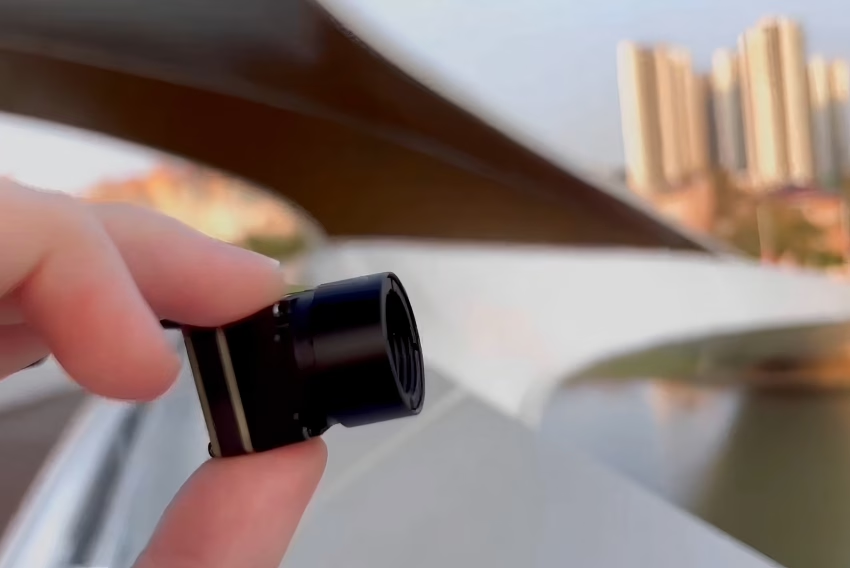
Jak wybrać najlepszy moduł kamery termowizyjnej na podczerwień do dronów, Raspberry Pi i integracji Edge AI
Streszczenie wykonawcze i zasady architektury na poziomie systemu
Ewolucja technologii niechłodzonych czujników długofalowej podczerwieni (LWIR) przeszła od ciężkich, energochłonnych zespołów klasy wojskowej do ultrakompaktowych modułów o wysokiej rozdzielczości moduły kamer termowizyjnych zaprojektowanych do integracji z bezzałogowymi statkami powietrznymi (UAV), komputerami jednopłytkowymi (SBC) i silnikami sztucznej inteligencji brzegowej. Dla inżynierów elektroników, integratorów systemów i architektów oprogramowania wybór odpowiedniego rdzenia termowizyjnego to nie tylko kwestia wyboru rozdzielczości. Wymaga to głębokiego zrównoważenia budżetów wagowych, interfejsów elektrycznych, protokołów danych i czułości termicznej (NETD).
Aby poruszać się w tym krajobrazie, niniejszy przewodnik wdrożeniowy analizuje fizyczne, elektryczne i obliczeniowe wymagania integracji wysokowydajnych modułów LWIR. Porównując surowe interfejsy, takie jak MIPI CSI-2, ze strumieniami enkapsulowanymi sieciowo, takimi jak RJ45 RTSP/IP, niniejszy przewodnik dostarcza dokładnych kryteriów potrzebnych do wdrożenia niechłodzonych matryc mikrobolometrycznych w złożonych środowiskach wieloczujnikowych.
Poprzez systematyczną ocenę charakterystyk optycznych, potoków sprzętowych, interfejsów programowych i ograniczeń fizycznych, zespoły ds. rozwoju systemów mogą zoptymalizować swoje projekty detekcji termicznej. Niniejszy dokument przedstawia fizyczne zasady stojące za akwizycją surowego sygnału długofalowej podczerwieni, szczegółowo opisuje podstawowe różnice między bezpośrednią manipulacją rejestrami a konfiguracjami strumieniowania sieciowego oraz zapewnia wskazówki krok po kroku dotyczące realizacji integracji sprzętowych.
Spis treści
- 👉 Fizyczne i optyczne podstawy modułów termicznych LWIR
- 👉 Interfejsy elektryczne i protokoły wideo: MIPI CSI-2 vs. RTSP/IP
- 👉 Szczegółowe prezentacje produktów: Specyfikacje techniczne i karty katalogowe
- 👉 Przewodnik integracji z Raspberry Pi krok po kroku
- 👉 Przemysłowe wdrożenie Edge AI i rdzeń fuzji wieloczujnikowej
- 👉 Pogłębione najczęściej zadawane pytania (FAQ)
Fizyczne i optyczne podstawy modułów termicznych LWIR
Opracowanie przemysłowego systemu termowizyjnego wymaga solidnego zrozumienia fizyki, inżynierii materiałowej i inżynierii optycznej. Niechłodzone moduły kamer termowizyjnych działają w paśmie długofalowej podczerwieni (LWIR), zazwyczaj w zakresie od 8 μm do 14 μm. W przeciwieństwie do kamer światła widzialnego, które opierają się na odbitych fotonach, czujniki LWIR wykrywają samoistne promieniowanie cieplne emitowane przez obiekty, które jest wprost proporcjonalne do ich bezwzględnej temperatury termodynamicznej, zgodnie z prawem Plancka i prawem Stefana-Boltzmanna.
1 Rozdzielczość, rozmiar piksela i format czujnika
Sercem niechłodzonej kamery termowizyjnej jest jej matryca mikrobolometryczna w płaszczyźnie ogniskowej (FPA). Nowoczesne FPA są wytwarzane przy użyciu cienkowarstwowych rezystorów z tlenku wanadu (VOx) lub amorficznego krzemu (α-Si) osadzonych na krzemowym układzie scalonym odczytu (ROIC).
Oto jak kształtują się główne wybory architektoniczne na płytce:
- ⚙️ Rozdzielczość: Standardowe konfiguracje termowizyjne obejmują matryce pikseli 256×192, 384×288 i 640×512. Rozdzielczość bezpośrednio dyktuje szczegółowość przestrzenną sceny. Matryca 640×512 zawiera 327 680 pojedynczych detektorów mikrobolometrycznych, oferując surowy kontekst przestrzenny odpowiedni do poszukiwań i ratownictwa z dronów, zautomatyzowanych inspekcji paneli słonecznych oraz złożonych potoków detekcji obiektów w ramach brzegowej sztucznej inteligencji.
- ⚙️ Rozstaw pikseli: Oznacza to odległość między środkami sąsiednich elementów detektora na matrycy czujnika, mierzoną w mikrometrach (μm). Branża przeszła z matryc 17 μm na 12 μm. Zmniejszenie rozmiaru piksela pozwala na mniejszy rozmiar struktury krzemowej, obniżając całkowitą wagę i koszt produkcji czujnika. Jednak mniejszy rozmiar piksela zmniejsza również aktywną powierzchnię przechwytywania każdego piksela, wymagając wyższej wydajności optycznej (niższej liczby przysłony) i zaktualizowanych algorytmów wzmocnienia czujnika, aby utrzymać wysoką czułość termiczną.
2 Zrozumienie parametrów optycznych: ogniskowa, pole widzenia i liczba przysłony
Ponieważ szkło pochłania energię LWIR, niechłodzone moduły podczerwieni wykorzystują specjalistyczne soczewki wykonane z monokrystalicznego germanu (Ge) lub szkła chalkogenidowego, wraz z powłokami antyrefleksyjnymi (AR).
- ⚙️ Ogniskowa (f): Mierzona w odległościach poszukiwawczych i rozmieszczeniowych, ogniskowa kontroluje zarówno kątowe pole widzenia (FOV), jak i chwilowe pole widzenia (IFOV). IFOV reprezentuje rozdzielczość przestrzenną pojedynczego piksela w określonej odległości (d):
IFOV = Rozmiar piksela / fUżycie obiektywu 9 mm na czujniku 12 μm daje IFOV:
IFOV = (12 * 10^-6 m) / (9 * 10^-3 m) = 1,33 mradOznacza to, że w odległości 100 metrów pojedynczy piksel rozróżnia obszar 13,3 cm.
- ⚙️ Pole widzenia (FOV): Obliczane na podstawie fizycznego rozmiaru czujnika (szerokość × wysokość) i ogniskowej obiektywu (f), obliczenia poziomego (H_FOV) i pionowego (V_FOV) pola widzenia wyrażane są jako:
θ = 2 * arctan(W / (2 * f))Układ o rozdzielczości 640×512 z pikselem 12 μm ma aktywną szerokość czujnika 7,68 mm (640 * 12 μm). W połączeniu z obiektywem 9 mm osiąga szerokie poziome pole widzenia około 46,2°, co czyni go wysoce wydajnym do mapowania szerokich obszarów z dronów i monitorowania infrastruktury energetycznej z powietrza.
- ⚙️ Przysłona (liczba przysłony): Oznaczana jako F/1.0, F/1.2 lub F/1.3, jest to stosunek ogniskowej obiektywu do średnicy źrenicy wejściowej. Ponieważ energia cieplna emitowana z celów otoczenia jest niska, systemy optyczne LWIR wymagają jasnych przysłon (zazwyczaj F/1.0 do F/1.2), aby zmaksymalizować zbieranie fotonów:
Strumień cieplny docierający do FPA ∝ 1 / (F/#)^2Obiektyw F/1.0 dostarcza dwukrotnie więcej energii cieplnej do matrycy czujnika w porównaniu z obiektywem F/1.4, znacznie poprawiając jakość obrazu modułu i ogólny stosunek sygnału do szumu.
3 Czułość termiczna (NETD) i profile kalibracyjne
Równoważna szumowi różnica temperatur (NETD) definiuje minimalną różnicę temperatur, którą może rozróżnić niechłodzony czujnik mikrobolometryczny. Reprezentuje granicę szumu systemu, gdzie stosunek sygnału do szumu wynosi jeden (S/N = 1), mierzoną w milikelwinach (mK).
- ⚙️ Wzorzec przemysłowy: NETD <50 mK (przy 25°C, F/1.0) to standard branżowy dla modułów o wysokiej wydajności. Wysokiej klasy komponenty, takie jak nowoczesne niechłodzone rdzenie, osiągają czułości ≤40 mK. Niższe wartości NETD przekładają się bezpośrednio na czystsze profile termiczne, zredukowany szum typu „sól i pieprz” oraz lepsze profile zasięgu w warunkach niskiego kontrastu (takich jak dni pochmurne lub deszczowe).
- ⚙️ Kalibracja (NUC): Mikrobolometry LWIR są bardzo wrażliwe na temperaturę samego korpusu kamery, która może dryfować i powodować zmiany wzmocnień między pikselami w czasie. Aby utrzymać prawidłowe, wolne od dryftu obrazy, moduły implementują korekcję niejednorodności (NUC). Wykonuje się ją za pomocą wewnętrznej mechanicznej migawki (lub algorytmów bezmigawkowych do specjalnych zastosowań), aby ponownie skalibrować FPA względem jednolitego źródła temperatury.
- ⚙️ Formaty danych (8-bitowy vs. 14-bitowy): W zastosowaniach wizji maszynowej i pomiaru temperatury niechłodzony rdzeń generuje dwa podstawowe formaty danych:
- ✅ 14-bitowe surowe dane cyfrowe (Y14): Zapewnia bezpośrednie wyjście cyfrowe proporcjonalne do surowej radiancji lub skalibrowanej temperatury każdego piksela. Ten strumień o wysokiej przepływności jest kluczowy w zastosowaniach radiometrycznych, umożliwiając programistom obliczanie temperatur bezwzględnych w szerokim zakresie dynamicznym (np. od -20°C do +150°C lub +550°C).
- ✅ 8-bitowe skompresowane wideo (YUV422 / Mono8 / RGB): Generowane przez przepuszczenie 14-bitowego sygnału surowego przez zautomatyzowane algorytmy zakresu dynamicznego, takie jak Wyrównanie Histogramu Adaptacyjnego z Ograniczeniem Kontrastu (CLAHE). To skompresowane wyjście jest przeznaczone do bezpośredniej wizualizacji i obserwacji przez człowieka.
Interfejsy elektryczne i protokoły wideo: MIPI CSI-2 vs. RTSP/IP
Podczas integracji modułu kamery termowizyjnej na podczerwień z platformą wbudowaną, wybór fizycznego interfejsu elektrycznego stanowi kluczowy krok architektoniczny.
1 Dogłębna analiza MIPI CSI-2 (Mobile Industry Processor Interface)
MIPI CSI-2 to szybki, punkt-punkt, różnicowy interfejs szeregowy opracowany dla mobilnych i wbudowanych systemów kamer.
- ⚙️ Warstwa fizyczna: Działa w oparciu o warstwę fizyczną MIPI D-PHY, wykorzystując jedną szybką linię zegarową synchroniczną ze źródłem oraz jedną lub więcej różnicowych linii danych.
- ⚙️ Trasowanie sygnałów i integralność: Linie różnicowe MIPI muszą być precyzyjnie dopasowane długością (z tolerancją niedopasowania w granicach 0,1 mm) i prowadzone z dala od linii wysokiej częstotliwości (takich jak impulsowe regulatory mocy lub ścieżki szybkiej pamięci RAM), aby zapobiec zakłóceniom elektromagnetycznym. Niezrównoważenie impedancji ścieżek (która powinna być utrzymywana na poziomie 100 Ω różnicowo ±10%) może degradować pakiety danych, powodując gubienie klatek lub problemy z synchronizacją w strumieniu wideo.
- ⚙️ Analiza opóźnień: MIPI CSI-2 omija lokalne kodeki kompresji, przesyłając surowe formaty wideo (takie jak RAW8, RAW10, RAW12, RAW14 lub YUV422) bezpośrednio do pamięci procesora hosta za pośrednictwem bezpośredniego dostępu do pamięci (DMA). Zapewnia to minimalne opóźnienie (zazwyczaj <5 ms opóźnienia propagacji), które jest niezbędne w pętlach sterowania lotem drona w zamkniętej pętli, systemach unikania przeszkód i wysoce responsywnych gimbalach kamer.
- ⚙️ Konfiguracja sterownika: Podłączenie modułu termowizyjnego MIPI w systemie Linux wymaga załadowania odpowiedniego sterownika do jądra za pomocą Device Tree Blob (DTB). Sterownik ten rejestruje moduł termowizyjny w podsystemie Video4Linux2 (V4L2), umożliwiając programistom odpytywanie funkcji kamery i zmianę profili przechwytywania za pomocą standardowych wywołań ioctl.
2 RJ45 Ethernet, RTSP i potoki strumieniowania oparte na IP
W systemach, w których czujnik termowizyjny jest zainstalowany z dala od głównej jednostki przetwarzającej (na przykład na wysokich wieżach bezpieczeństwa, dużych przemysłowych ramionach robotów lub rozległych platformach dronów), MIPI CSI-2 jest ograniczony swoim krótkim zasięgiem transmisji (zazwyczaj <15 cm bez dedykowanych aktywnych buforów sygnałowych). W takich scenariuszach preferowanym podejściem są konfiguracje RJ45 IP i RTSP.
- ⚙️ Warstwa fizyczna Ethernet: Wykorzystuje standardowe układy nadawczo-odbiorcze warstwy fizycznej 100Base-TX/1000Base-T (PHY) do niezawodnej transmisji danych sieciowych na odległość do 100 metrów przy użyciu standardowej miedzianej skrętki (kable Cat5e/Cat6).
- ⚙️ Kodowanie kompresyjne na miejscu: Dedykowany układ ASIC lub System-on-Chip (SoC) umieszczony w module kamery przechwytuje surowe dane z czujnika, przetwarza je i kompresuje przy użyciu standardowych standardów wideo, takich jak H.264 lub H.265. Ten etap kodowania wprowadza niewielkie opóźnienie (zazwyczaj od 80 ms do 150 ms) w zależności od liczby klatek na sekundę, odstępów między klatkami kluczowymi (GoP) i wydajności kodera.
- ⚙️ Protokoły strumieniowania sieciowego:
- ✅ Jest to standardowy format telewizji analogowej. Praktycznie nie ma opóźnień transmisji i łączy się bezpośrednio z dalekosiężnymi analogowymi nadajnikami dronów. Wadą jest to, że wymaga zewnętrznego układu konwertera analogowo-cyfrowego do połączenia z Raspberry Pi, co stanowi dodatkowy punkt awarii i pogarsza klarowność obrazu. Zarządza połączeniem strumienia wideo, obsługując działania sterujące systemem, takie jak odtwarzanie, pauza i rozłączanie.
- ✅ RTP (Protokół transportu czasu rzeczywistego): Pakuje skompresowane klatki H.264/H.265 w pojedyncze pakiety sieciowe UDP, wysyłając je do docelowych klientów w czasie rzeczywistym.
- ✅ RTCP (Protokół kontrolny RTP): Monitoruje jakość transmisji, dostarczając informacji zwrotnych o utracie pakietów i jitterze, aby pomóc koderowi wideo dynamicznie dostosowywać przepływność.
- ⚙️ Integracja z oprogramowaniem IoT i bezpieczeństwa: Ponieważ moduł działa jako standardowe urządzenie sieciowe, integruje się bezpośrednio ze standardowymi systemami zarządzania wideo (VMS), takimi jak Milestone, Qognify, oraz oprogramowaniem open-source, takim jak ZoneMinder, a także bibliotekami programistycznymi, takimi jak OpenCV (
cv2.VideoCapture("rtsp://...")). Pozwala to kamerze na bezpośrednie podłączenie do istniejącej infrastruktury sieciowej bez potrzeby stosowania specjalistycznych sterowników niskopoziomowych.
3 Porównawcza macierz interfejsów dla architektów sprzętu
| Metryka / Parametr | Interfejs MIPI CSI-2 | Interfejs RJ45 Ethernet / RTSP / IP |
|---|---|---|
| Format danych | Surowe dane cyfrowe (Y14 14-bit / YUV422 8-bit) | Strumień skompresowany (H.264 / H.265) |
| Odległość transmisji | <15 cm (wymaga krótkich płaskich taśm elastycznych) | Do 100 metrów (wykorzystuje standardowe okablowanie sieciowe) |
| Opóźnienie systemowe | Bezpośredni DMA (<5 ms) | Opóźnienie kompresji/dekompresji (80 ms - 150 ms) |
| Użycie zasobów hosta | Wysokie obciążenie CPU przy konwersji surowych pikseli na temperaturę | Niskie obciążenie CPU (dekodowanie przez GPU lub bloki sprzętowe) |
| Waga/Współczynnik okablowania | Mikrocienki kabel Flex (idealny do lekkich gimbali) | Kabel ekranowany Cat5e/Cat6 (grubszy i cięższy) |
| Routing wielu kamer | Wymaga dedykowanych linii sprzętowych na CPU | Standardowy routing sieciowy przez komercyjne przełączniki Ethernet |
| Integracja sterowników | Niskopoziomowy sterownik jądra i niestandardowa konfiguracja skompilowanego DTB | Uniwersalna kompatybilność sieciowa; strumieniowanie przez standardowe gniazda |
W celu uzyskania dalszych projektów systemów technicznych i zaawansowanych konfiguracji dronów wieloprotokołowych, patrz Blog Purpleriver Drone Integration Thermal.
Szczegółowe prezentacje produktów: Specyfikacje techniczne i karty katalogowe
Wybór niechłodzonego rdzenia czujnika LWIR wymaga analizy parametrów fizycznych i elektronicznych z arkuszy danych producenta. Poniżej znajdują się dwa reprezentatywne moduły, pokazujące różnicę między surowym, lekkim interfejsem MIPI CSI-2 a zintegrowanym rdzeniem strumieniowania sieciowego RJ45.
1 Moduł Purpleriver Mini2 640x512 9mm LWIR MIPI
to cud inżynierii zaprojektowany specjalnie do środowisk o ograniczonych parametrach SWaP. Dzięki miniaturyzacji elektroniki bez poświęcania jakości sensora dostarczamy rdzeń, który mieści się w najciaśniejszych przestrzeniach. Moduł kamery termowizyjnej Purpleriver Mini2 640x512 9mm niechłodzonej podczerwieni MIPI został zaprojektowany specjalnie do zastosowań z ograniczeniami SWaP (rozmiar, waga i moc), takich jak lekkie ładunki wielowirnikowych UAV i kompaktowe urządzenia przenośne.
Niechłodzona kamera termowizyjna Mini2 640x512 9mm do dronów charakteryzuje się ostrym i wyraźnym obrazem, niezwykle kompaktowymi rozmiarami i niskim kosztem. Wyprowadza 14-bitowy strumień cyfrowy bezpośrednio przez lekki interfejs MIPI, eliminując niepotrzebne obciążenie przetwarzania. Umożliwia to bezpośrednie pomiary temperatury przy jednoczesnym utrzymaniu absolutnie minimalnej wagi.
- ✅ Główne zastosowania: Lekkie ładunki do dronów, mapowanie termiczne, kompaktowe ręczne systemy diagnostyczne, gimbale do mikro-UAV.
- ✅ Kluczowa zaleta: Niezwykle kompaktowa obudowa o wymiarach 21 mm × 21 mm. Może być integrowana bezpośrednio w bezszczotkowych gimbalach bez wpływu na kinetykę stabilizacji.
Wyświetl szczegóły produktu i ceny ➔
2 Moduł termowizyjny Purpleriver 640x512 ASIC RJ45 RTSP IP
to cud inżynierii zaprojektowany specjalnie do środowisk o ograniczonych parametrach SWaP. Dzięki miniaturyzacji elektroniki bez poświęcania jakości sensora dostarczamy rdzeń, który mieści się w najciaśniejszych przestrzeniach. Moduł kamery termowizyjnej Purpleriver niechłodzony na podczerwień RJ45 CVBS RTSP IP 640*512 ASIC zawiera wbudowany układ scalony specyficzny dla aplikacji (ASIC) zaprojektowany do przetwarzania, kompresji i strumieniowania wideo termicznego bezpośrednio przez standardową infrastrukturę sieciową.
Oto sedno: z tym modułem nie tracisz dni na tworzenie niestandardowych procedur strojenia obrazu. Pętla przetwarzania jest wbudowana bezpośrednio w module, pozwalając procesorowi hosta skupić się na rzeczywistej logice automatyzacji wysokiego poziomu.
Ten moduł zapewnia zintegrowane rozwiązanie z interfejsami RJ45 Ethernet, CVBS analogowym i wideo RTSP. Posiada wbudowany układ ASIC, który obsługuje zaawansowane przetwarzanie obrazu, korekcję niejednorodności (NUC) i zoom cyfrowy w samym module kamery. Umożliwia to bezpośrednie strumieniowanie sieciowe przez RTSP z niskim opóźnieniem, zmniejszając wymagania przetwarzania kontrolera hosta.
- ✅ Główne zastosowania: Ciągłe monitorowanie obiektów, zautomatyzowana robotyka, ochrona obwodowa, optyczno-termiczne układy śledzenia pan-tilt.
- ✅ Kluczowa zaleta: Zintegrowane interfejsy fizyczne. Podwójnie ułożona płytka przetwarzająca działa jako samodzielny serwer punktu końcowego wideo, usprawniając integrację oprogramowania przez IP.
Wyświetl szczegóły produktu i ceny ➔
3 Pełna macierz specyfikacji sprzętowej
| Kryteria diagnostyczne | Moduł Purpleriver Mini2 640x512 9mm MIPI | Moduł Purpleriver 640x512 ASIC RJ45 RTSP IP |
|---|---|---|
| Materiały detektora | Niechłodzony mikrobolometr z tlenku wanadu (VOx) | Niechłodzony mikrobolometr z tlenku wanadu (VOx) |
| Rozdzielczość matrycy | 640 × 512 pikseli | 640 × 512 pikseli |
| Rozstaw pikseli | 12 μm | 12 μm |
| Zakres spektralny | 8 μm do 14 μm (LWIR) | 8 μm do 14 μm (LWIR) |
| Czułość termiczna (NETD) | ≤ 40 mK (przy 25°C, F/1.0) | ≤ 40 mK (przy 25°C, F/1.0) |
| Częstotliwość odświeżania | Opcje 25 Hz / 50 Hz | 25 Hz |
| Wybór obiektywu | Zintegrowany zespół obiektywu 9mm | Opcje germanowe (obsługiwane 9mm, 13mm, 19mm) |
| Dynamiczne interfejsy wideo | MIPI CSI-2 (złącze FPC 15-pin) | RJ45 Ethernet, CVBS (analogowy), sterowanie UART |
| Obsługiwany Zakres Temperatur | -20°C do +150°C (opcja do +550°C) | Standardowy zakres -20°C do +150°C |
| Dokładność temperaturowa | ± 2°C lub ± 2% aktywnego odczytu | ± 2°C lub ± 2% aktywnego odczytu |
| Pobór mocy | ≤ 1,2 W podczas ciągłego strumieniowania | ≤ 2,0 W (ze względu na działanie PHY sieci i ASIC) |
| Waga (przybliżona) | < 15 gramów (bez zewnętrznego zespołu obiektywu) | < 55 gramów (posiada dynamiczną wytrzymałą obudowę) |
| Wymiary fizyczne | 21 mm × 21 mm × 11,5 mm | 38 mm × 38 mm × 28,5 mm |
Poznaj pełną gamę niechłodzonych modułów i akcesoriów do kamer bezpośrednio na Katalog sklepów Purpleriver.
Przewodnik integracji z Raspberry Pi krok po kroku
Połączenie surowej magistrali równoległej niechłodzonego czujnika LWIR Purpleriver Mini2 640 MIPI ze standardowym komputerem jednopłytkowym, takim jak Raspberry Pi (Model 4B, 5 lub Compute Module 4), wymaga starannego zaplanowania wyprowadzeń sprzętowych, konfiguracji jądra i integracji sterowników.
1 Interfejs sprzętowy i konfiguracje wyprowadzeń
Moduł Purpleriver Mini2 640 MIPI zapewnia 15-pinowy interfejs FPC (płaski elastyczny kabel), który prowadzi szybkie pary różnicowe MIPI wraz z rejestrami parametrów I2C, sygnałami sterującymi i wejściami zasilania systemowego.
- ⚙️ Ścieżki MIPI: Pary różnicowe danych i zegara muszą być podłączone bezpośrednio do złącza wejściowego odbiornika kamery na płytce Raspberry Pi. Użyj ekranowanej taśmy FPC o kontrolowanej impedancji, zaprojektowanej specjalnie do szybkich sygnałów kamer.
- ⚙️ Linie zarządzania I2C: Podłącz piny sterujące kamery
I2C_SDAiI2C_SCLbezpośrednio do pinów sprzętowej magistrali I2C Raspberry Pi (zazwyczaj GPIO 2 i GPIO 3). Piny te umożliwiają Raspberry Pi komunikację z wewnętrzną przestrzenią rejestrów modułu termicznego, umożliwiając kontrolę operacji takich jak ręczna kalibracja (NUC), stany wzmocnienia i konfiguracje skali temperatury. - ⚙️ Wymagania dotyczące zasilania: Moduł kamery termowizyjnej wymaga czystego źródła zasilania +3,3 V o niskim poziomie tętnień. Wszelkie szumy na liniach zasilających mogą pogorszyć czułe pomiary matrycy mikrobolometrycznej FPA. Aby zabezpieczyć się przed artefaktami pikseli wywołanymi szumem, należy odsprzęgnąć linię zasilania +3,3 V za pomocą kondensatora 10 μF o niskim ESR równolegle z kondensatorem ceramicznym 0,1 μF, umieszczonych jak najbliżej złącza FPC kamery.
2 Konfiguracja stosu oprogramowania dla Raspberry Pi (potok MIPI)
Aby włączyć surowy potok niechłodzonego rdzenia termicznego, należy skonfigurować opcje rozruchu Raspberry Pi, aby załadować poprawną nakładkę sterownika pomocniczego i przydzielić wystarczającą ilość pamięci dla strumienia wideo o wysokiej przepustowości.
W systemie operacyjnym Raspberry Pi edytuj plik konfiguracji sprzętowej systemu /boot/firmware/config.txt (lub /boot/config.txt w starszych systemach operacyjnych):
# Otwórz plik konfiguracji sprzętowej do edycji
Dodaj następujące linie konfiguracyjne, aby aktywować poddrzewo sterownika kamery i skonfigurować podział pamięci systemowej:
# Włącz sprzętowy interfejs magistrali I2C
Zapisz plik (Ctrl+O, następnie Wkracza), wyjdź (Ctrl+X) i uruchom ponownie Raspberry Pi, aby zastosować nowe konfiguracje:
sudo reboot
Sprawdź, czy system poprawnie wykrywa niestandardowy moduł termiczny i wyświetla go w natywnej infrastrukturze multimedialnej Linux:
# Zapytaj narzędzie V4L2, aby wyświetlić listę aktywnych kontrolerów multimediów i formatów
Powinieneś zobaczyć wynik reprezentujący zweryfikowaną rejestrację sprzętu:
Purpleriver Camera (platform:bcm2835-unicam):
3 Skrypt aplikacji Python do ekstrakcji temperatury 14-bitowej
Po zarejestrowaniu kamery na /dev/video0, możesz uzyskać dostęp do strumienia danych pikseli. Ten skrypt Python używa OpenCV i Numpy do odczytu surowych, 14-bitowych radiometrycznych wartości cyfrowych (Y14) z kamery, ekstrakcji bezwzględnych temperatur rzeczywistych i wyświetlania strumienia wideo termicznego.
import cv2
import numpy as np

def init_thermal_capture(device_index=0):
    if nie cap.isOpened():
        raise IOError(f"Nie można uzyskać dostępu do niechłodzonego węzła wideo w /dev/video")

    # Skonfiguruj tryb surowych danych pikseli 14-bitowych przy użyciu standardowego kodeka fourcc
    cap.set(cv2.CAP_PROP_FOURCC, cv2.VideoWriter_fourcc(*'Y14 ')), 640), 512)
    return cap

def convert_raw_to_celsius(raw_frame):
    # Zastosuj standardowy wzór liniowy: Temp (C) = (Raw_Value / 64.0) - 273.15
    celsius_grid = (raw_radiometric / 64.0) - 273.15
    return celsius_grid

def main():
    try:0)"Potok surowych danych radiometrycznych uruchomiony. Naciśnij 'q', aby wyjść.")

        while True:
            if nie ret:"Nie udało się przechwycić klatki.")
                break

            raw_data = frame.view(dtype=np.uint16).reshape((512, 640)) 256, 320
            center_temp = temperatures[center_y, center_x], None, 0, 255, cv2.NORM_MINMAX, dtype=cv2.CV_8U) f"Temperatura środka: {center_temp:.2f} C"
            cv2.circle(color_mapped_image, (center_x, center_y), 5, (0, 255, 0), 1)20, 40), 0.8, (255, 255, 255), 2, cv2.LINE_AA)"Radiometryczny strumień termiczny", color_mapped_image)

            if cv2.waitKey(1) & 0xFF == ord('q'):
                break

    except Exception as err:f"Błąd wykonania systemu: {err}")
    finally:
        if 'cap' w locals():

if __name__ == "__main__":
Przemysłowe wdrożenie Edge AI i rdzeń fuzji wieloczujnikowej
Integracja modułu niechłodzonej kamery termowizyjnej w przemysłowym potoku wizji maszynowej wymaga możliwości przetwarzania wykraczających poza proste mapowanie kolorów. Rzeczywiste systemy brzegowe łączą niechłodzone rdzenie LWIR ze strumieniami kamer światła widzialnego (RGB) i wdrażają zaawansowane modele głębokiego uczenia bezpośrednio na urządzeniach brzegowych, takich jak platforma NVIDIA Jetson.
1 Integracja modułów LWIR z NVIDIA Jetson Orin Nano / Xavier
Architektura NVIDIA Jetson wykorzystuje sprzętowo przyspieszane potoki GStreamer do przetwarzania strumieni wideo o wysokiej rozdzielczości w czasie rzeczywistym przy minimalnym obciążeniu CPU. Potoki te zapisują ramki wideo bezpośrednio do zunifikowanej pamięci systemowej (NVMM) w celu akceleracji GPU.
Aby odbierać strumień z modułu kamery Purpleriver 640x512 RJ45 RTSP ze sprzętowo przyspieszanym dekodowaniem, programiści mogą zainicjować OpenCV przy użyciu tej zoptymalizowanej konfiguracji potoku GStreamer:
import cv2

def get_jetson_rtsp_pipeline(rtsp_url, target_width=640, target_height=512):
    1TP5% Zoptymalizowany potok GStreamer wykorzystujący sprzętowy dekoder NVDEC Jetsona
    gst_pipeline = (
        f"rtspsrc location={rtsp_url} latency=50 ! "
        "rtph264depay ! "
        "h264parse ! "
        "nvv4l2decoder ! "
        f"nvvideoconvert ! "
        f"video/x-raw(memory:NVMM), width={target_width}, height={target_height}, format=BGRx ! "
        "nvvidconv ! "
        "video/x-raw, format=BGR ! "
        "appsink drop=true sync=false"
    )
    return cv2.VideoCapture(gst_pipeline, cv2.CAP_GSTREAMER)
Integracja modeli wykrywania celów, takich jak YOLOv8, na niechłodzonych strumieniach wideo termowizyjnych pozwala systemom brzegowym na niezawodną klasyfikację celów (takich jak ludzie lub dzika przyroda) w złożonych warunkach, w tym w całkowitej ciemności, mgle lub zapyleniu.
2 Fuzja wielosensorowa: wyrównanie RGB i LWIR
Częstym wyzwaniem w instalacjach inspekcji dronów i monitorowania perymetrycznego jest dopasowanie szerokiego pola widzenia kamery światła widzialnego (RGB) do węższego, czułego termicznie pola widzenia niechłodzonego sensora LWIR. Ponieważ sensory są fizycznie oddzielone, ich strumienie obrazu wykazują przestrzenną niezgodność (błąd paralaksy).
Aby rozwiązać ten błąd paralaksy, można użyć macierzy transformacji homografii planarnej (H) do wyrównania i nałożenia obrazu termicznego na źródło obrazu światła widzialnego. Ta macierz 3×3 jest obliczana podczas kalibracji systemu poprzez dopasowanie współpłaszczyznowych punktów odniesienia w obu przestrzeniach obrazu.
import cv2
import numpy as np

def perform_sensor_homography_warp(lwir_frame, rgb_frame, H_matrix):
    """
    height_rgb, width_rgb, _ = rgb_frame.shape

    return fused_image
Stosując ten etap kalibracji i wyrównania, systemy autonomiczne mogą analizować i potwierdzać cele w obu spektrach – termicznym i widzialnym – znacznie redukując liczbę fałszywych alarmów podczas procedur poszukiwania celów.
Pogłębione najczęściej zadawane pytania (FAQ)
Jak wybrać najlepszy interfejs (MIPI vs. RJ45/RTSP) dla modułu kamery termowizyjnej do drona?
Czy mogę połączyć ten moduł kamery termowizyjnej na podczerwień z Raspberry Pi lub Arduino?
Dlaczego warto przejść ze standardowych czujników hobbystycznych na moduły przemysłowe Purpleriver?
Jak tłumienie atmosferyczne wpływa na niechłodzone kamery termowizyjne w zastosowaniach dronowych dalekiego zasięgu?
Jaki jest cel migawki korekcji niejednorodności (NUC) i czy można ją pominąć?
📚 Piśmiennictwo i dalsze lektury
- Przemysłowe Standardowe Zasoby Sprzętowe: Katalog Sprzętu KUYANG
- Części Ekosystemu Prototypowania Wbudowanego: Czujniki i Akcesoria DFRobot
- Wytyczne i Algorytmy Integracji z Dronami: Blog Purpleriver Drone Integration Thermal