









Best Thermal Camera Module for Drone Integration: Guide for B2B OEMs
2026年7月2日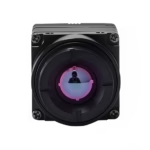
640 512 35mm Thermal Camera Module: The Ultimate B2B Integration Guide for Drones and Edge AI
2026年7月3日
How to Choose the Best Infrared Thermal Imaging Camera Module for Drones, Raspberry Pi, and Edge AI Integration
Executive Summary & System-Level Architectural Principles
The evolution of uncooled long-wave infrared (LWIR) sensor technology has transitioned from heavy, power-hungry military-grade assemblies to ultra-compact, high-resolution infrared thermal imaging camera modules designed for integration into unmanned aerial vehicles (UAVs), single-board computers (SBCs), and edge artificial intelligence engines. For electronics engineers, systems integrators, and software architects, selecting the correct thermal imaging core is not merely a matter of choosing a resolution. It requires a deep balancing of weight budgets, electrical interfaces, data protocols, and thermal sensitivity (NETD).
To navigate this landscape, this deployment guide analyzes the physical, electrical, and computational requirements of integrating high-performance LWIR modules. By comparing raw interfaces like MIPI CSI-2 with network-encapsulated streams like RJ45 RTSP/IP, this guide provides the exact criteria needed to deploy uncooled microbolometer arrays in complex, multi-sensor environments.
Through systematic evaluation of optical characteristics, hardware pipelines, software interfaces, and physical constraints, systems development teams can optimize their thermal sensing designs. This document outlines the physical principles behind raw long-wave infrared signal acquisition, details the underlying differences between direct register manipulation and network streaming configurations, and provides step-by-step guidance for actualizing hardware integrations.
Table of Contents
- 👉 1. Physical & Optical Fundamentals of LWIR Thermal Modules
- 👉 2. Electrical Interfaces & Video Protocols: MIPI CSI-2 vs. RTSP/IP
- 👉 3. Detailed Product Showcases: Technical Specifications & Data Sheets
- 👉 4. Step-by-Step Raspberry Pi Integration Guide
- 👉 5. Industrial Edge AI Deployment & Multi-Sensor Fusion Core
- 👉 6. Deep-Dive Frequently Asked Questions (FAQ)
1. Physical & Optical Fundamentals of LWIR Thermal Modules
Developing an industrial-grade thermal imaging system requires a solid understanding of physics, material science, and optical engineering. Uncooled thermal imaging camera modules operate in the Long-Wave Infrared (LWIR) band, typically ranging from 8 μm to 14 μm. Unlike visible light cameras that rely on reflected photons, LWIR sensors detect self-emitted thermal radiation from objects, which is directly proportional to their absolute thermodynamic temperature as described by Planck's Law and the Stefan-Boltzmann Law.
1.1 Resolution, Pixel Pitch, and Sensor Format
The core of an uncooled thermal camera is its Microbolometer focal plane array (FPA). Modern FPAs are fabricated using vanadium oxide (VOx) or amorphous silicon (α-Si) thin-film resistors deposited on a silicon read-out integrated circuit (ROIC).
Here is how the main architectural choices shake out on the board:
- ⚙️ Resolution: Standard thermal imaging configurations include 256×192, 384×288, and 640×512 pixel arrays. The resolution directly dictates the spatial detail of the scene. A 640×512 array contains 327,680 individual microbolometer detectors, offering raw spatial context suitable for drone-based search and rescue, automated solar panel inspections, and complex edge artificial intelligence object-detection pipelines.
- ⚙️ Pixel Pitch: This denotes the center-to-center distance between adjacent detector elements on the sensor array, measured in micrometers (μm). The industry has transitioned from 17 μm down to 12 μm arrays. Reducing the pixel pitch allows a smaller silicon die size, lowering the overall weight and manufacturing cost of the sensor. However, a smaller pixel pitch also reduces the active capture area of each pixel, demanding higher optical performance (lower f-number) and updated sensor gain algorithms to maintain high thermal sensitivity.
1.2 Understanding Optical Parameters: Focal Length, FOV, and f-number
Because glass absorbs LWIR energy, uncooled infrared modules use specialized lenses made of monocrystalline Germanium (Ge) or Chalcogenide glass, complete with anti-reflective (AR) coatings.
- ⚙️ Focal Length (f): Measured in search and deployment distances, the focal length controls both the angular Field of View (FOV) and the Instantaneous Field of View (IFOV). The IFOV represents the spatial resolution of a single pixel at a specific distance (d):
IFOV = Pixel Pitch / fUsing a 9mm lens on a 12 μm sensor yields an IFOV of:
IFOV = (12 * 10^-6 m) / (9 * 10^-3 m) = 1.33 mradThis means that at a distance of 100 meters, a single pixel resolves an area of 13.3 cm.
- ⚙️ Field of View (FOV): Calculated using the physical sensor size (Width × Height) and the lens focal length (f), the horizontal (H_FOV) and vertical (V_FOV) calculations are expressed as:
θ = 2 * arctan(W / (2 * f))A 640×512 resolution chip with a 12 μm pitch has an active sensor width of 7.68 mm (640 * 12 μm). Coupled with a 9mm lens, it achieves a wide horizontal FOV of roughly 46.2°, making it highly efficient for wide-area drone mapping and aerial utility monitoring.
- ⚙️ Aperture (f-number): Designated as F/1.0, F/1.2, or F/1.3, it is the ratio of the lens focal length to the diameter of the entrance pupil. Because the thermal energy emitted from ambient targets is low, LWIR optical systems require fast apertures (typically F/1.0 to F/1.2) to maximize photon collection:
Thermal Flux reaching FPA ∝ 1 / (F/#)^2An F/1.0 lens delivers double the thermal energy to the sensor array compared to an F/1.4 lens, significantly improving the module's image quality and overall signal-to-noise ratio.
1.3 Thermal Sensitivity (NETD) and Calibration Profiles
Noise Equivalent Temperature Difference (NETD) defines the minimum temperature difference that the uncooled microbolometer sensor can resolve. It represents the noise limit of the system, where the signal-to-noise ratio equals one (S/N = 1), measured in millikelvins (mK).
- ⚙️ Industrial Benchmark: An NETD of <50 mK (at 25°C, F/1.0) is the industry standard for high-performance modules. High-end components like modern uncooled cores achieve sensitivities of ≤40 mK. Lower NETD values translate directly to cleaner thermal profiles, reduced salt-and-pepper noise, and better range profiles during low-contrast conditions (such as on overcast or rainy days).
- ⚙️ Calibration (NUC): LWIR microbolometers are highly sensitive to the temperature of the camera body itself, which can drift and cause pixel-to-pixel gains to shift over time. To maintain correct, drift-free images, modules implement Non-Uniformity Correction (NUC). This is performed using an internal mechanical shutter (or shutterless algorithms for dedicated applications) to recalibrate the FPA against a uniform temperature source.
- ⚙️ Data Formats (8-bit vs. 14-bit): For machine vision and temperature measurement, the uncooled core produces two primary data formats:
- ✅ 14-bit Digital Raw Data (Y14): Provides a direct digital output proportional to the raw radiance or calibrated temperature of each pixel. This high-bitrate stream is crucial for radiometric applications, allowing developers to calculate absolute temperatures across a wide dynamic range (e.g., -20°C to +150°C or +550°C).
- ✅ 8-bit Compressed Video (YUV422 / Mono8 / RGB): Generated by passing the 14-bit raw signal through automated dynamic range algorithms, such as Contrast Limited Adaptive Histogram Equalization (CLAHE). This compressed output is designed for direct visualization and human observation.
2. Electrical Interfaces & Video Protocols: MIPI CSI-2 vs. RTSP/IP
When integrating an infrared thermal imaging camera module into an embedded platform, selection of the physical electrical interface represents a key architectural step.
2.1 MIPI CSI-2 (Mobile Industry Processor Interface) Deep Dive
MIPI CSI-2 is a high-speed, point-to-point, differential serial interface developed for mobile and embedded camera systems.
- ⚙️ Physical Layer: Operates over the MIPI D-PHY physical layer, utilizing one high-speed source-synchronous clock lane and one or more differential data lanes.
- ⚙️ Signal Routing and Integrity: MIPI differential trace lines must be precisely length-matched (within 0.1 mm mismatch tolerance) and kept away from high-frequency lines (such as switching power regulators or high-speed RAM pathways) to prevent electromagnetic interference. Imbalance in trace impedance (which should be maintained at 100 Ω differential ±10%) can degrade data packets, resulting in frame drops or synchronization issues in the video feed.
- ⚙️ Latency Analysis: MIPI CSI-2 bypasses local compression codecs, streaming raw video formats (such as RAW8, RAW10, RAW12, RAW14, or YUV422) directly into the Host processor's memory via Direct Memory Access (DMA). This provides minimal latency (typically <5 ms propagation delay), which is essential for closed-loop drone flight control adjustments, hazard evasion systems, and highly responsive camera gimbals.
- ⚙️ Driver Configuration: Interfacing a MIPI thermal module using Linux requires loading a matching driver into the kernel via a Device Tree Blob (DTB). This driver registers the thermal module with the Video4Linux2 (V4L2) sub-system, allowing developers to query camera features and change capture profiles via industry-standard ioctl calls.
2.2 RJ45 Ethernet, RTSP, and IP-Based Streaming Pipelines
For systems where the thermal sensor is installed far from the primary processing unit (such as on tall security towers, large industrial robotic arms, or expansive drone platforms), MIPI CSI-2 is limited by its short transmission range (typically <15 cm without dedicated active signal buffers). In these scenarios, RJ45 IP and RTSP configurations are the preferred approach.
- ⚙️ Ethernet Physical Layer: Uses standard 100Base-TX/1000Base-T physical layer transceiver circuits (PHYs) to transmit network data reliably over distances up to 100 meters using standard copper Twisted Pair (Cat5e/Cat6) cables.
- ⚙️ Onsite Compression Encoding: A dedicated onsite ASIC or System-on-Chip (SoC) sitting within the camera module captures raw sensor data, processes it, and compresses it using standard video standards like H.264 or H.265. This encoding step introduces a slight delay (typically 80 ms to 150 ms) depending on frame rate, keyframe intervals (GoP), and the performance of the encoder.
- ⚙️ Network Streaming Protocols:
- ✅ RTSP (Real-Time Streaming Protocol): Manages the video stream connection, supporting system control actions like play, pause, and teardown.
- ✅ RTP (Real-time Transport Protocol): Packages the H.264/H.265 compressed frames into individual UDP network packets, sending them to target clients in real time.
- ✅ RTCP (RTP Control Protocol): Monitors transmission quality, providing feedback on packet loss and jitter to help the video encoder dynamically adjust its bitrate.
- ⚙️ Integration with IoT and Security Software: Because the module acts as a standard network device, it integrates directly with standard Video Management Systems (VMS) like Milestone, Qognify, and open-source software like ZoneMinder, as well as developer libraries like OpenCV (
cv2.VideoCapture("rtsp://...")). This allows the camera to plug directly into pre-existing network infrastructure without needing specialized low-level device drivers.
2.3 Comparative Interface Matrix for Hardware Architects
| Metric / Parameter | MIPI CSI-2 Interface | RJ45 Ethernet / RTSP / IP Interface |
|---|---|---|
| Data Format | Raw Digital (Y14 14-bit / YUV422 8-bit) | Compressed Stream (H.264 / H.265) |
| Transmission Distance | <15 cm (requires short flat flex cables) | Up to 100 meters (utilizes standard network cabling) |
| System Latency | Direct DMA (<5 ms) | Compression/Decompression Delay (80 ms - 150 ms) |
| Host Resource Usage | High CPU overhead for raw pixel-to-temperature conversion | Low CPU overhead (decoded via GPU or hardware-accelerated blocks) |
| Cabling Weight/Factor | Micro-thin Flex Cable (ideal for lightweight gimbals) | Cat5e/Cat6 Shielded Cable (thicker and heavier) |
| Multi-Camera Routing | Requires dedicated hardware lanes on the CPU | Standard network routing via commercial Ethernet switches |
| Driver Integration | Low-level kernel driver & custom DTB compiled configuration | Universal network compatibility; streams via standard sockets |
For further technical system designs and advanced multi-protocol drone configurations, refer to the Purpleriver Drone Integration Thermal Blog.
3. Detailed Product Showcases: Technical Specifications & Data Sheets
Selecting an uncooled LWIR sensor core requires analyzing physical and electronic parameters from the manufacturer's data sheets. Below are two representative modules, showcasing the distinction between a raw, lightweight MIPI CSI-2 interface and an integrated RJ45 network-streaming core.
3.1 Purpleriver Mini2 640x512 9mm LWIR MIPI Module
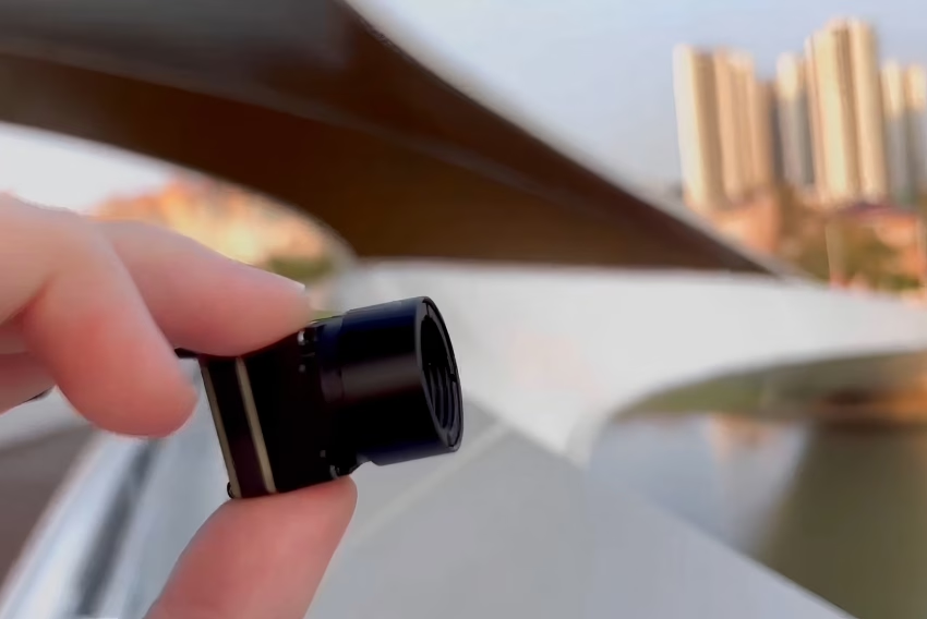
The Purpleriver Mini2 640x512 9mm Uncooled Infrared MIPI Thermal Imaging Camera Module is engineered specifically for SWaP-constrained (Size, Weight, and Power) applications, such as lightweight multirotor UAV payloads and compact handheld devices.
Uncooled Infrared Mini2 640x512 9mm Thermal Imaging Camera Module For Drones features sharp and crisp image presentation, extremely compact size, and low cost. It outputs a 14-bit digital stream directly via a lightweight MIPI interface, removing unnecessary processing overhead. This allows for direct temperature measurements while keeping weight to an absolute minimum.
- ✅ Primary Applications: Lightweight drone payloads, thermal mapping, compact hand-held diagnostic systems, micro-UAV gimbals.
- ✅ Key Advantage: Extremely compact 21 mm × 21 mm physical footprint. Can be integrated directly into brush-less gimbals without affecting stabilization kinetics.
View Product Details & Pricing ➔
3.2 Purpleriver 640x512 ASIC RJ45 RTSP IP Thermal Module
The Purpleriver Uncooled Infrared RJ45 CVBS RTSP IP 640*512 ASIC Thermal Sensor Camera Module incorporates an onboard Application-Specific Integrated Circuit (ASIC) designed to process, compress, and stream thermal video directly over standard network infrastructure.
Here's the deal: with this module, you aren't wasting days cooking up custom image tuning routines. The processing loop is hardwired right on the module, letting your host processor focus on actual high-level automation logic.
This module provides an integrated solution with RJ45 Ethernet, CVBS analog, and RTSP video. Features an onboard ASIC that handles advanced image processing, non-uniformity correction (NUC), and digital zoom within the camera module itself. This allows for direct network streaming via RTSP with low latency, dropping the processing requirements of the host controller.
- ✅ Primary Applications: Continuous facility monitoring, automated robotics, perimeter security, optical-thermal pan-tilt tracking arrays.
- ✅ Key Advantage: Integrated physical interfaces. The double-stacked processing board acts as a standalone video endpoint server, streamlining software integration over IP.
View Product Details & Pricing ➔
3.3 Complete Hardware Specification Matrix
| Diagnostic Criteria | Purpleriver Mini2 640x512 9mm MIPI Module | Purpleriver 640x512 ASIC RJ45 RTSP IP Module |
|---|---|---|
| Detector Materials | Uncooled Vanadium Oxide (VOx) Microbolometer | Uncooled Vanadium Oxide (VOx) Microbolometer |
| Array Resolution | 640 × 512 pixels | 640 × 512 pixels |
| Pixel Pitch | 12 μm | 12 μm |
| Spectral Range | 8 μm to 14 μm (LWIR) | 8 μm to 14 μm (LWIR) |
| Thermal Sensitivity (NETD) | ≤ 40 mK (at 25°C, F/1.0) | ≤ 40 mK (at 25°C, F/1.0) |
| Frame Rate | 25 Hz / 50 Hz options | 25 Hz |
| Lens Selection | 9mm integrated lens assembly | Germanium selections (9mm, 13mm, 19mm supported) |
| Dynamic Video Interfaces | MIPI CSI-2 (15-pin FPC connector) | RJ45 Ethernet, CVBS (Analog), UART Control |
| Temperature Range Support | -20°C to +150°C (up to +550°C option) | -20°C to +150°C standard range |
| Temperature Accuracy | ± 2°C or ± 2% of the active reading | ± 2°C or ± 2% of the active reading |
| Power Consumption | ≤ 1.2 W during continuous streaming | ≤ 2.0 W (due to network PHY and ASIC operation) |
| Weight (Approximate) | < 15 grams (without external lens assembly) | < 55 grams (features dynamic rugged housing) |
| Physical Dimensions | 21 mm × 21 mm × 11.5 mm | 38 mm × 38 mm × 28.5 mm |
Explore the full range of uncooled modules and camera accessories directly on the Purpleriver Shop Directory.
4. Step-by-Step Raspberry Pi Integration Guide
Interfacing the Purpleriver Mini2 640 MIPI uncooled LWIR sensor raw parallel bus with a standard single-board computer like the Raspberry Pi (Model 4B, 5, or Compute Module 4) requires careful planning of hardware pinouts, kernel configuration, and driver integration.
4.1 Hardware Interfacing & Pinout Configurations
The Purpleriver Mini2 640 MIPI module provides a 15-pin FPC (Flat Flexible Cable) interface that routes high-speed MIPI differential pairs alongside I2C parameter registers, control signals, and system power inputs.
- ⚙️ MIPI Paths: The differential data and clock lanes must be connected directly to the camera receiver input connector on the Raspberry Pi board. Use a shielded, impedance-controlled FPC ribbon cable designed specifically for high-speed camera signals.
- ⚙️ I2C Management Lines: Connect the camera's
I2C_SDAandI2C_SCLcontrol pins directly to the Raspberry Pi's hardware I2C bus pins (typically GPIO 2 and GPIO 3). These pins allow the Raspberry Pi to communicate with the thermal module's internal register space, enabling control of operations like manual calibration (NUC), gain states, and temperature scale configurations. - ⚙️ Power Requirements: The thermal camera module requires a clean, low-ripple +3.3V power source. Any noise on the power lines can degrade the sensitive measurements of the microbolometer FPA. To protect against noise-induced pixel artifacts, decouple the +3.3V supply line with a low-ESR 10 μF capacitor in parallel with a 0.1 μF ceramic capacitor, placed as close to the camera FPC connector as possible.
4.2 Software Stack Configuration for Raspberry Pi (MIPI Pipeline)
To enable the uncooled thermal core raw pipeline, you must configure the Raspberry Pi's boot options to load the correct helper driver overlay and allocate enough memory for the high-bandwidth video stream.
On the Raspberry Pi OS, edit the system hardware configuration file /boot/firmware/config.txt (or /boot/config.txt on older operating systems):
# Open the hardware configurations file for editing
sudo nano /boot/firmware/config.txt
Add the following configuration lines to activate the camera driver sub-tree and configure the system memory split:
# Enable the hardware I2C bus interface
dtparam=i2c_arm=on

# Set the GPU memory allocation to at least 128MB to handle high-resolution frames
gpu_mem=128

# Load the Purpleriver raw camera driver overlay
# This registers the module under the Video4Linux2 sub-system
dtoverlay=purpleriver-mini2-mipi,csi-lanes=2
Save the file (Ctrl+O, then Enter), exit (Ctrl+X), and reboot the Raspberry Pi to apply the new configurations:
sudo reboot
Verify that the system detects the custom thermal module correctly and lists it under the native Linux media infrastructure:
# Query the V4L2 utility to list active media controllers and formats
v4l2-ctl --list-devices
You should see an output representing the verified hardware registration:
Purpleriver Camera (platform:bcm2835-unicam):
    /dev/video0
4.3 Python Application Script for 14-bit Temperature Extraction
Once the camera is registered on /dev/video0, you can access the pixel data stream. This Python script uses OpenCV and Numpy to read the raw, 14-bit radiometric digital values (Y14) from the camera, extract absolute real-world temperatures, and display the thermal video stream.
import cv2
import numpy as np

def init_thermal_capture(device_index=0):
    cap = cv2.VideoCapture(device_index, cv2.CAP_V4L2)
    if not cap.isOpened():
        raise IOError(f"Unable to access the uncooled video node at /dev/video")

    # Configure raw 14-bit pixel data mode using standard fourcc codec
    cap.set(cv2.CAP_PROP_FOURCC, cv2.VideoWriter_fourcc(*'Y14 '))
    cap.set(cv2.CAP_PROP_FRAME_WIDTH, 640)
    cap.set(cv2.CAP_PROP_FRAME_HEIGHT, 512)
    return cap

def convert_raw_to_celsius(raw_frame):
    raw_radiometric = raw_frame.astype(np.float32)
    # Apply standard linear formula: Temp (C) = (Raw_Value / 64.0) - 273.15
    celsius_grid = (raw_radiometric / 64.0) - 273.15
    return celsius_grid

def main():
    try:
        cap = init_thermal_capture(0)
        print("Raw radiometric data pipeline started. Press 'q' to exit.")

        while True:
            ret, frame = cap.read()
            if not ret:
                print("Failed to capture frame.")
                break

            raw_data = frame.view(dtype=np.uint16).reshape((512, 640))
            temperatures = convert_raw_to_celsius(raw_data)

            center_y, center_x = 256, 320
            center_temp = temperatures[center_y, center_x]

            norm_frame = cv2.normalize(raw_data, None, 0, 255, cv2.NORM_MINMAX, dtype=cv2.CV_8U)
            color_mapped_image = cv2.applyColorMap(norm_frame, cv2.COLORMAP_IRONBOW)

            text_label = f"Center Temp: {center_temp:.2f} C"
            cv2.circle(color_mapped_image, (center_x, center_y), 5, (0, 255, 0), 1)
            cv2.putText(color_mapped_image, text_label, (20, 40),
                        cv2.FONT_HERSHEY_SIMPLEX, 0.8, (255, 255, 255), 2, cv2.LINE_AA)

            cv2.imshow("Radiometric Thermal Stream", color_mapped_image)

            if cv2.waitKey(1) & 0xFF == ord('q'):
                break

    except Exception as err:
        print(f"System execution failure: {err}")
    finally:
        if 'cap' in locals():
            cap.release()
        cv2.destroyAllWindows()

if __name__ == "__main__":
    main()
5. Industrial Edge AI Deployment & Multi-Sensor Fusion Core
Integrating an uncooled thermal imaging camera module into an industrial machine vision pipeline requires processing capabilities beyond simple color mapping. Real-world edge systems combine uncooled LWIR cores with visible-light (RGB) camera streams and deploy advanced deep learning models directly on edge devices, such as the NVIDIA Jetson platform.
5.1 Integrating LWIR Modules with NVIDIA Jetson Orin Nano / Xavier
The NVIDIA Jetson architecture utilizes hardware-accelerated GStreamer pipelines to process high-resolution video streams in real time with minimal CPU utilization. These pipelines write video frames directly into unified system memory (NVMM) for GPU acceleration.
To stream from the Purpleriver 640x512 RJ45 RTSP camera module with hardware-accelerated decoding, developers can initialize OpenCV using this optimized GStreamer pipeline configuration:
import cv2

def get_jetson_rtsp_pipeline(rtsp_url, target_width=640, target_height=512):
    # Optimized GStreamer pipeline using Jetson's hardware NVDEC decoder
    gst_pipeline = (
        f"rtspsrc location={rtsp_url} latency=50 ! "
        "rtph264depay ! "
        "h264parse ! "
        "nvv4l2decoder ! "
        f"nvvideoconvert ! "
        f"video/x-raw(memory:NVMM), width={target_width}, height={target_height}, format=BGRx ! "
        "nvvidconv ! "
        "video/x-raw, format=BGR ! "
        "appsink drop=true sync=false"
    )
    return cv2.VideoCapture(gst_pipeline, cv2.CAP_GSTREAMER)

# Connect using configured network coordinates
rtsp_feed = "rtsp://192.168.1.150:554/stream1"
cap = get_jetson_rtsp_pipeline(rtsp_feed)
Integrating target-detection models like YOLOv8 on uncooled thermal video feeds allows edge systems to reliably classify targets (such as humans or wildlife) in complex conditions, including total darkness, fog, or dust.
5.2 Multi-Sensor Fusion: RGB and LWIR Alignment
A common challenge in drone inspection and perimeter monitoring installations is matching the wide field of view of a visible light (RGB) camera with the narrower, thermally-sensitive field of view of an uncooled LWIR sensor. Because the sensors are physically separated, their image streams have spatial misalignment (parallax error).
To resolve this parallax error, you can use a planar homography transformation matrix (H) to align and overlay the thermal image onto the visible-light image source. This 3×3 matrix is calculated during system calibration by matching co-planar reference points in both image spaces.
import cv2
import numpy as np

def perform_sensor_homography_warp(lwir_frame, rgb_frame, H_matrix):
    """
    Warps and aligns an uncooled thermal frame (640x512) to match
    the coordinate space of a high-resolution visible-light RGB frame.
    """
    height_rgb, width_rgb, _ = rgb_frame.shape

    # Warp the thermal frame to match the coordinate perspective of the RGB image
    warped_thermal = cv2.warpPerspective(lwir_frame, H_matrix, (width_rgb, height_rgb))

    # Combine the aligned frames using a 60/40 transparency blend
    fused_image = cv2.addWeighted(rgb_frame, 0.6, warped_thermal, 0.4, 0)

    return fused_image

# Example 3x3 homography matrix calculated during calibration
H_test = np.array([
    [1.15, -0.02, 120.0],
    [0.01,  1.12,  85.0],
    [0.00,  0.00,   1.0]
], dtype=np.float32)
By applying this calibration alignment step, autonomous systems can analyze and confirm targets across both thermal and visible spectrums, significantly reducing false-positive rates during target search procedures.
6. Deep-Dive Frequently Asked Questions (FAQ)
How do I choose the best interface (MIPI vs. RJ45/RTSP) for a drone thermal camera module?
Can I interface this infrared thermal imaging camera module with a Raspberry Pi or Arduino?
Why upgrade from standard hobbyist sensors to Purpleriver's industrial modules?
How does atmospheric attenuation affect uncooled thermal cameras in long-range drone applications?
What is the purpose of the Non-Uniformity Correction (NUC) shutter, and can it be bypassed?
📚 References & Further Reading
- Industrial Standard Hardware Resources: KUYANG Hardware Catalog
- Embedded Prototyping Ecosystem Parts: DFRobot Sensors & Accessories
- Drone Integration Guidelines & Algorithms: Purpleriver Drone Integration Thermal Blog





