High-Performance Infrared Core Guide: Compact LWIR Modules for OEM & Drones
2026年8月10日
Industrial Thermal Sensor Selection Guide: OEM AI Camera Modules & B2B Integration
2026年8月11日
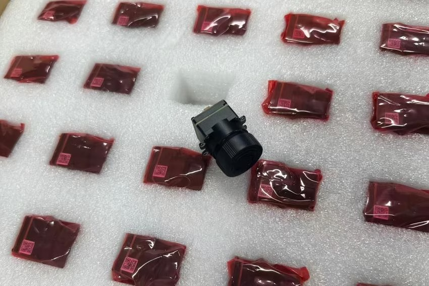
High-Performance Infrared Core Buyer's Guide: Custom Thermal Sensor Modules for AI Vision
Look, as edge computing and autonomous platforms take off, slapping an infrared core into a multi-sensor rig has gone from a niche defense capability to everyday engineering for commercial AI vision systems. Thermal vision systems operate completely independent of light. They cut right through pitch darkness, thick fog, heavy smoke, and blowing dust by capturing raw radiant heat in the Long-Wave Infrared (LWIR) spectrum (8–14 μm). But here's the deal: dropping a microbolometer-based thermal engine onto power-starved drones, field robotics, or edge IoT boxes isn't plug-and-play. It throws serious mechanical, thermal, electrical, and optical design hurdles straight at your team. You have to balance Size, Weight, Power, and Cost (SWaP-C) against signal-to-noise ratios, frame rates, interface throughput, and optical diffraction limits without cooking your electronics.
This architectural buyer's guide breaks down the underlying physics, hardware topologies, and interface protocols driving modern uncooled Vanadium Oxide (VOx) thermal engines. We're going to dig into the real-world trade-offs of pixel pitch scaling (moving from 17μm down to 12μm), unpack digital image processing pipelines running on dedicated Application-Specific Integrated Circuits (ASICs), and compare sensor-level digital interfaces like MIPI CSI-2 against networked IP streams like RTSP over RJ45. Whether you're building long-range aerial surveillance gimbals or training real-time thermal defect recognition models, this guide gives you the pragmatic blueprint to pick, integrate, and tune an uncooled infrared core for next-generation edge vision.
Table of Contents
- 👉 1. Understanding the Modern Infrared Core: Physics, Microbolometer Arrays, and Spectral Response
- 👉 2. Hardware Architecture: VOx Sensing, Pixel Pitch, and ASIC Image Processing Engines
- 👉 3. Hardware Interfaces for AI Vision: MIPI CSI-2 vs. Ethernet/RTSP vs. CVBS
- 👉 4. Thermal Optics Engineering: Germanium vs. Chalcogenide Lenses for LWIR Systems
- 👉 5. System Integration & SWaP-C Optimization in Drones and Edge IoT
- 👉 6. Commercial-Grade Infrared Core Comparison & Specifications
- 👉 7. Frequently Asked Questions (FAQ)
1. Understanding the Modern Infrared Core: Physics, Microbolometer Arrays, and Spectral Response
An infrared core—often called a thermal OEM engine, camera engine, or microbolometer module—is the raw electro-optical heart of any thermal system. Its job is simple to describe but hard to execute: pull non-visible thermal radiation out of the air and turn it into calibrated digital temperature maps or clean video feeds. Unlike standard CMOS or CCD sensors that rely on photons striking silicon to liberate electrons via the photoelectric effect, an uncooled thermal sensor is a MEMS (Micro-Electro-Mechanical Systems) microbolometer array that physically measures absorbed thermal heat energy.
The physics behind an uncooled infrared core ties straight back to Planck’s Law of Blackbody Radiation and Wien’s Displacement Law. At standard earthly temperatures (-40°C to +150°C), peak thermal radiation sits squarely inside the Long-Wave Infrared (LWIR) atmospheric transmission window between 8 μm and 14 μm. In this specific waveband, signal absorption by atmospheric water vapor and carbon dioxide drops off significantly. That means heat signatures travel long distances without getting wiped out by ambient weather.
In the shop, if you zoom down to the pixel level on a microbolometer, you'll find a microscopic absorbing bridge suspended above a silicon substrate by paper-thin support legs. These legs do double duty: they anchor the bridge mechanically and run electrical pathways to the readout circuitry underneath, all while keeping the pixel membrane thermally isolated from the substrate. If heat leaks out through the legs too fast, your thermal sensitivity goes out the window.
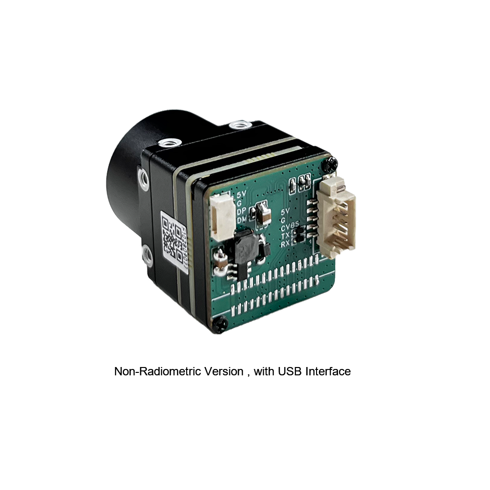
When long-wave heat radiation hits that suspended absorbing bridge, the bridge's temperature jumps relative to the silicon base below. That slight thermal delta changes the electrical resistance of the thin-film material inside the bridge. How much that resistance swings per degree of temperature change is defined by the material's Temperature Coefficient of Resistance (TCR):
In high-grade uncooled cores, manufacturers almost exclusively use Vanadium Oxide (VOx) thin films instead of older Amorphous Silicon (a-Si). Here's why VOx wins out: it gives you a higher Temperature Coefficient of Resistance (~2% to 3% per Kelvin), drops 1/f flicker noise way down, and features thermal time constants between 8ms and 12ms. As heat accumulates on the VOx film, the Readout Integrated Circuit (ROIC) fires a fast bias pulse through the pixel array. The resistance change alters the current flow, which gets caught by internal capacitors on the ROIC, sampled, and digitized by high-speed ADCs into uncompressed 14-bit or 16-bit digital thermal counts.
2. Hardware Architecture: VOx Sensing, Pixel Pitch, and ASIC Image Processing Engines
To drop uncooled LWIR sensors into real-time embedded systems, sensor builders sandwich the microbolometer Focal Plane Array (FPA), ROIC, thermal stabilization components, and a dedicated vision ASIC into a tight hardware stack. What your vision pipeline can actually accomplish comes down to how well these sub-components are tuned to work together.
Pixel Pitch Scaling and Optical Modulation Transfer Function (MTF)
The thermal world spent years working with 25μm and 17μm pixels, but the modern baseline has firmly shifted down to 12μm arrays. Shrinking the pixel pitch shrinks the overall physical size of the Focal Plane Array for any given spatial resolution. Case in point: a 640×512 array on a 12μm pitch takes up an active image diagonal of roughly 9.8mm, whereas an older 17μm array needed almost 14mm. Shrinking that image circle lets optical engineers shrink lens diameters, drop focal length requirements, and strip massive weight off the primary glass assembly.
However, physics always demands a tax. Smaller microbolometer pixels mean less physical surface area to collect incoming photon flux. A 12μm pixel has roughly half the surface area of a 17μm pixel, meaning it captures far fewer photons under identical scene conditions. To keep the sensor's Modulation Transfer Function (MTF) from collapsing and maintain crisp edge clarity, system engineers have to run ultra-low-noise Readout Integrated Circuits (ROICs) and pair the core with wider optical apertures (f/1.0 to f/1.2).
Noise Equivalent Temperature Difference (NETD)
Noise Equivalent Temperature Difference (NETD) is the key metric for thermal sensitivity. It defines the smallest thermal delta the core can pull out of the noise floor, measured in millikelvins (mK). Run-of-the-mill industrial cores sit around 50mK, but high-performance sensor engines push NETD values down under 30mK to 40mK (tested at f/1.0, 300K reference temperature, 30Hz frame rates).
In field conditions with low thermal contrast—like high-humidity rain, overcast skies, or thermally uniform concrete landscapes—a lower NETD keeps background noise from obscuring image detail. For computer vision algorithms, low NETD maintains clean object contours and high gradient definitions. That means your convolutional neural networks (CNNs) spend processing cycles identifying actual target boundaries instead of filtering sensor hiss.
ASIC-Driven Hardware Image Processing Pipeline
Raw pixel data coming off an uncooled microbolometer array looks rough. Manufacturing micro-variances across millions of suspended MEMS bridges introduce significant non-uniformity. A dedicated hardware thermal ASIC sits right next to the sensor array to clean up these anomalies before handing off frames to the host board:
- ⚙️ Non-Uniformity Correction (NUC): This stage flattens gain and offset variations across every single pixel in the array. Modern modules combine dynamic mechanical shutter passes with continuous shutterless math routines, keeping your video feed running smooth without dropping frames during critical tracking events.
- ⚙️ Dead Pixel Replacement (DPR): The ASIC dynamically flags dead, stuck, or noisy pixels on the fly, swapping their corrupt values out for clean interpolated spatial data pulled from surrounding operational pixels.
- ⚙️ Adaptive Dynamic Range Compression & DDE: Thermal scenes feature massive dynamic ranges (14-bit raw values covering hundreds of degrees). The ASIC applies Digital Detail Enhancement (DDE) and localized contrast algorithms (like CLAHE) to squeeze high-dynamic 14-bit data down to standard 8-bit visual streams without flattening target edges or blowing out highlights.
If you're digging into low-level microbolometer register setups or building custom ISP firmware, take a look at our practical guide on 384x288 thermal module camera integration strategies for low-level register maps and timing considerations.
3. Hardware Interfaces for AI Vision: MIPI CSI-2 vs. Ethernet/RTSP vs. CVBS
Picking the right electrical interface controls how cleanly your infrared core moves frame data into downstream AI chips (like NVIDIA Jetson, Rockchip RK3588, or Raspberry Pi) or onboard telemetry units.
1. MIPI CSI-2 (Mobile Industry Processor Interface)
If you're building tight, low-latency embedded payloads or lightweight drone setups, MIPI CSI-2 is the hands-down standard. Pushing uncompressed 14-bit raw counts or hardware-processed 8-bit frames over differential high-speed data lanes, MIPI CSI-2 connects direct to the Image Signal Processor (ISP) or memory bus on your edge System-on-Chip (SoC).
By dumping pixel buffers straight into host RAM over Direct Memory Access (DMA), MIPI CSI-2 bypasses video encoding latency entirely. You can hit glass-to-glass pipeline speeds under 10ms. That makes MIPI CSI-2 the clear winner for real-time robotic obstacle avoidance, rapid gimbal tracking, and tight control-loop navigation. To keep things compact, board-to-board hookups generally use high-density connectors engineered by Hirose Electric, which hold differential impedance steady while saving precious board space.
For hands-on kernel driver implementation on Linux embedded boards, check out our driver walkthrough on setting up RS300 V4L2 drivers on Raspberry Pi.
2. Ethernet (RJ45 / RTSP / IP / ONVIF)
Ethernet thermal engines pack an onboard encoding chip that compresses raw frames straight into standard H.264 or H.265 video feeds. These cores push IP streams over standard TCP/IP network hardware via RTSP, supporting ONVIF Profile S/T compliance out of the box.
Ethernet interfaces fit fixed site security, heavy industrial monitoring platforms, and dual-sensor IP enclosures. You can run long cable drops without signal degradation, and developers get instant access to built-in web GUIs to tweak color palettes, adjust emissivity numbers, or set up temperature threshold alarms.
3. CVBS (Composite Video Blanking and Sync)
CVBS outputs old-school analog video (NTSC or PAL) over simple coaxial or two-wire setups. While it's great for quick bench testing or throwing a direct feed to a cheap analog FPV display, CVBS crushes rich 14-bit thermal data down into a squished 8-bit analog composite signal. It works fine for direct operator monitoring, but it's a dead end for quantitative computer vision pipelines.
4. Thermal Optics Engineering: Germanium vs. Chalcogenide Lenses for LWIR Systems
Standard glass optics (like BK7 or silica) act like solid brick walls to long-wave thermal radiation—8–14μm heat waves can't pass through them. To focus thermal energy onto a microbolometer, you need specialized transmissive materials.
| Optical & Physical Material Property | Single-Crystal Germanium (Ge) | Chalcogenide Glass (Ge-Sb-Se) |
|---|---|---|
| Refractive Index (at 10μm LWIR) | ~4.00 (Exceptionally High) | ~2.50 - 2.80 |
| Material Density | 5.33 g/cm³ | 4.40 - 4.65 g/cm³ (15% - 20% Lighter) |
| Thermal Runaway Temperature Limit | Degrades above ~100°C (Becomes Opaque) | Stable performance across broader ranges |
| Manufacturing Process | Single-point diamond turning (SPDT) | Precision Glass Molding (PGM) |
| Cost Profile at High Production Volumes | High material and machining costs | Significantly lower unit cost via molding |
Optical Properties & Material Choice
Single-crystal Germanium (Ge) is the classic choice thanks to its sky-high refractive index (n ≈ 4.0). That high index lets lens designers bend thermal rays sharply using thin, low-aberration elements with wide apertures. But Germanium isn't cheap, and it suffers from a major weakness: thermal runaway. As operational temperatures climb past 100°C, Germanium's absorption coefficient spikes through the roof, turning crystal-clear lenses opaque.
To cut BOM costs and scale volume manufacturing, suppliers like LightPath Technologies turn to molded Chalcogenide glass. Chalcogenide elements are amorphous compounds blending Germanium, Selenium, Antimony, and Tellurium. Because Chalcogenide optics can be pressed repeatedly using automated Precision Glass Molding (PGM), unit costs plummet once you ramp production volumes.
Even better, Chalcogenide glass exhibits lower thermal dispersion swings (lower dn/dT) than raw Germanium. Mixing Chalcogenide optical elements with tuned aluminum-alloy housing barrels lets optical designers build athermalized lens assemblies. These passive optics stay locked in focus across wild thermal swings (-40°C to +80°C) without needing heavy motorized focus drivers.
5. System Integration & SWaP-C Optimization in Drones and Edge IoT
When you're fitting an uncooled infrared core into weight-sensitive drone gimbals or field IoT enclosures, Size, Weight, Power, and Cost (SWaP-C) dictate every design decision.
- ✅ Payload Weight & Gimbal Inertia: In flight platforms, every gram counts against battery burn time. Modern ultra-compact 640×512 thermal engines trim down under 21 × 21 × 21 mm and weigh less than 30 grams stripped of optics. Keeping mass minimal lowers rotational inertia, letting 3-axis brushless gimbals cancel out airframe vibration and high-speed wind buffeting smoothly.
- ✅ Power Budget Management: Uncooled VOx engines pull a tiny fraction of the power required by cryo-cooled photon detectors. A typical uncooled core sips between 0.8W and 1.5W off a 3.3V to 5V DC rail. That low power draw keeps board temperatures down and extends flight times on battery systems.
- ✅ Heat Sinks & Structural Thermal Paths: Microbolometers rely on heat conduction through the frame to dump internal thermal energy created by the ASIC and ROIC. If heat clusters unevenly inside the core, localized thermal gradients creep across the array, causing spatial drift and washed-out regions in your video feed.
In the field, you fix this by installing high-conductivity thermal interface materials (TIMs) bonded straight from the core chassis to your outer structural frame. Sinking internal heat out into the vehicle's metal frame keeps sensor thermal distribution flat, cutting down on automatic shutter recalibrations and keeping target detection rock solid.
For physical footprint layouts and mechanical mounts, check out our mechanical integration teardown on ultra-compact 640x512 high-sensitivity thermal camera module design.
6. Commercial-Grade Infrared Core Comparison & Specifications
Below are two field-tested uncooled infrared core architectures built specifically for integration into commercial drones, edge compute rigs, and networked thermal platforms.

Uncooled Infrared MIPI 640 384 256 9mm Thermal Imaging Camera Module For Drones
The Mini2 series is an ultra-compact VOx thermal imaging engine tuned specifically for weight-critical payloads. Packing a native 640x512 array on a tight 12μm pixel pitch alongside a high-transmittance 9mm germanium objective, this module pushes high spatial detail while cutting chassis weight to the bone. Equipped with a direct MIPI CSI-2 digital interface, it routes raw 14-bit or enhanced 8-bit frames straight into host AI processors with virtually zero pipeline latency.
- ⚙️ Array Resolution: 640 × 512 pixels (384×288 and 256×192 variants available)
- ⚙️ Pixel Pitch: 12μm VOx Uncooled Microbolometer
- ⚙️ Primary Output Interface: MIPI CSI-2 Digital Output
- ⚙️ Lens Optics: 9mm Fixed Athermalized Objective Lens
- ⚙️ Thermal Sensitivity: NETD < 40mK (@ f/1.0, 300K)

Uncooled Infrared RJ45 CVBS RTSP IP 640*512 Thermal Sensor Camera Module
Engineered for perimeter security installations and networked IoT setups, this ASIC-driven core supports direct IP streaming, analog feeds, and complete non-uniformity correction right out of the box. With an integrated RTSP server and ONVIF compliance, the core handles H.265/H.264 compression internally and pushes clean video over an RJ45 Ethernet link while simultaneously feeding a secondary CVBS signal to local analog displays.
- ⚙️ Array Resolution: 640 × 512 pixels
- ⚙️ Pixel Pitch: 12μm VOx Sensor Technology
- ⚙️ Output Interfaces: RJ45 Ethernet (IP/RTSP/ONVIF) + CVBS Analog
- ⚙️ Onboard Processing: ASIC Hardware Engine (H.264/H.265 Compression)
- ⚙️ Target Field: Industrial Monitoring, Fixed Perimeter AI, PTZ Enclosures
Comprehensive Product Technical Comparison Matrix
| Specification Metric | Mini2 MIPI 640x512 Module | RJ45/RTSP 640x512 ASIC Module |
|---|---|---|
| Sensor Resolution | 640 × 512 pixels | 640 × 512 pixels |
| Pixel Pitch & Material | 12μm Vanadium Oxide (VOx) | 12μm Vanadium Oxide (VOx) |
| Spectral Response | 8 μm to 14 μm (LWIR) | 8 μm to 14 μm (LWIR) |
| Output Interface Protocols | MIPI CSI-2 (Direct to Host SoC) | Ethernet RJ45 (RTSP/IP/ONVIF) & CVBS Analog |
| Pipeline Latency | < 10 ms (Ultra-Low Latency) | ~120 - 200 ms (Network Compression Overhead) |
| Optical Lens Configuration | 9mm Fixed Objective Lens | Athermalized Lens Options Available |
| Typical Power Draw | < 1.0 Watt | < 1.8 Watts |
| Target Application Profile | Drone Gimbals, Robotics, Edge AI Vision | Perimeter Security, Fixed IoT, Monitoring Systems |
7. Frequently Asked Questions (FAQ)
Why do commercial infrared cores often have lower resolution and frame rates compared to visible light cameras?
Here's the deal: thermal cameras don't look at visible light photons hitting standard silicon. They rely on micro-machined MEMS bolometer bridges to absorb raw long-wave heat energy (LWIR, 8–14μm). Every single pixel on a thermal sensor is a tiny mechanical bridge suspended over a substrate on fine support legs to isolate it thermally.
If you try pushing thermal sensors up to 4K or 1080p resolutions, the die size explodes, or you have to squeeze pixel pitches below 10μm. Shrinking thermal pixels reduces the physical surface area available to trap heat. That destroys your thermal sensitivity—measured as Noise Equivalent Temperature Difference (NETD). To hold high sensitivity (NETD < 40mK) at large resolutions, you need massive Germanium optics and ultra-complex ROIC backplanes, which jacks up costs fast.
Frame rates are a different story—that comes down to trade regulations like U.S. EAR controls and Wassenaar Arrangement rules. Any thermal camera running at or above 30Hz gets flagged as dual-use military hardware in many jurisdictions. 9Hz models cross borders easily with light paperwork, while 25Hz/30Hz/60Hz models need proper export licenses. Plus, processing uncompressed 14-bit raw heat data at high frame rates chews through battery and compute fast, so 640×512 at 30Hz remains the sweet spot for embedded edge systems.
Where can engineers and developers source compact, customizable infrared cores for drone and IoT integration?
When you're ready to source production-ready thermal engines, buy directly from established OEM vendors like Purpleriver who specialize in modular camera cores. For drone payloads, autonomous rovers, or industrial IoT boxes, partner with vendors that offer direct hardware interface options like zero-latency MIPI CSI-2, native RJ45 IP streaming, and raw 14-bit thermal output.
Look beyond hardware specs and look at software support. Good vendors provide clean Linux V4L2 drivers, C/C++ SDKs, ROS nodes, and practical integration docs for platforms like NVIDIA Jetson, Rockchip RK3588, and Raspberry Pi. Evaluating suppliers based on SWaP-C footprints, customizable Germanium/Chalcogenide glass packages, and responsive application engineering support will save you months of integration headaches.
What is the difference between Radiometric thermal cores and Standard (Non-Radiometric) thermal cores?
It comes down to whether you need relative thermal contrast or actual, calibrated temperature readings. A standard non-radiometric thermal core gives you qualitative pictures: it maps scene temperature changes into visual contrast variations (grayscale or color palettes) so you can see target shapes and edges. It's great for night vision, basic obstacle avoidance, and target tracking, but it won't tell you the temperature of an object in degrees.
A radiometric core, on the other hand, runs onboard calibration lookup tables (LUTs) that convert raw 14-bit pixel counts into calibrated temperature measurements (°C or °F). It accounts for internal camera thermal drift, ambient reflections, lens losses, and target emissivity in real time. That converts every pixel into an active digital thermometer. If you're building industrial predictive maintenance setups, power line inspection drones, or crop health monitors where you need hard temperature alarms, radiometric cores are mandatory.
How does Shutterless Non-Uniformity Correction (NUC) work compared to Mechanical Shutter NUC?
Uncooled microbolometer arrays naturally drift over time as the camera chassis warms up or cools down, making individual pixel responses uneven. Traditional thermal cores use a mechanical shutter paddle that clicks into place over the sensor for a split second, presenting a uniform thermal target. The core reads that flat background to recalibrate pixel offsets. The downside? The video freezes for a moment, the mechanical shutter adds a moving point of failure, and it makes an audible clicking sound.
Shutterless Non-Uniformity Correction drops the physical mechanical shutter entirely. It runs Scene-Based NUC (SBNUC) math alongside internal temperature sensors built into the core structure. The ASIC tracks natural scene motion across video frames, extracts non-uniform noise variations mathematically, and updates offset registers in the background. That gives you seamless, non-freezing video—which is critical for fast-flying drone navigation, automated target tracking, and silent surveillance where losing video for even half a second could crash a vehicle or drop a target lock.
📚 References & Further Reading
- Industry Interconnect Standard: Hirose Electric Interconnect Solutions
- Precision Thermal Optics: LightPath Technologies Molded Chalcogenide Lenses
- Related Driver Guide: RS300 V4L2 Driver Setup on Raspberry Pi
- Integration Architecture Guide: Ultimate Guide to Thermal Module Camera Integration (384x288)
- Product Specification Guide: Mini 640 Uncooled LWIR Thermal Camera Module Technical Specifications