Best Thermal Camera Modules for Raspberry Pi: High-Res LWIR Streaming Guide (2024)
2026年6月5日
IR Thermal Camera Module Integration Guide: High-Res OEM Solutions for Drones & Edge AI
2026年6月9日
High Resolution Thermal Camera Module: 640x512 Uncooled LWIR Cores for Drones & DIY Builds
Here’s the deal: the industrial hardware world is going through a massive, quiet shift, and it's all because we're packing more long-wave infrared (LWIR) sensing power into smaller, lighter packages. Not too long ago, if you wanted high-fidelity thermography, you were stuck mounting giant, power-hungry, and insanely expensive cooled thermal systems. Those beasts had to use integrated Stirling cryocoolers just to drop sensor temperatures to liquid nitrogen levels. If you tried putting one on a commercial drone, it’d drop out of the sky from the weight alone.
Today, things are different. In the shop, we’re seeing native high resolution thermal camera modules using 640x512 uncooled microbolometer technology that match legacy military-grade spatial resolution. And they do it in a footprint tiny enough to mount on a commercial quadcopter or solder directly onto a custom, hand-built DIY PCB. This guide breaks down the real-world physics, board-level communication protocols, and system integration strategies you need to build these advanced 640x512 uncooled LWIR cores into your next project.
Table of Contents
- 👉 The Physics of LWIR Resolution: 640x512 vs. Legacy Arrays
- 👉 Uncooled Microbolometers: Thermal Physics and Material Selection
- 👉 System Architectures: ASIC vs. FPGA Embedded Cores
- 👉 In-Depth Product Catalog & Technical Tables
- 👉 Hardware Integration Blueprint: Interfaces, Drones, & Custom SBCs
- 👉 Optical Engineering: Lens Selections (5mm to 150mm) and iFOV Calculations
- 👉 Engineering FAQ: Low-Latency Streaming, Sharpness, & DIY Porting
The Physics of LWIR Resolution: 640x512 vs. Legacy Arrays
Let’s start with the basic physics. The LWIR band covers the electromagnetic spectrum from 8 to 14 micrometers. This is a crucial region because earth's atmosphere has very low attenuation here, allowing thermal emissions from objects, humans, and machinery to travel long distances with minimal signal loss. To capture these emissions, our camera core uses a Focal Plane Array (FPA) packed with thousands of microscopic resistors called microbolometers that change resistance when thermal energy hits them.
When you're building a system for automated target recognition, industrial heat monitoring, or search-and-rescue drone mapping, resolution isn't just about pretty pictures. It directly controls your spatial frequency limit and pixel density. If you don't have enough pixels, you can't run computer vision algorithms reliably. Let's look at how the common resolutions stack up on the test bench:
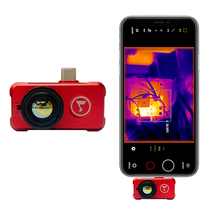
- ✅ 256x192 (49,152 pixels): This is what you find in entry-level hardware like common smartphone mini USB thermal accessories. It works okay for checking a breaker panel from a meter away, but try classifying a target at 30 meters and you’ll just see a blurry, pixelated blob.
- ✅ 384x288 (110,592 pixels): This has been the standard mid-range option for simple inspections. But it falls short when you pairing it with a wide lens; the field of view gets wide, but the spatial resolution drops, leaving you blind to small thermal anomalies.
- ✅ 640x512 (327,680 pixels): This is the professional standard. You get nearly 300% more raw pixels than a 384x288 array and a massive 660% increase over 256x192 sensors.
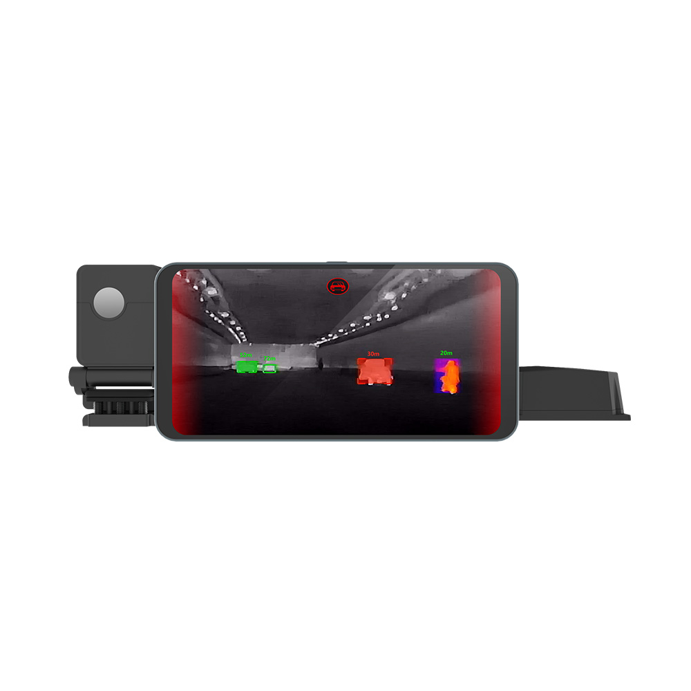
In the field, that resolution jump changes everything. First, it directly boosts your DRI (Detection, Recognition, Identification) ranges. Under the exact same optic, you can spot target signatures at triple the distance of 384-class cores. Second, you get a clean digital crop. If you crop a 640x512 frame by 2x, you still have a highly usable 320x256 image. Try that with a low-res 256x192 sensor, and you’re left with a pixelated 128x96 mess that’s useless for automated algorithms.
Finally, higher pixel density helps prevent thermal "bleeding." This happens when the heat signature of a small object (like a failing surface-mount resistor on a PCB) bleeds into adjacent pixels because the sensor’s spatial sampling can't resolve it. A native 640x512 sensor isolated to 12-micrometers cures this issue, containing the measurement to the exact component you're testing.

Uncooled Microbolometers: Thermal Physics and Material Selection
Uncooled microbolometers work by letting the infrared radiation do the physical heating. Each pixel is a tiny plates suspended over a silicon substrate on micromachined legs. This suspension isolates the pixel thermally, allowing it to heat up from the incoming infrared photons. A layer of thermistor material on the plate changes its electrical resistance as the temperature shifts, and this change is measured by the Read-Out Integrated Circuit (ROIC) underneath.
The materials game comes down to two choices:
- ⚙️ Vanadium Oxide (VOx): VOx is the premium choice for hardware. It provides a high Temperature Coefficient of Resistance (TCR), meaning its resistance shifts dramatically with even a tiny change in temperature. It also exhibits low 1/f (flicker) noise, which gives you a much better Noise Equivalent Temperature Difference (NETD). If your system has to work in freezing temperatures or heavy monsoon rains, VOx is the material you want.
- ⚙️ Amorphous Silicon (a-Si): This material is easier to integrate into standard silicon manufacturing lines, which keeps costs down. But a-Si typically suffers from higher noise levels and lower thermal sensitivity, making it prone to signal drift when the camera's housing warms up during operation.
By using VOx microbolometers with a tight 12-micrometer pixel pitch, modern high-resolution cores achieve an NETD of under 40mK (and often below 30mK in well-calibrated systems). In plain terms, the core can resolve temperature differences down to 0.03°C, giving you clean thermal transitions even in flat, low-contrast environments.
But the sensor is only half the battle. Regular optical glass blocks LWIR wavelengths entirely, so you can't use standard camera lenses. Instead, we use exotic materials like high-purity, single-crystal Germanium (Ge) or specialized chalcogenide molded-glass optics.
Top-tier optical manufacturers like LightPath Technologies design and coat these specialized lenses. They apply anti-reflective (AR) and Carbon-hardened coatings to ensure optical transmission exceeds 90% in the 8–14 μm band. This prevents reflections and distortion at the edges of the sensor, preserving detail across the entire 640x512 frame.
System Architectures: ASIC vs. FPGA Embedded Cores
When you're designing a custom build, the processing hardware inside the core will dictate your power budget, physical space, and startup speed. You'll have to choose between a Field Programmable Gate Array (FPGA) and an Application-Specific Integrated Circuit (ASIC).
Before making that choice, let’s look at what the processor actually does on the fly:
- Non-Uniformity Correction (NUC): Adjusts for manufacturing variations across all 327,680 individual pixels. It uses an internal physical shutter to block the sensor, taking a uniform temperature reading to recalibrate and level the pixel outputs (Flat Field Correction).
- Bad Pixel Replacement (BPR): Detects pixels that are dead or stuck hot and replaces their values by interpolating data from neighboring pixels in real time.
- Digital Detail Enhancement (DDE): Applies spatial filters to enhance fine lines and edges without boosting background noise.
- Automatic Gain Control (AGC): Compresses the raw 14-bit thermal data down to an 8-bit stream that displays and monitors can actually handle, using algorithms like Contrast Limited Adaptive Histogram Equalization (CLAHE).
Let's look at how the processing platforms handle these operations under different design constraints:
FPGA-Driven Cores
FPGAs give you lots of flexibility to load custom pixel-processing or target-tracking algorithms right onto the silicon. But they have some notable trade-offs in real-world environments:
Power Consumption: FPGAs are power hogs, often drawing between 1.5 to 3 Watts. On a drone payload, that extra draw eats into your flight time. It also generates considerable heat inside the housing, which can cause local sensor drift and force the system to trigger more frequent shutter recalibrations that momentarily freeze your video feed.
Boot Latency: FPGAs have to load a bitstream from memory on power-up. This can delay your startup by several seconds when you power on the system.
Size Profile: FPGAs require extra support chips, power rails, and decoupling capacitors, which swells the PCB footprint.
ASIC-Driven Cores
By hard-coding the image processing pipeline directly into microchips, ASIC-based thermal cores offer a highly optimized alternative:
Ultra-Low Power Draw: ASIC cores typically pull less than 0.8 Watts. This low power draw keeps the camera cool, preventing local heat buildup from affecting the sensor's calibration.
Near-Instantaneous Booting: Real-time operations begin within milliseconds of power application since there is no gate array configuration step.
Minimal Footprint: ASIC integration allows manufacturers to shrink the entire processing logic onto a single board, enabling miniature 21mm x 21mm form factors ideal for integration into standard handheld devices or small drone optical gimbals.
In-Depth Product Catalog & Technical Tables
To meet the needs of different projects, we manufacture two main 640x512 thermal camera models. Both offer professional uncooled performance but use different interfaces to fit into your system's communication pipeline.
Product 1: The Network/ASIC Sovereign Core
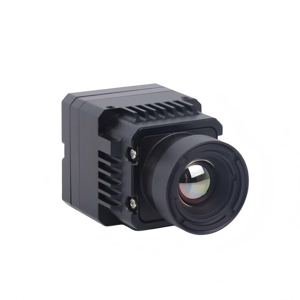
The Uncooled Infrared RJ45 CVBS RTSP IP 640*512 Thermal Sensor Camera Module is built for network-heavy security setups, long-range facility monitoring, and smart-city edge hardware. It features built-in Ethernet (RTSP/IP), dual-channel analog CVBS, and onboard ASIC processing, making it easy to plug directly into IP video setups.
This module also pairs well with specialized thermal spherical PTZ camera systems, acting as a high-resolution, long-range node in a multi-camera security layout.
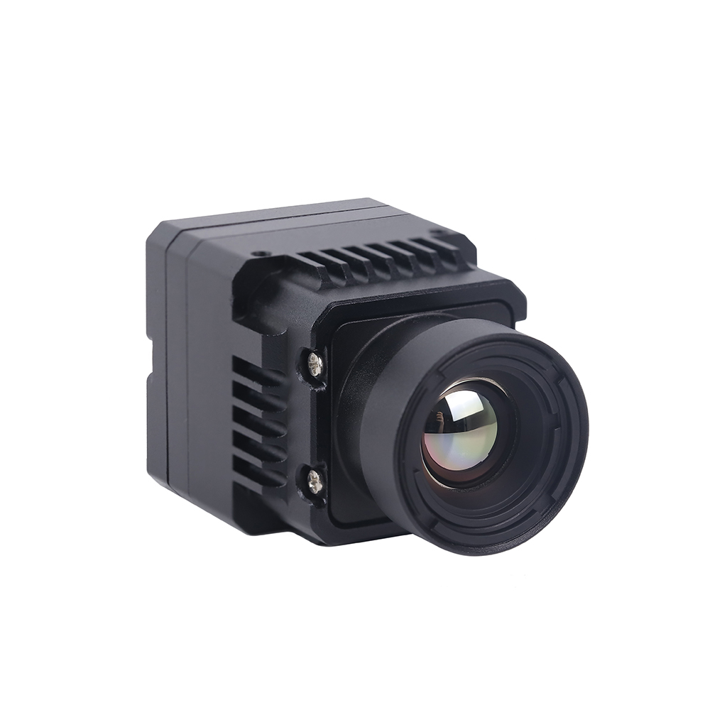
Figure 1: The RJ45 IP ASIC Thermal Camera Module featuring integrated networking.
View Product Details & Pricing ➔
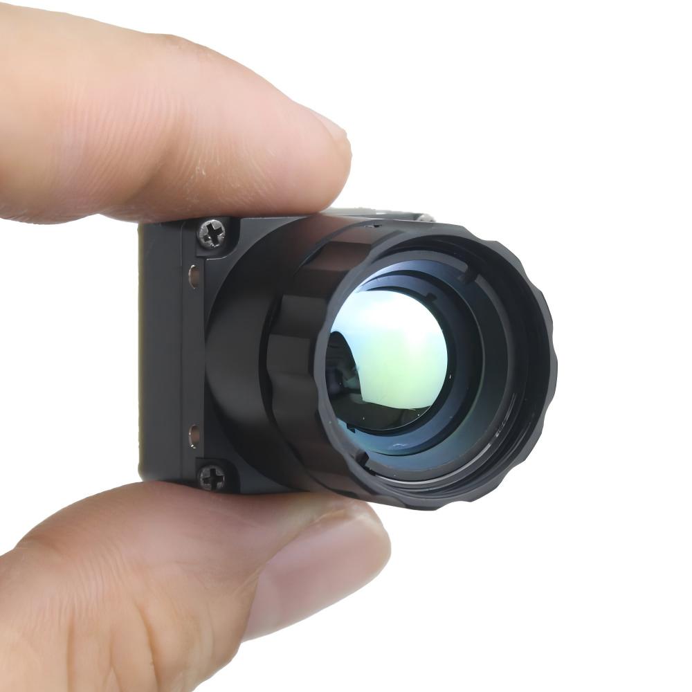
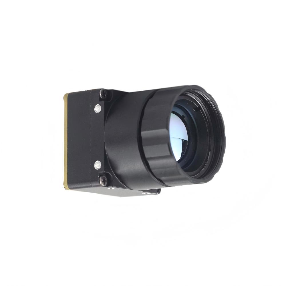
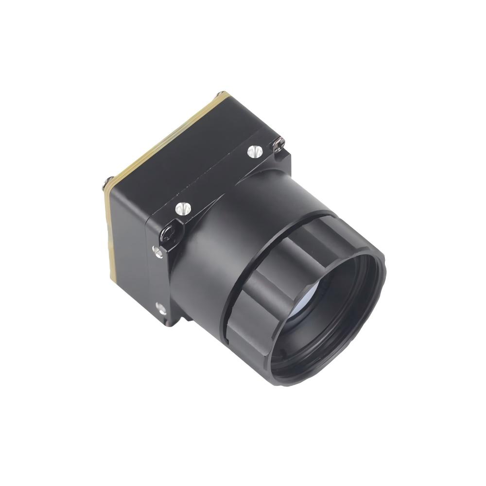
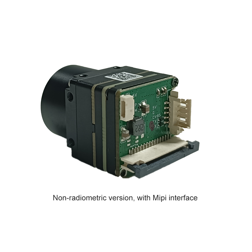
Product 2: The Ultra-Miniature SWaP Core
The Uncooled LWIR USB Mini 640*512 Thermal Imaging Camera Core Module For Drones Similar To DJI is optimized for low size, weight, power, and cost (SWaP-C). It packs a 640x512 array into a tiny 21mm x 21mm layout, using USB UVC output to interface directly with space-constrained drone gimbals and DIY SBCs.

Figure 2: The Mini 640 LWIR Thermal Core Module, displaying its ultra-compact form factor.
View Product Details & Pricing ➔
The table below provides a detailed technical comparison of these two high-resolution modules:
| Engineering Metric | RJ45 IP ASIC Module (640x512) | LWIR USB Mini Drone Core (640x480/512) |
|---|---|---|
| Sensor Resolution | Native 640 x 512 pixels | Native 640 x 512 (640x480 option available) |
| Detector Pitch & Material | 12 µm Vanadium Oxide (VOx) Microbolometer | 12 µm Vanadium Oxide (VOx) Microbolometer |
| Physical Dimensions | 28mm x 28mm (Main PCB Profile) | Ultra-miniature 21mm x 21mm footprint |
| Output Interfaces | RJ45 Ethernet (IP/RTSP) + Analog CVBS | USB UVC (OTG-Compliant) + Digital Parallel |
| Streaming Latency | ~120ms (over RTSP H.264/H.265 pipeline) | <30ms (uncompressed USB UVC raw direct video) |
| Power Consumption | < 1.2 Watts (during active stream, with peak shutter spikes) | < 0.7 Watts (steady state output) |
| Optics Support | Fixed thread options standard (9/13/19mm typical) | Threaded mount options: 5/9/13/18/35/50/75/100/150mm lenses |
| Software Configuration | Onboard Web GUI, ONVIF Profile S protocols | Direct USB UVC, serial command SDK controls |
| Primary Deployments | Security networks, perimeter defense, PTZ cameras | UAV Gimbal integration, thermal scopes, DIY PCB rigs |
Hardware Integration Blueprint: Interfaces, Drones, & Custom SBCs
When you're routing high-frequency serial lines, balancing power distributions, and designing gimbals, mechanical and electrical integration is where things get tricky. Getting a clean signal from a 640x512 LWIR core to a custom SBC or drone controller requires careful setup.
Interface Strategy: USB UVC vs. RJ45 IP
Your choice depends on how your hardware architecture handles video stream data:
- ✅ When using the RJ45 IP/ASIC Core: This module runs an internal, hardware-level Linux kernel that compresses raw frame structures into standard H.264/H.265 streams directly in real time. It's built for remote monitoring over long copper runs. You can pull the RTSP stream using standard players like VLC or video libraries like GStreamer. Compatibility with ONVIF means you can easily drop it into existing security networks.
- ✅ When using the Mini USB Core: This module runs as a standard UVC device. Plugging it into an SBC like a Raspberry Pi or an NVIDIA Jetson gives you immediate access to raw, uncompressed thermal frames. This makes it ideal for low-latency computer vision, edge AI detection, and close-range processing.
Coordinated Physical Integration with Hardware Platforms
To control the camera core or mix in other sensor data (like GPS coordinates or telemetry), you'll want to wire your control board to the core's serial lines.
If you're using the Arduino hardware ecosystem, you can connect the micro-serial RX/TX pins of the 640x512 core to your board's UART lines. This lets you send serial hex commands to trigger a NUC shutter calibration, switch digital color palettes, or pull specific pixel temperature data.
If you're on a platform like the Raspberry Pi running Linux, you can capture full-resolution raw video frames over the USB UVC connection for processing:
import cv2

# Initialize the Mini USB 640 thermal sensor as standard UVC input
cap = cv2.VideoCapture(0)

# Request the high-resolution uncompressed acquisition
cap.set(cv2.CAP_PROP_FRAME_WIDTH, 640)
cap.set(cv2.CAP_PROP_FRAME_HEIGHT, 512)

while True:
    ret, frame = cap.read()
    if not ret:
        break

    # Process the thermal frame (e.g., color map, spot-temperature tracking)
    # ...

    cv2.imshow('High-Res Thermal Pipeline', frame)
    if cv2.waitKey(1) & 0xFF == ord('q'):
        break

cap.release()
cv2.destroyAllWindows()
Key Considerations for Drone Deployment
If you are building a custom thermal camera payload for an inspection drone or an agricultural quadcopter, keep these three integration rules in mind:
- ⚙️ Thermal Isolation: Uncooled microbolometers are highly sensitive to rapid variations in temperature. If you mount your core right next to hot power distribution lines or speed controllers (ESCs), the thermal drift will mess up your calibration. Use thermal isolation mounts, dry carbon fiber plates, or air gaps to shield the core.
- ⚙️ RF Shielding: High-powered video transmitters and telemetry antennas can bleed RF interference into analog video lines or clean parallel buses, causing diagonal noise lines on your thermal feed. Run shielded coaxial lines, use twisted-pair wiring, and keep raw digital runs as short as possible.
- ⚙️ Inertial Balance: At 21mm x 21mm, the Mini USB core is lightweight, but pairing it with larger telephoto lenses (such as 75mm or 100mm optics) shifts the center of gravity forward. Make sure you mount the camera assembly at its physical balance point inside the gimbal to avoid burning out your stabilization motors.
Optical Engineering: Lens Selections (5mm to 150mm) and iFOV Calculations
A high-quality 640x512 core is only as good as the lens in front of it. Choosing the right focal length controls your field of view and determines how far away you can spot a target.
To evaluate performance, we calculate the Instantaneous Field of View (iFOV). This tells you the physical area on the ground representing a single pixel on the FPA:
iFOV = Pixel Pitch (µm) / Lens Focal Length (mm)
Let's look at how the math plays out with our 12-micrometer (0.012 mm) VOx cores across two different lens configurations:
Case A: Wide-Angle Optics (9.0 mm Focal Length)
Applying the formula:
iFOV = 12 µm / 9.0 mm = 1.33 milliradians (mrad)
At a distance of 100 meters, each pixel covers a physical square dimension of:
Dimension = 1.33 mrad × 100 m = 13.3 cm (per pixel)
Primary Application: Crop health mapping, short-range building air leak surveys, and wide-area industrial monitoring.
Case B: Long-Range Telephoto Optics (75.0 mm Focal Length)
Applying the formula:
iFOV = 12 µm / 75.0 mm = 0.16 milliradians (mrad)
At the same distance of 100 meters, each pixel covers a physical square dimension of:
Dimension = 0.16 mrad × 100 m = 1.6 cm (per pixel)
Primary Application: Inspections on high-voltage substation lines, long-range search and rescue, and perimeter security.
The math is clear: the telephoto lens concentrates your 640x512 resolution onto a much smaller spot, giving you highly detailed thermal readings and excellent target recognition at long ranges.
Engineering FAQ: Low-Latency Streaming, Sharpness, & DIY Porting
Question: What is the best interface pattern for real-time streaming to a micro-controller or low-power SBC?
For low-latency real-time streaming to low-power host boards, the **USB Mini 640 Core** using USB UVC is the ideal interface pattern. Because the UVC driver is baked into the Linux kernel of host boards like Raspberry Pi, BeagleBone, and Jetson, the thermal core is recognized immediately as a typical USB camera node (e.g., `/dev/video0`). This architecture bypasses custom frame grabbers and decoders. Alternatively, if your system operates within connected IP architectures of surveillance environments, the RJ45 IP ASIC module provides onboard H.264/H.265 compression. This compresses the raw video metadata stream and broadcasts it via RTSP/UDP protocols, allowing any connected edge network station to monitor the high-resolution thermal stream without demanding high processing power from the host computer.
Question: Why do cheap consumer thermal modules look blurry, and how do I guarantee true high resolution?
Many low-cost consumer thermal sensors display a blurry image because they pair low-resolution detector arrays (like 80x60 or 160x120) with cheap chalcogenide lens models and use soft digital interpolation to upscale the image block to standard display sizes. This upscaling duplicates adjacent pixels but cannot resolve actual fine details, masking critical temperature faults. True high resolution is achieved through three key hardware components: a genuine, native 640x512 uncooled VOx focal plane array; low sensor noise levels (NETD < 40mK or < 30mK) to distinguish faint thermal signals; and high-quality Germanium or chalcogenide glass optics that preserve edge contrast without geometric distortion.
Question: Can these uncooled cores be used in agricultural mapping drones and hand-held search units?
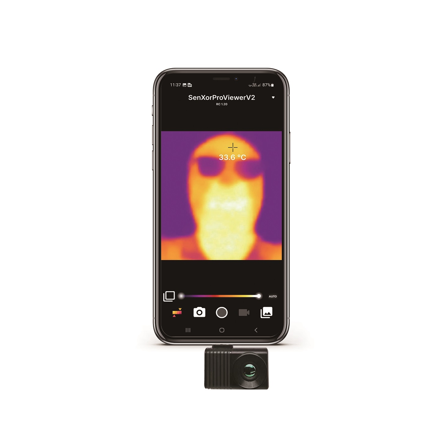
Absolutely. Both of these uncooled 640x512 core models are explicitly designed for lightweight payloads and mobile integrations. The Mini USB Core is particularly well-suited for agricultural mapping drones and custom search units, weighing just 15 grams (excluding optics) and measuring 21mm x 21mm. Operating on less than 0.7 Watts of power, it minimizes drain on aircraft batteries. For developers building handheld monoculars or thermal scopes, the serial SDK makes it straightforward to interface with small custom display screens and control buttons. This allows users to easily cycle through color palettes (such as Ironbow, Rainbow, White-Hot, and Black-Hot), configure high-voltage alarm overlays, run shutter calibrations, and record diagnostic data directly to an onboard SD card.
You can read more technical design comparisons and software execution methods in our dedicated uncategorized thermal technology updates archive.
📚 References & Further Reading
- Industry Standard: Microcontroller platform controls and driver integration methods on Arduino Development Hub
- Optical Engineering: High-transmission infrared Germanium and chalcogenide design principles at LightPath Technologies
- Related Guide: Comprehensive breakdown of hand-held mobile structures and Type-C temperature measurement systems
- Industrial Integration: Designing multi-sensor arrays and thermal spherical PTZ cameras for wide-area deployment
- Technical Archive: System integration manuals and uncategorized thermal technology updates
