Thermal Imaging Camera Guide: Real-World Testing, Resolution & OEM Cores
2026年10月15日
Thermal Imaging Camera Guide: Resolution, Sensor Specs & Core Modules Explained
2026年10月19日
Thermal Camera Guide: How to Choose, Integrate, and Maximize AI Infrared Performance
Modern industrial automation, predictive maintenance, and autonomous robotics require sensory capabilities that extend beyond the visible electromagnetic spectrum. While conventional optical vision systems fail in zero-lux environments, smoke, dust, and heavy atmospheric obscurants, uncooled long-wave infrared (LWIR) thermal camera systems capture the passive kinetic heat signatures emitted by any physical matter possessing a thermodynamic temperature above absolute zero (0 Kelvin). The modern thermal imaging landscape has transitioned from qualitative thermographic displays into quantitative microbolometer arrays integrated with specialized application-specific integrated circuits (ASICs). These advanced cores digitize raw radiometric flux at the focal plane, performing on-chip non-uniformity correction and feeding multi-spectral machine learning pipelines in real time.
Deploying a high-performance thermal camera into an industrial, aerospace, or original equipment manufacturer (OEM) assembly demands a comprehensive understanding of optoelectronic trade-offs. Systems engineers must navigate complex design variables: selecting between Vanadium Oxide (VOx) and Amorphous Silicon (a-Si) sensor chemistries, calculating Instantaneous Field of View (iFOV) against Johnson's criteria, optimizing Noise Equivalent Temperature Difference (NETD) under varying aperture ratios, and routing 14-bit radiometric data through low-latency embedded digital pipelines like MIPI-CSI or RTSP IP streams. This comprehensive technical guide details the underlying physics, optical considerations, hardware interfaces, edge AI integration protocols, and OEM hardware profiles necessary to build reliable, high-accuracy infrared sensing platforms.
Table of Contents
- 👉 1. Sensor Physics and Microbolometer Architecture
- 👉 2. Key Engineering Selection Criteria for Industrial & Aerial Systems
- 👉 3. Edge AI Vision Pipelines & Interface Architectures
- 👉 4. Industrial OEM Product Specifications & Architectural Teardown
- 👉 5. High-Impact Industrial Deployments & Field Engineering
- 👉 6. Deep-Dive Technical FAQ
1. Sensor Physics and Microbolometer Architecture
Every thermal camera functions by converting incident radiative flux into an interpretable electrical signal. The physics governing this conversion relies on the foundational principles of quantum mechanics and thermodynamics. Planck’s Radiation Law defines the spectral radiance emitted by an idealized blackbody at a given thermodynamic temperature across varying wavelengths. Integrating Planck's distribution across all wavelengths yields the Stefan-Boltzmann Law, which establishes that total radiant emittance is directly proportional to the fourth power of the emitter's absolute temperature: W = εσT4, where ε is the material's surface emissivity, σ represents the Stefan-Boltzmann constant (5.670374 × 10⁻⁸ W/m2K4), and T is absolute temperature in Kelvin.
Furthermore, Wien’s Displacement Law demonstrates that as an object's temperature increases, the peak wavelength of its emitted radiation shifts inversely according to λmax = b / T, where b is Wien's displacement constant (≈ 2897.8 µm·K). For terrestrial objects operating within standard ambient and industrial temperature envelopes (-40°C to +500°C, or 233 K to 773 K), the peak spectral radiance resides precisely within the Long-Wave Infrared (LWIR) atmospheric transmission window, which extends from 8 µm to 14 µm. In this spectral band, atmospheric attenuation caused by water vapor and carbon dioxide absorption is minimal, allowing accurate standoff thermal measurements across expansive outdoor and factory facilities.
1.1 The Radiometric Conversion Pipeline
The core component of an uncooled thermal camera is the Focal Plane Array (FPA) consisting of microbolometers. Unlike cooled photon detectors (such as Indium Antimonide or Mercury Cadmium Telluride) that require bulky Stirling cryogenic coolers operating at 77 Kelvin, an uncooled microbolometer operates at room temperature. Each individual microbolometer pixel consists of an infrared absorption membrane suspended above a silicon substrate by micro-machined support legs. These legs create a high degree of thermal isolation within an evacuated, hermetically sealed cavity under high vacuum, often maintained over operational lifetimes by integrated chemical getter materials.
When incident LWIR photons pass through a specialized antireflective-coated Germanium lens, they strike the suspended membrane. The absorbed radiant flux elevates the microbolometer's internal temperature, which directly alters the electrical resistance of the material. A Readout Integrated Circuit (ROIC), bonded directly beneath the pixel array, periodically samples this resistance change by applying a constant bias voltage or current. The resultant analog voltage shifts are transferred via multiplexed column amplifiers to on-chip high-speed Analog-to-Digital Converters (ADCs), which generate a 14-bit or 16-bit raw digital count per pixel.
Translating these raw digital counts into precise temperature values requires solving the complete radiometric equation inside the camera processor:
Wtotal = ε · τatm · Wobj(Tobj) + (1 - ε) · τatm · Wamb(Trefl) + (1 - τatm) · Watm(Tatm)
In this formulation, the total power Wtotal absorbed by the sensor includes the target's emitted energy attenuated by atmospheric transmittance (τatm), the ambient background thermal flux reflected by the target's non-blackbody surface, and the radiation emitted directly by the intervening atmosphere. Detailed examinations of this readout mechanism can be explored within our VOx uncooled thermal imaging module buying guide, which illustrates how contemporary ROIC architectures manage offset drifts and bias stabilization.
1.2 VOx vs. Amorphous Silicon (a-Si) Detector Materials
The active thermistor layer deposited on the microbolometer membrane fundamentally dictates the detector's operational characteristics. The global thermal imaging sector relies on two primary materials: Vanadium Oxide (VOx) and Amorphous Silicon (a-Si).
| Evaluation Metric | Vanadium Oxide (VOx) | Amorphous Silicon (a-Si) |
|---|---|---|
| Temperature Coefficient of Resistance (TCR) | High (≈ 2.0% to 3.0% / K) | Moderate (≈ 1.5% to 2.5% / K) |
| 1/f Electronic Noise | Significantly lower intrinsic flicker noise | Higher 1/f noise due to disordered atomic structure |
| Thermal Time Constant (τ) | Fast response (8 ms to 12 ms) | Slower response (12 ms to 16 ms) |
| Manufacturing Processing | Dedicated MEMS cleanrooms, precise phase control | Standard silicon CMOS foundry compatibility |
| Thermal Sensitivity (NETD) | Superior: frequently < 30 mK to 40 mK | Standard: typically 50 mK to 70 mK |
VOx is the preferred material for mission-critical industrial inspection, surveillance, and dynamic aerial robotics. Its elevated TCR ensures that even an infinitesimal change in target surface temperature produces a measurable shift in electrical resistance. Coupled with a low 1/f flicker noise profile, VOx sensors achieve high Signal-to-Noise Ratios (SNR) without aggressive temporal filtering, preventing ghosting artifacts when panning across complex industrial environments. In contrast, while Amorphous Silicon enables lower-cost wafer manufacturing by leveraging traditional silicon fabs, its higher noise floor and slower thermal dissipation make it less suitable for high-speed edge AI vision or precision aerial mapping.
1.3 Thermal Sensitivity (NETD) and Optical Aperture Dynamics
The primary figure of merit for any thermal camera is its Noise Equivalent Temperature Difference (NETD), expressed in millikelvins (mK). NETD represents the temperature differential that yields a signal equal to the RMS noise of the system. A lower NETD indicates superior sensitivity, allowing the sensor to resolve subtle thermal anomalies against uniform backgrounds:
- ✅ < 30 mK to 40 mK: High-performance standard. Resolves micro-fractures in composite structures, early fluid ingress in wind turbine blades, and fine insulation degradation.
- ⚙️ 50 mK to 60 mK: Mid-tier industrial performance. Capable of locating tripped breakers, mechanical pump over-temperatures, and large plumbing leaks.
- ⚠️ ≥ 80 mK: Entry-level performance. Suitable only for basic presence detection and coarse thermal thresholding.
Importantly, NETD is an integrated system metric that depends on the optical assembly's f-number (f/#). Thermal sensitivity degrades inversely with the square of the lens aperture:
NETDsystem ∝ (f/#)2
A sensor that achieves an NETD of 40 mK when paired with an expansive f/1.0 aperture lens will see its sensitivity degrade to 90 mK if mated to an f/1.5 optic, obscuring low-contrast thermal features. Furthermore, standard optical glass absorbs LWIR energy; thermal cameras require high-purity monocrystalline Germanium (Ge) or specialized Chalcogenide glass elements. These optics feature broadband antireflective (BBAR) coatings that maximize transmission above 90% across the 8 µm to 14 µm spectrum while protecting the substrate from corrosive industrial atmospheres.
2. Key Engineering Selection Criteria for Industrial & Aerial Systems
Selecting an infrared engine for machine vision, uncrewed aerial vehicles (UAVs), or automated factory infrastructure requires balancing spatial resolving power, mechanical constraints, and communication architectures against performance targets.
2.1 Spatial Resolution, iFOV, and Johnson's Criteria
Spatial resolving power determines the maximum operating distance for detection and measurement. The primary parameter is the Instantaneous Field of View (iFOV), which defines the angle subtended by a single physical pixel through the optical center:
iFOV = Pixel Pitch (p) / Focal Length (f)
When selecting a contemporary sensor with a 12 µm (0.012 mm) pixel pitch coupled to a 19 mm Germanium lens, the mathematical calculation yields:
iFOV = 0.012 mm / 19 mm = 0.6315 milliradians (mrad)
At an aerial inspection altitude of 100 meters, a single pixel covers a footprint on the ground calculated as:
Ground Projected Footprint = Distance × iFOV = 100 m × 0.0006315 rad = 0.0631 m (6.31 cm)
However, optical physics dictates that reliable radiometry (accurate temperature measurement) requires more than one single pixel. While detection can occur on a 1×1 pixel footprint, overcoming optical blur (Point Spread Function) and achieving radiometric accuracy requires a Measurement Instantaneous Field of View (MFOV) spanning at least a 3×3 or 4×4 pixel array covering the critical target dimension.
System designers validate their optical parameters using Johnson’s Criteria, which defines the line pairs required across an object's minimum critical dimension to achieve three perceptual tiers:
- 🔍 Detection (1.5 line pairs / ≈ 3 pixels): An object is distinguished from the thermal background (e.g., an anomaly is present on a high-voltage transmission tower).
- ⚙️ Recognition (6 line pairs / ≈ 12 pixels): The type of object can be classified (e.g., distinguishing an insulator stack from a transformer bushing).
- 🎯 Identification (12 line pairs / ≈ 24 pixels): Specific structural details are resolved (e.g., diagnosing failure on a single phase-disconnect crimp terminal).
Upgrading from an entry-level 384×288 array to an industrial 640×512 array yields a 2.96× increase in pixel density, expanding the standoff distance by nearly 70% under identical optical fields of view.
2.2 Frame Rates, Export Controls, and Motion Blur
Thermal camera systems operate across two broad frame rate categories, largely dictated by international arms and dual-use export regulations (such as the US ITAR framework and European Dual-Use regulations):
- ⚙️ ≤ 9 Hz (Slow-Motion) Systems: These modules fall outside strict export licensing regimes and can be shipped globally with minimal regulatory overhead. However, 9 Hz systems introduce temporal latency and motion blur. In high-speed inspection lines or dynamic drone gimbals, a 9 Hz refresh rate causes pixel smearing, invalidating automated edge AI bounding-box tracking.
- ✅ 25 Hz / 30 Hz / 50 Hz / 60 Hz Systems: Essential for aerial inspection, automated guided vehicles (AGVs), perimeter robotics, and industrial process automation. High frame rates provide the temporal fidelity needed for non-uniformity correction shutters to actuate without freezing the video pipeline, while preventing spatial distortion during platform movement. Procuring high-rate cores requires appropriate export paperwork and verified supply chains through authorized global distribution partners like OBSETECH.
2.3 SWaP-C Constraints in Robotics and Aerial Platforms
For uncrewed systems, the SWaP-C (Size, Weight, Power, and Cost) envelope directly determines mission viability. Aerial camera payloads must minimize mechanical and electrical impact:
- ⚙️ Mass Optimization: Every additional 10 grams on a 3-axis brushless gimbal demands larger stabilization motors, increasing current draw and reducing flight endurance. Modern miniature thermal cores must weigh under 40 grams to integrate seamlessly into lightweight payloads.
- ⚙️ Parasitic Thermal Dissipation: Microbolometers are sensitive to ambient thermal gradients. A thermal core consuming > 2.5 W dissipates parasitic heat that can transfer directly into the sensor mounting bracket, generating thermal drift across the FPA. Low-power cores consuming ≤ 1.2 W preserve UAV battery life and minimize internal thermal blooming, maintaining calibration accuracy.
3. Edge AI Vision Pipelines & Interface Architectures
Modern machine vision systems treat the thermal camera not merely as an analog display device, but as an intelligent, high-bandwidth edge-sensing node. Ingesting radiometric feeds into edge AI compute platforms (such as the NVIDIA Jetson Orin series or Rockchip RK3588) requires an optimized digital interface architecture.
3.1 Hardware Interfaces: MIPI-CSI, USB UVC, Ethernet RTSP, and CVBS
Connecting an infrared core to an edge processor depends on physical distance, processing topology, and latency budgets:
- ⚙️ MIPI-CSI-2 (Camera Serial Interface): The preferred interface for embedded OEM systems. It links the camera's ROIC/ASIC directly to the host processor’s hardware Image Signal Processor (ISP), bypassing peripheral bridge chips. It delivers uncompressed 14-bit radiometric frames with near-zero latency, but trace lengths are limited to approximately 15 to 20 cm without active redrivers.
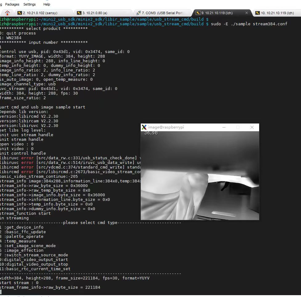
- ⚙️ USB UVC (Universal Video Class): Offers simple plug-and-play integration for embedded Linux and Windows systems. It operates across standard V4L2 drivers, streaming 8-bit AGC video alongside interleaved 14-bit radiometric metadata arrays directly into OpenCV architectures.
- ⚙️ Ethernet IP (RTSP / ONVIF): The standard for factory automation, SCADA facilities, and perimeter surveillance. On-chip ASICs encode video into H.264/H.265 streams transmitted via an RJ45 connection over distances up to 100 meters. For a deeper breakdown of multi-camera Ethernet networks, explore our technical guide on commercial infrared thermal imaging solutions.
- ⚙️ CVBS (Composite Video Baseband Signal): An analog standard operating over a single 75-ohm coaxial lead. CVBS remains widely used in FPV drone gimbals and legacy avionics due to its zero-latency analog transmission and immunity to operating system lockups.
3.2 Radiometric Raw 14-Bit vs. 8-Bit Grayscale Ingestion
A common engineering error in AI thermal vision integration is feeding 8-bit compressed streams directly into convolutional neural networks. An 8-bit stream compresses high-dynamic-range scenes into 256 discrete values via an Automatic Gain Control (AGC) or Contrast Limited Adaptive Histogram Equalization (CLAHE) algorithm. In doing so, all absolute temperature calibration data is stripped away. An object may appear visually distinct, but its pixel value changes dynamically depending on what else enters the field of view.
High-reliability AI safety systems instead ingest the uncompressed raw 14-bit radiometric feed (16,384 discrete levels), where each pixel represents a calibrated digital count that maps directly to absolute temperature. The processing pipeline bifurcates at the edge compute node:
- 🔍 The Radiometric Channel: The edge SoC applies an absolute threshold mask directly to the 14-bit data (e.g., isolating all pixels exhibiting temperatures > 85°C). This arithmetic filtering instantly flags overheating components, eliminating false positives caused by ambient solar reflections.
- 🎯 The Visual Channel: The 14-bit array is normalized into an 8-bit spatial image to drive object detection models (such as YOLOv8, RT-DETR, or Faster R-CNN) running on INT8-quantized TensorRT runtimes. This dual-pipeline architecture combines visual object recognition with absolute radiometric safety boundaries.
3.3 On-Chip ASIC Processing, NUC, and Shutter Calibration
Microbolometer arrays are susceptible to spatial non-uniformities caused by manufacturing variances across pixel bridges and thermal drift from the camera's housing. This appears as Fixed Pattern Noise (FPN), resembling a textured grid over the image. Modern thermal cameras resolve this drift via dedicated hardware engines:
- ⚙️ Non-Uniformity Correction (NUC): An internal mechanical solenoid briefly places an isothermal shutter blade in front of the FPA, presenting all pixels with a uniform temperature field. The ASIC recalculates offset coefficients for each individual pixel, subtracting the FPN pattern. Advanced cores deploy shutterless continuous algorithms that continuously estimate and remove spatial noise using scene motion dynamics.
- ⚙️ Bad Pixel Replacement (BPR): Pixels exhibiting non-responsive resistance or excessive 1/f noise are flagged during factory calibration. The ASIC automatically replaces these defective pixels using spatial polynomial interpolation from adjacent functional detectors.
- ⚙️ Digital Detail Enhancement (DDE): Advanced spatial filtering divides the thermal image into low-frequency data (broad temperature fields) and high-frequency data (fine structural edges). The ASIC amplifies the high-frequency band, making thin pipes, hairline cracks, and structural framing stand out clearly without blowing out the dynamic range.
4. Industrial OEM Product Specifications & Architectural Teardown
Selecting the proper thermal camera hardware requires matching real-world mechanical, electrical, and optical needs against factory-calibrated core architectures. Below, we break down two industrial-grade uncooled LWIR OEM modules engineered for aerial payloads, robotics, and industrial condition monitoring.
Uncooled Mini 384×288 Thermal Camera Module For Drones
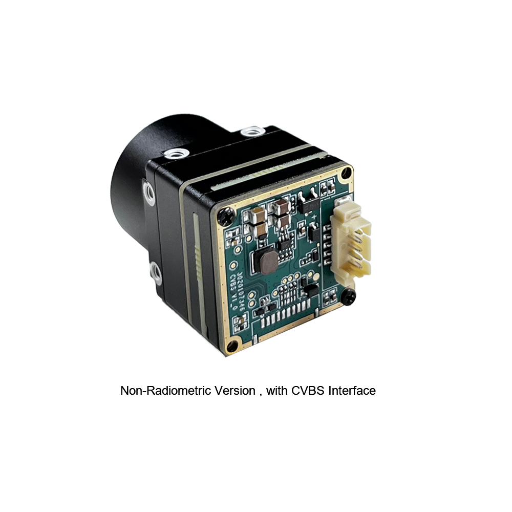
The MINI series infrared thermal imaging temperature measurement module is an ultra-compact, high-precision online thermal imaging core designed for tight payload applications. Built around a sensitive uncooled VOx detector array, it delivers reliable thermal resolution with minimal power draw. Equipped with multiple industrial interfaces, it serves as an adaptable thermal engine for machine vision, safety inspection, intelligent manufacturing, predictive plant maintenance, and lightweight drone/robotics payloads.
| Resolution Array | 384 × 288 pixels |
| Sensor Technology | Uncooled Vanadium Oxide (VOx) Microbolometer |
| Pixel Pitch | 12 µm |
| Spectral Band | 8 µm to 14 µm (LWIR) |
| Primary Interfaces | CVBS Analog, Serial Communication / Multi-interface configurations |
| Deployment Niches | Robotics, aerial UAS payloads, machine vision inspection, factory QA |
Uncooled Infrared RJ45 CVBS RTSP IP 640×512 Thermal Sensor Camera Module
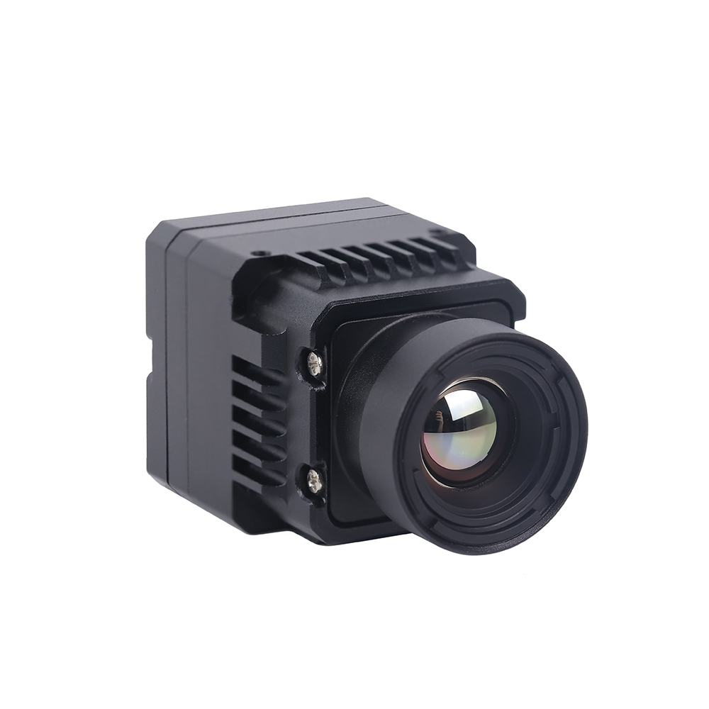
The Uncooled Infrared Mini 640×512 ASIC Thermal Imaging Camera Module is a high-resolution, networked sensor core built for advanced drone gimbals and continuous industrial surveillance. Featuring an onboard hardware ASIC processing engine, this module simultaneously handles low-latency CVBS analog output and digital H.264/H.265 RTSP IP streams via standard RJ45 Ethernet. Designed for automated tracking and wide-area industrial monitoring, it delivers detailed thermal imaging along with embedded network management protocols.
| Resolution Array | 640 × 512 pixels |
| Processor Core | Dedicated On-Chip ASIC Processing Engine |
| Sensor Technology | Uncooled VOx Infrared Microbolometer |
| Network Protocol | RJ45 Ethernet (RTSP / IP Video Streaming / ONVIF compliant) |
| Concurrent Video | Dual Pipeline: Digital IP Stream + Direct CVBS Analog |
| Primary Applications | Aerial inspection, fixed infrastructure fire prevention, industrial perimeter security |
4.1 Architectural Engineering Analysis of the Core Modules
Comparing these two modules highlights different integration philosophies across industrial system designs:
The Mini 384×288 Core is optimized for low Size, Weight, and Power (SWaP) applications. Drawing under 1.2 W, it integrates easily into balanced, multi-axis micro-gimbals on compact drones and quadruped robots. Its direct CVBS output bypasses software encoding, delivering zero-latency analog video directly to analog flight transmitters or secondary video monitors. The 384×288 resolution strikes an effective balance between resolving power and pricing, easily meeting Johnson’s Recognition Criteria for utility assets at standard low-altitude flight profiles (15 to 40 meters).
The 640×512 ASIC RJ45 Module, on the other hand, is built for high-resolution edge computing and multi-node networked environments. Its 640×512 array delivers nearly three times the spatial pixel density of 384×288 cores, allowing safe standoff inspection of high-voltage transmission lines, substation bushings, and distant chemical storage tanks. Crucially, the onboard hardware ASIC handles H.264/H.265 compression directly on the module, streaming RTSP video over standard Ethernet into factory SCADA platforms or Network Video Recorders (NVRs) without taxing the host computer. Sourcing these specialized ASIC camera modules for production runs can be coordinated through established international volume suppliers like KUYANG.
5. High-Impact Industrial Deployments & Field Engineering
Deploying a thermal camera in real-world industrial environments requires tailoring the physical mounting, spectral filtering, and software thresholds to the target operational context.
5.1 Drone & Aerial Asset Inspections
Mounting uncooled LWIR cameras on uncrewed aerial platforms provides rapid coverage of distributed utility assets:
- ✅ Solar Photovoltaic (PV) Plant Audits: In solar parks, localized anomalies such as cracked glass, internal cell delamination, or bypassed diodes force affected silicon cells into reverse bias. These defective cells cease generating electricity and instead dissipate power as heat, creating "hotspots" that can exceed surrounding temperatures by 20°C to 50°C. Aerial inspection systems running autonomous pathing and thermal AI engines detect these thermal signatures across thousands of panels in minutes, streamlining preventative maintenance.
- ✅ High-Voltage Transmission Grids: Loose crimp lugs, broken strand splices, and corroded disconnect switches introduce localized electrical resistance. Under heavy grid current (I), resistive heating increases rapidly (P = I2R). Aerial thermal imaging identifies these overheating connections from safe standoff distances, helping utilities prevent phase-to-ground flashovers and avoid unplanned grid outages.
For more architectural perspectives on autonomous inspection systems, review our technical compendium on industrial sensor deployment archives.
5.2 Fixed Continuous Thermal Surveillance & Fire Detection
Traditional optical cameras and smoke detectors often alert too late during industrial fires. Fixed-mount thermal cameras running automated RTSP edge analytics provide early warning by monitoring thermal buildup directly:
- ⚙️ Battery Energy Storage Systems (BESS): Lithium-ion battery fires are preceded by thermal runaway, which starts with microscopic internal dendrite shorts or venting degradation that elevates cell temperatures well before smoke appears. Fixed 640×512 thermal cameras continuously monitor battery rack surfaces, issuing automated shutoff triggers the moment temperatures exceed safety limits (e.g., > 60°C).
- ⚙️ Bulk Material Storage & Waste Management: Subsurface biological decomposition and exothermic chemical reactions within coal bunkers, municipal scrap yards, and woodchip silos often spark deep, hidden fires. Radiometric cameras continuously monitor these piles, locating hot spots beneath the surface layers before catastrophic fires break out.
5.3 Predictive Industrial Automation & Machine Vision QA
In high-speed production environments, thermal imaging provides automated quality control without physical contact:
- ⚙️ Injection Molding and Automotive Die Stamping: Non-uniform temperature distribution across an injection mold core leads to internal stresses, shrinkage, and premature part warping. Installing thermal cameras directly on machine frames allows automated inspection systems to map temperature gradients across parts as they eject, verifying thermal balance and rejecting defective pieces instantly.
- ⚙️ High-Speed Bearing and Mechanical Drive Monitoring: Industrial motors, large gearboxes, and centrifugal pumps generate friction heat when bearings degrade, races pit, or lubrication fails. Continuous radiometric thermal monitoring flags subtle friction heating over baseline trends, alerting maintenance teams to schedule service before catastrophic bearing seizures stop production lines.
6. Deep-Dive Technical FAQ
Are budget thermal cameras under $400 suitable for commercial electrical and industrial diagnostics?
How does a thermal camera calculate true temperature, and why is surface emissivity critical?
How can I stream real-time radiometric thermal video directly to a Raspberry Pi or NVIDIA Jetson?
What causes the periodic clicking sound and brief image freeze in thermal camera modules?
📚 References & Further Reading
- Industry Standard: Sourcing high-grade industrial cores and verified production supply lines through KUYANG Industrial Sourcing.
- Industry Standard: Export-compliant aerial drone thermal platforms and flight integrations via OBSETECH Flight Platforms.
- Related Guide: Explore deep architectural insights on microbolometers in our VOx Uncooled Thermal Module Integration Blueprint.
- Related Guide: Review deployment strategies for high-throughput factory lines in our Commercial Infrared High-Resolution Architecture Solutions.
- Related Guide: Examine multi-spectral and industrial robotics field deployments in our Industrial Sensor and Multi-Spectral Implementation Series.