Wholesale Thermal Camera Module: High-Performance LWIR Sensor Cores for OEM & Drones
2026年9月9日
Top Uncooled LWIR Thermal Camera Core Supplier | 640 & 1280 OEM Modules
2026年9月10日
Thermal Imaging Sensor Integration Guide: OEM Cores & Edge AI Vision
Modern autonomous platforms, tactical defense gear, and rugged factory systems need eyes that see well past the visual spectrum. Tossing a Long-Wave Infrared (LWIR) sensor into an embedded edge rig is a completely different ballgame compared to standard visible imaging. Standard RGB sensors count photons reflecting off a surface. Uncooled LWIR microbolometers do something entirely different: they pick up pure thermal radiation leaking out in the 8 to 14 µm atmospheric window. But shoehorning an OEM thermal core into a tight SWaP budget (Size, Weight, Power, and Cost)—think search drones, warehouse AGVs, and field IoT monitors—throws serious electro-optical, thermal, and algorithmic headaches your way. You can't just slap a thermal core onto a USB port and pretend it's a standard webcam. It's a precision, analog-to-digital radiometer that goes wild if ambient temperatures shift, drifts over time, and battles optical vignetting constantly.
Here's the deal: getting low-latency, rock-solid output means building an end-to-end plan covering physical PCB routing, picking the right bus (MIPI CSI-2 vs. USB 3.0), handling Non-Uniformity Correction (NUC), and pulling clean radiometric figures right at the edge. By pairing micro-pitch Vanadium Oxide (VOx) focal plane arrays with modern embedded System-on-Chips (SoCs)—like the NVIDIA Jetson Orin, NXP i.MX8, or dedicated edge NPUs—you can pull off real-time multispectral fusion, automatic flaw detection, and long-range human or vehicle classification straight through total darkness, heavy dust, or driving rain. This blueprint lays out the entire engineering roadmap, from down-and-dirty board layout to edge AI inference.
Table of Contents
- 👉 1. OEM LWIR Sensor Physics & Sensor Selection Criteria
- 👉 2. Electro-Mechanical Integration & SWaP-C Optimization
- 👉 3. Electrical Interfaces & Low-Latency Data Protocols
- 👉 4. Radiometric Calibration, NUC, and Shutterless Operation
- 👉 5. Edge AI Vision Pipelines & Multispectral Image Processing
- 👉 6. Purpleriver OEM LWIR Product Comparison Showcase
- 👉 7. Frequently Asked Questions (Deep-Dive Technical FAQ)
1. OEM LWIR Sensor Physics & Sensor Selection Criteria
Making a thermal core work comes down to understanding the physics running inside that uncooled Focal Plane Array (FPA). Visible CMOS sensors use the photoelectric effect to bounce valence electrons across a silicon bandgap into the conduction band. Thermal sensors don't work like that at all. In the 8 to 14 µm band, these detectors act as microscopic heat sponges. A microbolometer is essentially an isolated resistor membrane suspended over a reflective silicon floor by tiny, micromachined legs. Incoming long-wave radiation heats that suspended membrane, shifting its electrical resistance based directly on how hot the target is. The Read-Out Integrated Circuit (ROIC) applies a pulsed bias voltage or current across the structure, measures the tiny resistance shift, and converts those micro-Kelvin changes into digital numbers (DN) through fast, on-die ADCs.
1.1 VOx vs. a-Si Microbolometers: Thermal Sensitivity & Drift
In the shop, your first real crossroad is picking the active thermistor chemistry: Vanadium Oxide (VOx) versus Amorphous Silicon (a-Si). This choice decides your raw sensitivity, your 1/f noise floor, your manufacturing yield, and how much you have to fight thermal drift out in the field.
Vanadium Oxide (VOx): Look, VOx thin films are the hands-down standard for tactical defense, aerospace, and high-reliability industrial pods. VOx packs a high Temperature Coefficient of Resistance (TCR), sitting right around −2%/K to −3%/K at room temp (300 K). That responsiveness lets VOx focal plane arrays hit killer Noise Equivalent Temperature Difference (NETD) numbers, often dropping below 30 mK to 40 mK with an f/1.0 lens. A lower NETD means you resolve tiny temperature gradations, translating directly into razor-sharp object outlines and strong signal-to-noise ratios (SNR) in low-contrast muck—like sticky summer nights, open sea operations, or flat overcast fields. On top of that, VOx has significantly less 1/f flicker noise than amorphous silicon, keeping your baseline drift under control over long shifts.
Amorphous Silicon (a-Si): The big upside to amorphous silicon is fab compatibility. Because you can drop a-Si using standard, high-volume silicon CMOS lines, it has traditionally saved cash on wafer runs. But you take a hit: a-Si yields a weaker TCR (roughly −1.5%/K to −2.2%/K) and higher inherent 1/f noise from its messy atomic matrix. Because of that, a-Si cores regularly run higher NETD numbers (≥ 50 mK at f/1.0). If you have scenes with almost zero thermal variation, the output turns into a snowstorm unless you dial in brutal temporal filtering, which ruins your frame-to-frame clarity when tracking fast targets.
1.2 Resolution Scaling: From 32×24 Array Sensors to 640×512 and 1280×1024 FPAs
Low-end thermopile arrays (32×24 or 80×60) and budget microbolometers (160×120) do fine for basic occupancy sensing or spotting a blown motor bearing. But for edge AI target extraction, long-range aerial tracking, or high-end metrology, you need real pixel density: 640×512 (VGA-class) or 1280×1024 (HD-class) arrays.
Resolution dictates your spatial frequency on the focal plane, ruled by Johnson's Criteria for Detection, Recognition, and Identification (DRI). To catch a blip on screen, the glass needs to project at least 1.5 line pairs over the target's critical profile. Spotting what type of object it is (recognition) demands 6 line pairs; pinpointing exactly what it is (identification) takes 12 line pairs. The math governing how many raw pixels land on that target is simple:
Pixels on Target = (Target Dimension [m] × Focal Length [mm]) / (Distance to Target [m] × Pixel Pitch [µm])
Say you're running a perimeter drone looking for a human intruder (critical width: 0.75 m) standing 800 meters out, viewed through a 25 mm lens:
- ⚙️ Legacy 17 µm 320×256 FPA: The human paints across roughly 1.37 pixels. You can't even guarantee detection here; an edge AI network has zero shot at classifying that tiny smear.
- ⚙️ Modern 12 µm 640×512 FPA: The human hits roughly 3.90 pixels. You comfortably hit detection and enter the ballpark for basic class tagging.
- ⚙️ High-Density 12 µm 1280×1024 FPA: The target covers 7.81 pixels. Now your vision pipeline has the local gradient density that architectures like YOLOv8 or RT-DETR require to lock down confidence scores.
When you compress pixel pitches down from 17 µm to 12 µm or 8 µm, the surface area of each tiny microbolometer plate drops off a cliff. A 12 µm pixel collects barely half the radiant energy of a 17 µm pixel. To prevent the NETD from blowing out, sensor designers push fill factors past 85%, fine-tune optical resonant cavities, and pack ultra-low-noise integrator stages directly into the readout silicon.
Engineers scouting production-ready options can evaluate several configurations in the Purpleriver Product Catalog, which maps out form factors, pixel pitches, and base resolutions.
1.3 Optical Train Engineering: Germanium, Chalcogenide, and f-Number Impacts
LWIR optics have zero in common with visible glass. Standard optical crown or flint glasses like BK7 or fused silica act like solid brick walls to 8–14 µm light, swallowing thermal photons in the first few microns of material. That means thermal setups rely on exotic infrared elements:
Monocrystalline Germanium (Ge): Germanium is the heavy hitter for tactical LWIR glass. It offers a massive refractive index (n ≈ 4.003 at 10.6 µm), meaning lens designers can keep elements thin, curb spherical distortions, and run flatter curves. The catch? It has a brutal thermal refractive index shift (dn/dT ≈ 3.96 × 10⁻⁴ / °C), so it defocuses rapidly as ambient temps swing. Run it past 100 °C and free-carrier absorption takes over, causing thermal runaway that blacks out the optic completely.
Chalcogenide Glasses (e.g., GASIR, BD6): Chalcogenide materials (compounds of sulfur, selenium, tellurium, and other group-16 elements) solve several Germanium headaches. Refraction sits lower (n ≈ 2.5 to 2.8), but the thermal index drift (dn/dT) is far smaller. This opens the door to passive optomechanical athermalization, holding razor focus across −40 °C to +85 °C without heavy motor gears. Even better, you can precision-mold these lenses to slash assembly costs on drone payloads.
The f-Number Reality Check: Optical power hitting an uncooled microbolometer scales down with the square of the lens f-number:
E_sensor ∝ 1 / (4 × (f/#)²)
Swapping an f/1.0 lens out for an f/1.4 optic slashes your thermal photon flux right down the middle by roughly 50%. On an uncooled microbolometer, that doubles your system-level NETD. A core rated at 35 mK behind f/1.0 glass runs closer to 70 mK when forced to look through an f/1.4 aperture. Your ROIC has to crank up analog gain to compensate, which drags up the noise floor and kills detection precision downline.
2. Electro-Mechanical Integration & SWaP-C Optimization
Uncooled microbolometer cores are sensitive thermal instruments. Lacking cryogenic coolers, their focal plane arrays drift alongside the camera chassis temperature. Heat bleeding over from an edge processor, motor driver, or power supply sets up uneven temperature gradients across the microbolometer die, ruining radiometric calibration and painting ghost patterns across the frame.
2.1 Mechanical Envelope & Thermal Heat Sink Modeling
When packing an OEM core into tight drone pods or small inspection heads, strict thermal and mechanical isolation is non-negotiable:
Thermal Isolation from Compute Engines: Never mount an uncooled core flush against a board running a hot AI SoC (like an NVIDIA Jetson Orin NX or RK3588), which can pump out 10 W to 25 W under heavy load. That variable compute heat will wash over the thermal core housing in dynamic thermal waves. Factory Non-Uniformity Correction (NUC) algorithms cannot keep up with directional thermal gradients, leading to vignetting, circular drift, and lost radiometric calibration.
Structural Heat Sinking: Lock the core to a rigid, dedicated chassis structure. Sink heat away from the core housing out to your main frame using high-conductivity thermal gap pads or flexible graphite sheets rated at ≥ 5 W/m·K. Your design target: prevent the core's outer shell from drifting faster than 0.5 °C per minute. Keeping thermal shifts slow and steady allows onboard thermistors to run polynomial offset corrections without jarring the image.
Mechanical Isolation: Microbolometer membranes and bridge arms are sensitive to heavy vibration. High-RPM motor harmonics or direct gearbox chatter (commonly 50 Hz to 500 Hz) cause microphonic ringing in the analog readout. Tame this by sitting the core mount on silicone damping rings or elastomeric isolators tuned specifically to deaden the base frequencies of your motors.
2.2 Precision Interconnects & High-Speed Board-to-Board Routing
Modern miniature cores rely on high-density mezzanine connectors for high-speed digital video, low-speed control buses, and clean DC lines. Selecting hardware and routing traces cleanly is where projects succeed or stall:
Mezzanine Connectors: Cheap pin headers shake loose or corrode under field vibration and thermal cycling. Stick with field-proven industrial micro-pitch hardware like Hirose Electric (DF40 or DF12 high-density series) or high-retention options from Molex (such as SlimStack 0.40 mm pitch). They feature dual contact points to prevent signal interruptions under high-G impacts and integrated ground planes to shield high-speed lines from ambient RF.
PCB Layout & Signal Integrity Rules: When routing MIPI CSI-2 lanes or USB 3.0 traces between the core and the host board:
- ⚙️ Lock differential impedance strictly to 100 Ω ± 10% (50 Ω single-ended) across the entire trace run.
- ⚙️ Maintain intra-pair skew below 0.15 mm (around 1 ps propagation delay) to prevent differential-to-common mode noise conversion.
- ⚙️ Route high-speed pairs directly over an uninterrupted ground plane. Never jump a trace across a split plane or power boundary; that creates high-frequency ground loops that bleed digital switching trash right into the core's sensitive analog bias.
- ⚙️ Clean the power rails feeding the ROIC bias (V_BIAS, V_ANA) using dedicated ultra-low-noise LDOs with a Power Supply Rejection Ratio (PSRR) greater than 70 dB at 100 kHz. Voltage ripple here results in horizontal striping across the thermal frame.
3. Electrical Interfaces & Low-Latency Data Protocols
Your physical bus choice sets the ceiling on frame latency, CPU overhead, routing headaches, and total power draw.
| Interface Protocol | Maximum Data Throughput | Hardware Design Complexity | Host CPU Overhead | End-to-End Latency | Max Trace / Cable Length | Target Embedded Architecture |
|---|---|---|---|---|---|---|
| MIPI CSI-2 (D-PHY) | 1.5 to 2.5 Gbps per lane | High (Rigid-Flex PCB, matched pairs) | Near Zero (Direct DMA to SoC ISP) | < 5 ms (Deterministic) | < 15 cm | NVIDIA Jetson, NXP i.MX8, Qualcomm RB5 |
| USB 3.0 / USB-C | 5.0 Gbps (SuperSpeed Gen 1) | Low (Standardized cables / PHYs) | Low-to-Moderate (Kernel UVC stack) | 15 – 30 ms | < 3 meters | Industrial IPCs, Rapid Edge Prototypes |
| Parallel CMOS / DVP | Up to 150 MHz pixel clock | Medium (Wide bus routing: 18-24 lines) | Low (Direct hardware video port) | < 5 ms (Deterministic) | < 10 cm | Custom FPGAs, Microchip, STM32MP1 |
| GigE Vision | 1.0 to 10.0 Gbps | High (Magnetics, PHY, power) | Moderate (UDP socket packet parsing) | 20 – 50 ms | Up to 100 meters | Factory Floor Infrastructure, Smart Sorting |
3.1 MIPI CSI-2 vs. Parallel DVP vs. USB 3.0 Type-C
MIPI CSI-2 (Camera Serial Interface): For edge AI applications, MIPI CSI-2 is the clear winner. Running differential clock and data lanes over the D-PHY physical layer, it streams uncompressed 14-bit or 16-bit raw frames straight into SoC memory via Direct Memory Access (DMA). Since frame reception is handled in silicon, host CPU usage drops to almost nothing. Latency stays deterministic and tiny (< 5 ms), which is vital when you're guiding high-speed robotics or flying a drone low through obstacles.
USB 3.0 / USB-C: USB cores (like the Purpleriver Mini 640 USB Core) are workhorses for quick integration and deployment on standard industrial IPCs. Operating through standard USB Video Class (UVC) or dedicated bulk endpoints, these cores are plug-and-play across Linux, Windows, and ROS. The trade-off is the host controller stack: it introduces minor packet jitter and adds 15 ms to 30 ms of latency, ruling it out for microsecond-sensitive, closed-loop motion control.
Parallel DVP: Parallel buses break out pixel clock (PCLK), sync signals (HREF, VSYNC), and up to 16 data traces. While dead-simple to catch on an FPGA (like a Xilinx Artix-7), high trace counts clutter up your PCB layout, hog board pins, and act like miniature antennas radiating EMI at high clock rates.
3.2 Kernel Driver Stack: V4L2 Subsystems & Direct DMA Buffering
Under embedded Linux, handling thermal frames cleanly requires the Video4Linux2 (V4L2) driver framework along with the Media Controller API, supported by an out-of-band I2C or SPI link for configuration commands:
Configuring Native Radiometric Formats: Visible cameras shoot YUYV, RGB, or packed Bayer data. Thermal cores deliver uncalibrated raw values or linear temperature data via 14-bit or 16-bit integers per pixel. Make sure your driver requests and supports native 16-bit greyscale frames:
#define V4L2_PIX_FMT_Y16 v4l2_fourcc('Y', '1', '6', ' ') /* 16-bit Greyscale */
If you mistakenly set up your V4L2 driver for standard 8-bit greyscale (V4L2_PIX_FMT_GREY), the kernel buffer will drop half your bits on the floor. That ruins your dynamic range and obliterates the tiny temperature differences you need for radiometry.
Zero-Copy Memory Transfers: Shoving 16-bit thermal video at 1280×1024 resolution and 60 Hz burns through memory bandwidth fast. To keep your CPU free for AI tasks, configure your capture buffers using V4L2_MEMORY_MMAP or V4L2_MEMORY_DMABUF. This lets downline processing stacks—OpenCV, NVIDIA DeepStream, or a custom TensorRT engine—grab frame buffers directly without expensive memory copies across kernel space.
4. Radiometric Calibration, NUC, and Shutterless Operation
Every single pixel in a microbolometer array is an isolated, micromachined thin-film resistor with slight variations in thermal resistance and responsiveness. Without real-time, on-the-fly correction, the raw frame looks like static on an old tube TV, covered in fixed-pattern noise (FPN).
4.1 Flat-Field Correction (FFC) & Shutter Mechanical Reliability
The standard way to kill this noise pattern is Flat-Field Correction (FFC). FFC adjusts for two distinct variables: per-pixel gain differences and per-pixel offset drift.
Traditionally, FFC relies on an internal mechanical shutter paddle coated in an emissive black finish. Every few minutes, a solenoid swings the paddle in front of the FPA for a fraction of a second. The core samples this uniform temperature reference and recalculates its offset values:
Y_corrected(i, j) = Gain(i, j) × [ X_raw(i, j) − Offset(i, j) ]
In the field, that paddle introduces several engineering trade-offs:
- ⚙️ Frame Freeze: When that shutter drops, the video feed stalls for 200 ms to 1000 ms. If you're tracking an object at high speed, that dropout can break target lock. Your software stack needs predictive tracking (like a Kalman filter) to carry target states across the pause.
- ⚙️ Actuator Wear: Solenoids are moving mechanical parts. They typically max out between 500,000 and 2,000,000 cycles, and they don't like heavy vibration or freezing conditions.
- ⚙️ Going Shutterless: High-reliability applications skip the mechanical paddle entirely. Shutterless cores run Scene-Based Non-Uniformity Correction (SBNUC) paired with temperature telemetry from thermistors embedded across the lens barrel, housing, and ROIC. Firmware adjusts offsets in real time, delivering a non-stop, freeze-free video stream.
4.2 Two-Point Calibration & Pixel-Level Radiometric Equations
True radiometric cores measure exact scene temperatures rather than just relative contrast. Turning 14-bit or 16-bit raw values into actual physical degrees Celsius requires solving the full infrared radiative transfer model:
DN_measured = R × [ ε × L(T_object) + (1 − ε) × L(T_reflected) + τ_atm × L(T_atmosphere) ] + DN_offset
Here are the key factors in play:
- ⚙️ ε (Target Emissivity): How efficiently the surface emits infrared energy compared to an ideal blackbody (0.0 ≤ ε ≤ 1.0). Bare, polished metals have terrible emissivity (ε ≈ 0.05 to 0.15) and act like infrared mirrors, bouncing ambient heat. Human skin, matte coatings, and plastics run high emissivity (ε ≈ 0.95 to 0.98), making them straightforward to read.
- ⚙️ L(T): The spectral radiance calculated using Planck's Radiation Law across the 8 to 14 µm band.
- ⚙️ T_reflected: The background temperature reflecting off the target and into your lens.
- ⚙️ τ_atm: The atmospheric transmission factor, which drops off over long distances or in high humidity due to airborne water vapor absorption.
- ⚙️ R: The core's optoelectronic responsivity, established at the factory using blackbody calibration wells.
If you're setting up precision rigs that depend on calibrated lens-to-sensor data, check out the configurations used in the Mini2 640x512 Lens Solutions to see how varied focal lengths are matched to sensors.
5. Edge AI Vision Pipelines & Multispectral Image Processing
Running neural networks over raw thermal imagery requires a deliberate pre-processing chain. Most object detection networks are built for standard 8-bit, 3-channel RGB imagery with plenty of textural detail. Shoving uncalibrated, high-dynamic-range 14-bit data directly into an inference engine leads to collapsed gradients, missed edges, and lower confidence scores.
5.1 Pre-Processing: 14-bit/16-bit Raw Data to 8-bit AGC & CLAHE
An uncooled microbolometer ADC produces 14 bits of dynamic range per pixel, representing 16,384 distinct values. But embedded AI models expect 8-bit values (0 to 255). You cannot simply divide by 64; doing that crushes your target details. A cold sky background at −30 °C will swallow the dynamic range, squeezing everything happening on the ground into a narrow, low-contrast band of dark pixels.
To retain critical details for inference, use an adaptive dynamic range compression pipeline:
1. Plateau-Equalized Histogram (PEH): Standard histogram equalization tends to blow out background noise in scenes with uniform temperatures (like open water or concrete pads). Plateau equalization caps individual histogram bins with a clipping ceiling. Any excess is distributed evenly across the dynamic range, preventing large, flat areas from consuming the available 8-bit spectrum.
2. Contrast Limited Adaptive Histogram Equalization (CLAHE): CLAHE processes frames in local patches (usually 8×8 or 16×16 pixel tiles). Equalizing contrast locally sharpens edges, outlines warm engine blocks, and highlights human silhouettes without washing out global dynamic range.
3. Edge-Preserving Bilateral Filtering: Microbolometers exhibit more high-frequency spatial noise than visible image sensors. Running a fast bilateral or guided filter before dynamic range compression scrubs out random pixel noise while keeping structural thermal edges crisp for your detector.
5.2 Deep Learning Inference: YOLOv8 / RT-DETR with Thermal & RGB Fusion
Autonomous drone gimbals, security turrets, and industrial robots frequently run multispectral setups: pairing an LWIR core with an RGB camera. When deploying real-time networks like YOLOv8 or RT-DETR onto an embedded platform like an NVIDIA Jetson Orin NX using TensorRT, you have three primary architectural choices:
Early Fusion: The thermal feed is warped via homography matrices to align with the visual camera's perspective. The registered thermal channel is concatenated directly with the RGB image, creating a 4-channel input tensor (RGB-T) for a single network backbone. This approach keeps compute overhead low, but requires tight mechanical alignment. Parallax error between lenses across varying depths can throw off detection performance.
Late Fusion: This setup runs two independent models simultaneously: one handling processed 8-bit thermal frames, the other processing visual RGB video. Output bounding boxes, classes, and confidences are merged downstream using multispectral Non-Maximum Suppression (NMS) or Bayesian models. The clear benefit is redundancy: if dust or smoke blinds the visual camera, the thermal branch keeps tracking. The downside: dual backbones roughly double your compute load and memory bandwidth.
Mid-Level Feature Fusion: This is the current cutting edge for multispectral detection. Visual and thermal inputs run through separate initial feature extraction layers. At intermediate stages (such as P3, P4, and P5 feature pyramid levels), cross-attention blocks swap spatial and contextual cues between streams. The thermal stream surfaces heat signatures (revealing camouflaged assets or hidden personnel), while the RGB stream adds fine surface markings and textures. The blended features pass to a common detection head, yielding high classification accuracy even in difficult conditions.
6. Purpleriver OEM LWIR Product Comparison Showcase
To help engineers and system architects pick the right core for their application, the table below highlights two production-grade LWIR cores from Purpleriver. These units cover distinct integration needs: ultra-compact, low-power packaging for airborne systems, and high-resolution imaging for long-range monitoring and metrology.
| Specification Parameter | Uncooled LWIR USB Mini 640×512 Module | High Resolution Uncooled 1280×1024 Camera |
|---|---|---|
| Detector Architecture | Uncooled VOx Microbolometer FPA | Uncooled High-Density VOx Microbolometer |
| Array Resolution | 640 × 512 pixels (640 × 480 optional) | 1280 × 1024 pixels (HD LWIR) |
| Physical Dimensions | Ultra-Miniature 21 mm × 21 mm footprint | Standard Industrial Ruggedized Housing |
| Optical Lens Configurations | 5 mm, 9 mm, 13 mm, 18 mm, 35 mm, 50 mm, 75 mm, 100 mm, 150 mm | Standard 25 mm Precision Athermalized Lens |
| Hardware Interfaces | USB (Standard UVC plug-and-play), OEM serial | High-Speed Industrial Digital Interface / Bus |
| Environmental Adaptability | High shock resilience, optimized for drone gimbals | Industrial environmental protection envelope |
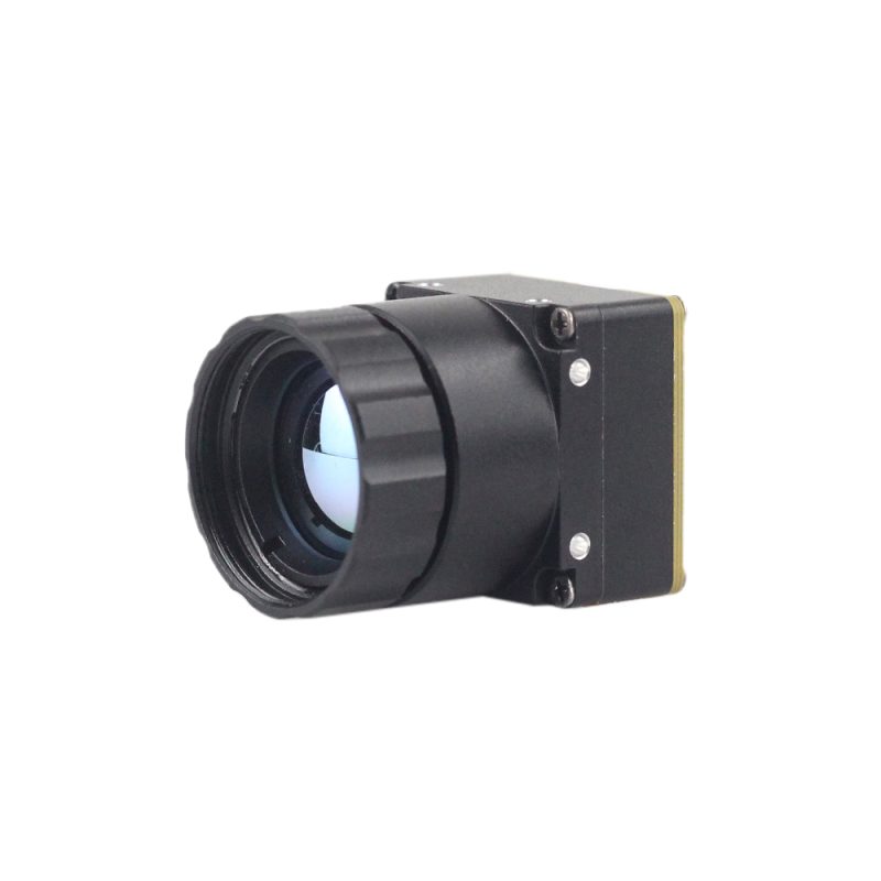
Product Profile: Uncooled LWIR USB Mini 640*512 Thermal Camera Core Module
The Uncooled LWIR USB Mini 640*512 Thermal Imaging Camera Core Module is an ultra-compact thermal imaging core engineered specifically for SWaP-constrained airborne payloads, portable defense optics, and robotics. Featuring an ultra-compact form factor of just 21 mm × 21 mm, this module integrates seamlessly into micro-gimbals similar to DJI platforms without exceeding payload weight budgets.
The core provides sharp, crisp thermal image presentation with low power consumption and high cost efficiency. It supports native 640×512 resolution (with a 640×480 resolution mode optional) and features exceptional optical flexibility, supporting interchangeable fixed-focus lens assemblies spanning 5 mm, 9 mm, 13 mm, 18 mm, 35 mm, 50 mm, 75 mm, 100 mm, and 150 mm. Its USB interface simplifies software integration on embedded Linux, Android, and Windows systems, while delivering stable performance and strong environmental adaptability under harsh vibration and wide ambient temperature fluctuations.

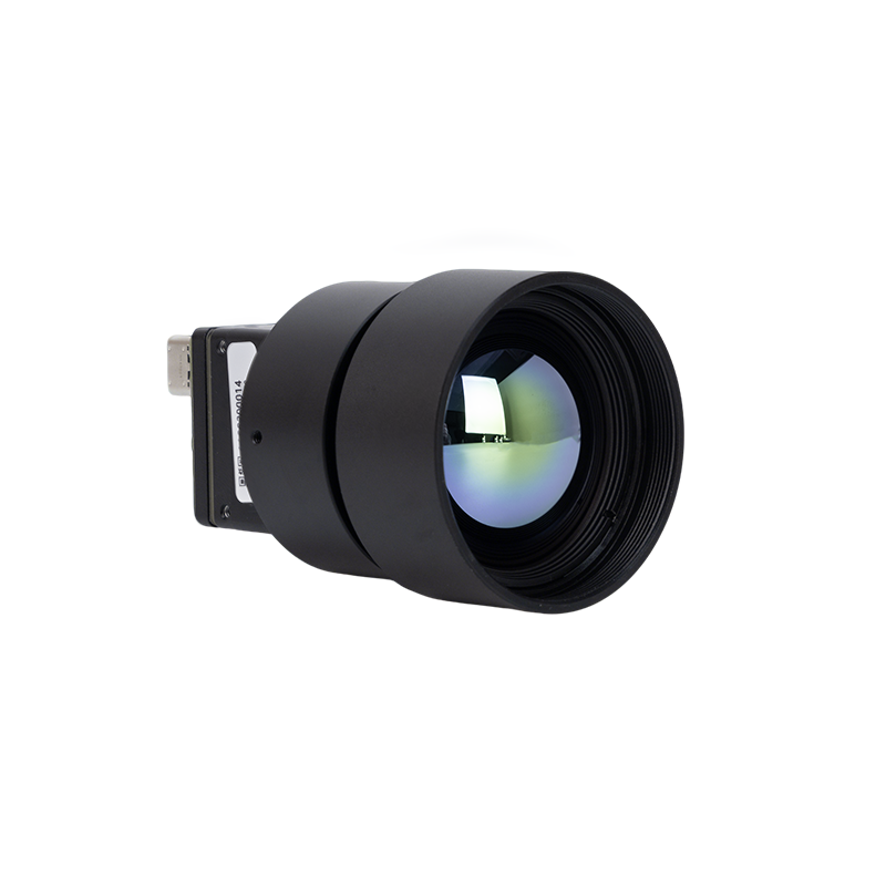
Product Profile: High Resolution Uncooled Infrared 1280*1024 Thermal Imaging LWIR Camera
The High Resolution Uncooled Infrared 1280*1024 Thermal Imaging LWIR Camera is designed for long-range spatial target identification, automated perimeter security, elevated body temperature screening, and precision industrial process control. Boasting an uncooled 1280×1024 mega-pixel focal plane array, this camera core provides four times the pixel density of standard VGA cores, capturing subtle thermal gradients and fine physical structures at long operational standoff distances.
The module comes equipped with a calibrated 25 mm precision athermalized Germanium lens assembly, minimizing thermal defocus across industrial operating envelopes. Its high-resolution VOx detector matrix delivers clean imagery and high sensitivity, making it an ideal candidate for integration with advanced edge AI architectures, high-bandwidth tracking systems, and deep-learning classification pipelines.
To inspect production line calibration procedures, optical cleanroom metrics, and optomechanical quality controls, check the About Our Engineering Team overview.
7. Frequently Asked Questions (Deep-Dive Technical FAQ)
How do I overcome SWaP (Size, Weight, and Power) constraints when integrating thermal sensors into drones or compact edge devices?
Why should we upgrade from low-resolution hobbyist sensors (e.g., 32x24) to industrial 640x512 or 1280x1024 LWIR modules?
What software and protocol support is required for integrating thermal imaging modules into custom vision pipelines?
V4L2_PIX_FMT_Y16) using memory-mapped buffers (V4L2_MEMORY_MMAP) to stream raw, uncompressed 14-bit or 16-bit radiometric data directly into system memory via zero-copy DMA. For camera control, the software stack requires an out-of-band serial control channel over I2C, SPI, or a virtual USB COM port, enabling host software to trigger Flat-Field Correction (FFC), adjust electronic gain modes, and query internal thermistor temperatures. At the application layer, C++ or Python frameworks interface with the stream using OpenCV, GStreamer, or NVIDIA DeepStream/TensorRT. The software pipeline typically bifurcates the incoming stream: one branch applies Plateau Equalization or CLAHE to compress 14-bit frames into 8-bit tensors for neural network inference, while a parallel branch processes 16-bit radiometric values using Planck-based calibration formulas to calculate exact surface temperatures.
📚 References & Further Reading
- Industry Standard: Precision Mezzanine Interconnects — Hirose Electric
- Industry Standard: High-Density Micro Board-to-Board Solutions — Molex
- Related Guide: Uncooled Core Form Factors & Optics — Purpleriver Product Catalog
- Related Guide: Precision Optics for Miniaturized Sensors — Mini2 640x512 Lens Solutions
- Related Guide: Manufacturing Standards & Optomechanical Engineering — About Our Engineering Team