Najlepszy przewodnik po kamerach termowizyjnych: profesjonalna wydajność, Edge AI i praktyczny zwrot z inwestycji
23 października 2026
Najlepszy przewodnik po tanich kamerach termowizyjnych: Budżetowe rdzenie IR do majsterkowania i inspekcji (2025)
Komercyjny rynek termowizji jest zalewany gadżetami konsumenckimi udającymi narzędzia diagnostyczne. Większość kupujących szukających taniej kamery termowizyjnej wpada w pułapkę zakupu smartfonowych przystawek za $250 lub podstawowych urządzeń ręcznych. Te jednostki konsumenckie zazwyczaj mieszczą mikrobolometry o rozdzielczości poniżej VGA (często natywnie zaledwie 80×60 lub 120×90), polegają na agresywnych algorytmach mieszania krawędzi, aby ukryć szum czujnika, i zamykają dane termiczne w zamkniętych, powolnych aplikacjach mobilnych. Dla inżynierów utrzymania predykcyjnego, integratorów dronów i deweloperów elektroniki te konsumenckie zabawki nie dostarczają użytecznych, skalibrowanych danych radiometrycznych w rzeczywistych warunkach przemysłowych.
Prawdziwa opłacalność w termowizji nie pochodzi z ograniczania wydajności czujnika; pochodzi z eliminacji marż konsumenckich, plastikowych obudów i zastrzeżonych wyświetlaczy poprzez bezpośrednie pozyskiwanie rdzeni kamer LWIR (długa fala podczerwieni) od producentów OEM. Wykorzystując moduły niechłodzonego tlenku wanadu (VOx) na gołej płytce z surowymi interfejsami USB lub MIPI CSI-2, architekci systemów mogą uzyskać wysokiej klasy rozdzielczość 640×512, czułość termiczną ≤40 mK i wymienną optykę za ułamek tradycyjnych cen urządzeń laboratoryjnych. Ten przewodnik opisuje, jak wybierać, testować i wdrażać budżetowe rdzenie termowizyjne OEM do systemów wbudowanych, ładunków inspekcyjnych lotniczych i diagnostyki laboratoryjnej.
Spis treści
- 👉 Błędne przekonanie o konsumenckich "tanich kamerach termowizyjnych" a rdzenie OEM na gołej płytce
- 👉 Testy inżynieryjne: Ocena specyfikacji budżetowych czujników LWIR
- 👉 Architektury magistral sprzętowych: USB a MIPI CSI-2 dla widzenia brzegowego
- 👉 Porównanie przemysłowych rdzeni budżetowych: Specyfikacje w warunkach rzeczywistych
- 👉 Architektury wdrożeniowe: Ładunki dronów, śledzenie ścieżek PCB i inspekcja HVAC
- 👉 Pogłębione FAQ inżynierskie
Błędne przekonanie o konsumenckich "tanich kamerach termowizyjnych" a rdzenie OEM na gołej płytce
Gdy zespoły inżynieryjne szukają taniej kamery termowizyjnej do integracji z platformami inspekcyjnymi, często napotykają dwie odrębne kategorie rynkowe: gotowe wtyczki konsumenckie (takie jak smartfonowe przystawki USB-C i ręczne pistolety diagnostyczne poniżej $500) oraz przemysłowe rdzenie OEM na gołej płytce. Choć jednostki konsumenckie wydają się atrakcyjne finansowo na komercyjnych platformach detalicznych, ich wewnętrzna architektura sprzętowa ujawnia znaczące ograniczenia, które utrudniają przemysłowe przepływy pracy.
Ręczne urządzenia klasy konsumenckiej obniżają koszty produkcji poprzez oszczędzanie na fizycznej matrycy płaszczyzny ogniskowej (FPA). Zamiast precyzyjnej matrycy mikrobolometrycznej urządzenia te integrują tanie matryce o rozdzielczości zaledwie 80×60 (łącznie 4800 pikseli pomiarowych) lub 160×120 (19 200 pikseli). Aby zamaskować wynikający z tego rozpikselowany obraz termiczny, producenci stosują techniki dynamicznego mieszania obrazu. Proces ten wyodrębnia wysokoczęstotliwościowe przestrzenne szczegóły krawędzi z niedrogiego czujnika kamery CMOS światła widzialnego i nakłada te kontury na rozmyty strumień termiczny o niskiej rozdzielczości.
Chociaż dynamiczne mieszanie krawędzi daje kontur, który wygląda ostro na zintegrowanym ekranie LCD, wprowadza poważne niedokładności pomiarowe w ilościowej termowizji inżynierskiej. Rejestracja obrazu widzialnego zawodzi za każdym razem, gdy zmienia się odległość do celu, generując błędy paralaksy. Co ważniejsze, nałożone kontury wizualne mogą wprowadzić inspektora w błąd: słaba linia optyczna może zostać błędnie zinterpretowana jako gwałtowny gradient termiczny, podczas gdy rzeczywiste anomalie termiczne ukryte między grubymi elementami przestrzennymi mikrobolometru pozostają całkowicie niewykryte.
Drugim fundamentalnym ograniczeniem urządzeń termowizyjnych klasy konsumenckiej jest ich zależność od zamkniętych, stratnych strumieni danych. Urządzenia ręczne i akcesoria do smartfonów zazwyczaj wyprowadzają 8-bitowe strumienie wideo YUV lub skompresowane H.264/MP4. W tym procesie kodowania absolutne dane radiometryczne zebrane przez detektor są trwale konwertowane na dowolne wartości kolorów (takie jak Ironbow, Rainbow lub White Hot) w oparciu o algorytm automatycznej kontroli wzmocnienia (AGC) kamery. Po skompresowaniu dyskretne odczyty fizycznych czujników zostają utracone, co uniemożliwia przetwarzanie radiometryczne po locie, rekonstrukcję absolutnego pola temperatury lub integrację ze zautomatyzowanymi potokami inspekcji wizyjnej.
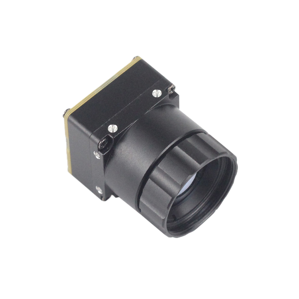
Natomiast rdzenie termowizyjne OEM w wersji bare-board eliminują narzut peryferyjny klasy konsumenckiej. Dzięki wyeliminowaniu plastikowych form wtryskowych, zintegrowanych wyświetlaczy konsumenckich, akumulatorów litowo-jonowych i marż detalicznych stron trzecich, cały koszt jednostkowy jest alokowany bezpośrednio na rdzeń optoelektroniczny: matrycę ogniskową z tlenku wanadu (VOx) lub krzemu amorficznego (α-Si), precyzyjne wewnętrzne przetworniki analogowo-cyfrowe (ADC), mechanizmy migawki korekcji niejednorodności (NUC) działające w czasie rzeczywistym oraz wysokoprzepuszczalne zespoły optyczne z chalkogenidów lub germanu.
Rdzeń OEM zapewnia nieskompresowany 14-bitowy lub 16-bitowy cyfrowy strumień danych bezpośrednio do procesora hosta za pośrednictwem standardowych magistral przemysłowych, takich jak USB 2.0/3.0 lub MIPI CSI-2. W tej architekturze każdy piksel dostarcza jawną wartość cyfrową wprost proporcjonalną do padającego promieniowania podczerwonego docierającego do tego punktu detektora. Inżynier wbudowany zachowuje pełną kontrolę nad macierzami kalibracyjnymi, korekcją transmisji atmosferycznej, kompensacją emisyjności oraz migawkami korekcji niejednorodności.
Dla inżynierów systemowych projektujących bezzałogowe systemy powietrzne (UAS), specjalistyczne stanowiska testowe typu benchtop lub rozproszone węzły ciągłego monitorowania procesów, rdzenie OEM w wersji bare-board zapewniają znaczące korzyści w zakresie rozmiaru, masy, mocy i kosztu (SWaP-C). Usunięcie zbędnych wyświetlaczy i obudów daje moduł rdzenia o wymiarach zaledwie 21 mm × 21 mm i masie poniżej 20 gramów. Umożliwia to ciasną integrację z gimbalami pan-tilt-zoom (PTZ), efektorami końcowymi robotów lub kompaktowymi obudowami elektrycznymi bez przekraczania ścisłych limitów ładowności lub obwiedni termicznych. Aby ocenić niskopoziomowe zagadnienia elektromechaniczne związane z integracją tych kompaktowych silników, zapoznaj się z naszym szczegółowym przewodnik integracji rdzenia kamery termicznej.
Testy inżynieryjne: Ocena specyfikacji budżetowych czujników LWIR
Wybór przystępnego cenowo rdzenia kamery termowizyjnej wymaga oceny niskopoziomowych parametrów elektrooptycznych względem docelowej obwiedni operacyjnej. Ograniczenia budżetowe często wymuszają kompromisy; wiedza o tym, które parametry decydują o wydajności inspekcji, zapewnia, że oszczędności kosztów nie podważą podstawowej niezawodności systemu.
Krytyczne parametry czujników w zamówieniach długofalowej podczerwieni (LWIR)
An optical core must be evaluated across four primary domains: Spatial Resolution (detector elements), Optical Instantaneous Field of View (IFOV), Thermal Sensitivity (Noise Equivalent Temperature Difference, NETD), and Sensor Pixel Pitch (which dictates optomechanical volume and raw optical cost).
Native FPA Resolution and Spatial Analysis
The native resolution of an infrared focal plane array determines the total number of independent temperature sensing points across the target scene. Thermal imaging resolutions follow distinct tiers:
- ⚙️ 256×192 (49,152 pixels): The practical baseline for functional electrical diagnostics and close-range benchtop circuit analysis. At working distances under 0.5 meters, a 256×192 sensor reliably isolates hot spots on individual discrete SMD components such as SOIC-8 ICs or power inductors.
- ⚙️ 384×288 (110,592 pixels): A versatile mid-tier industrial standard. It offers more than double the pixel count of entry-level sensors, providing an excellent balance between data throughput, processing requirements, and optical clarity for structural inspection and industrial machinery monitoring.
- ⚙️ 640×512 (327,680 pixels): The gold standard for professional aerial thermography, utility distribution auditing, and automated industrial visual inspection. With nearly seven times the resolution of a 256×192 core, a 640×512 imager resolves fine structural details at long operational standoffs, making it possible to conduct aerial solar farm surveys or high-voltage transmission substation evaluations from safe distances.
Spatial resolution is directly tied to the Chwilowe pole widzenia (IFOV), which defines the physical spatial area observed by a single detector pixel as a function of optical focal length. The mathematical relation is expressed as:
To obtain an accurate, un-averaged radiometric measurement (rather than simply detecting an object's presence), the target feature must span at least a 3×3 pixel array on the sensor—a metric known as the Measurement Field of View (MFOV). If your optical system yields an IFOV of 1.33 mrad, a single pixel covers a 1.33mm spot at a 1-meter working distance. Accurately measuring temperature on that target requires a minimum physical feature size of approximately 4mm × 4mm (3×3 pixels). A low-resolution sensor forces the operator closer to energized or hazardous equipment to achieve this measurement threshold, introducing safety risks and logistical challenges.
Pixel Pitch: 12μm vs. 17μm Architectures
Older generation uncooled microbolometers utilized a 17μm or 25μm pixel pitch. Modern production nodes have transitioned to 12μm architectures. Shrinking the pixel pitch decreases the overall silicon footprint of the focal plane array. For instance, a 640×512 array with a 17μm pitch measures 10.88mm × 8.70mm diagonally, whereas a 12μm array measures only 7.68mm × 6.14mm.
Because Germanium (Ge) optics represent a significant cost component in LWIR thermal cameras due to raw material and precision single-point diamond turning (SPDT) manufacturing costs, a smaller FPA format allows the use of significantly smaller lens elements to achieve the identical angular Field of View (FOV). This reduction lowers both the bill-of-materials cost and overall optical weight, making 12μm cores particularly well suited for mass-critical payloads such as multi-rotor drone gimbals.
Czułość termiczna: Równoważna szumowi różnica temperatur (NETD)
Noise Equivalent Temperature Difference (NETD) represents the temperature difference that produces a signal-to-noise ratio of unity across the detector array. Expressed in milliKelvins (mK), lower values signify a sensor capable of resolving finer, more subtle temperature variations:
- 🔍 NETD ≤ 50mK: The acceptable standard for heavy electrical inspections, high-friction mechanical bearing failures, and high-contrast heating loads where temperature differentials (ΔT) routinely exceed 10°C.
- 🔍 NETD ≤ 40mK or ≤ 30mK: Essential for building science, low-temperature HVAC leak detection, composite delamination inspection, and circuit board copper trace thermal dissipation profiling. In these applications, the target anomalies often exhibit ΔT values of less than 0.5°C against ambient backgrounds. A sensor with an NETD of ≤40mK clearly delineates these subtle shifts, whereas an inferior ≥70mK sensor displays only static noise.
Frame Rates, Dynamics, and Export Controls
Thermal cameras are subject to strict international regulatory frameworks, specifically the International Traffic in Arms Regulations (ITAR) and Export Administration Regulations (EAR) in the United States, alongside equivalent Dual-Use controls internationally. To prevent uncooled microbolometers from being adapted into guided munitions, thermal sensors operating at frame refresh rates exceeding 9Hz (typically 25Hz, 30Hz, 50Hz, or 60Hz) are subject to stringent export oversight.
Consumer devices often cap their frame rate at 8.7Hz or 9Hz to bypass these export classifications, allowing global retail distribution. However, an 8.7Hz frame rate introduces significant motion latency, rolling shutter tearing, and severe image blur on moving platforms. For drone mapping missions or dynamic automated inspection lines, a 25Hz or 50Hz native core is vital to ensure stable geometric mapping and prevent motion-induced measurement errors.
Architektury magistral sprzętowych: USB a MIPI CSI-2 dla widzenia brzegowego
Integrating a bare-board LWIR module requires matching the hardware bus interface to the computational architecture of your host processing platform. The two primary communication interfaces encountered in modern budget-friendly cores are USB (Universal Serial Bus) and MIPI CSI-2 (Mobile Industry Processor Interface Camera Serial Interface 2).
The USB Bus: Versatility, Rapid Prototyping, and Industrial Computing
Thermal modules equipped with standard USB 2.0 or USB Type-C high-speed interfaces integrate an onboard bridge microcontroller that handles physical bus signaling, packaging the raw analog-to-digital FPA readouts into structured USB bulk packets or standard USB Video Class (UVC) streams.
Primary Advantages:
- ✅ Universal Host Interoperability: USB modules interface natively with x86 industrial PCs, standard laptops, and desktop computing environments, as well as Linux-driven single-board computers (such as the Raspberry Pi 4/5, Odroid, and Intel NUC) without requiring custom PCB daughtercards.
- ✅ Standardized Software Interfaces: On Linux-based platforms, the camera stream can be exposed via the standard Video4Linux2 (V4L2) driver framework. This architecture enables developers to query device capabilities, adjust basic exposure parameters, and pull video frames using standard system calls.
- ✅ Simplified Cabling & Isolation: USB cables provide power delivery (5V VBUS) and differential data transmission across a single four-conductor or Type-C shielded cable. This reduces wiring complexity over distances of 1 to 3 meters within large inspection enclosures.
Engineering Trade-offs: USB introduces software stack latency, non-deterministic packet transmission times, and continuous CPU interrupt overhead. In resource-constrained micro-drones or closed-loop robotic flight stabilization systems requiring sub-millisecond reaction times, the USB host controller stack can consume valuable processing overhead.
MIPI CSI-2: Ultra-Low Latency, Direct Memory Access, and Edge AI
The MIPI CSI-2 protocol provides a high-speed, direct differential serial interface linking the thermal core directly to the host processor's Image Signal Processor (ISP) or application processing core (such as the NVIDIA Jetson Orin Nano/NX, Rockchip RK3588, or NXP i.MX8 platforms).
Primary Advantages:
- ✅ Direct Hardware DMA Streaming: The MIPI D-PHY interface streams raw thermal data frames directly into system RAM via Direct Memory Access (DMA) controllers. This architecture bypasses intermediate microcontroller bridges, protocol transformations, and operating system scheduling delays.
- ✅ Minimal Latency & Zero CPU Overhead: Because frame transfer occurs independently of the CPU instruction cycle, edge devices maintain high processing availability for computer vision tasks, real-time object detection models (e.g., YOLOv8), or dynamic flight control loops.
- ✅ Zoptymalizowany profil SWaP: Eliminating USB physical transceiver ICs, microcontrollers, and oversized connectors reduces the module's mass to the absolute minimum—a crucial benefit for stabilized drone gimbals. For a deeper technical perspective on low-overhead embedded routing, consult our engineering guide to 640x512 MIPI thermal module architecture.
Engineering Trade-offs: MIPI CSI-2 lines operate with high-frequency differential signals requiring carefully calculated trace impedance matching (typically 100Ω differential) and length matching across lane pairs. Cable lengths are generally limited to under 15–20 centimeters without using specialized FPD-Link or GMSL serializer/deserializer (SerDes) bridges. Additionally, deploying MIPI cores requires writing or compiling custom Linux kernel device tree overlays (DTS) and sensor drivers compatible with the host SoC.
Software Interfacing: Building a Custom Radiometric Computer Vision Pipeline
Once a bare-board core is connected to the host system via USB (V4L2) or MIPI, the primary engineering objective is extracting the native 14-bit radiometric counts and converting those integer values into accurate temperature matrices. Unlike consumer thermal imagers that present only colored visual displays, access to the raw 14-bit array allows direct mathematical manipulation of the scene using open-source tools such as OpenCV.
The following Python implementation demonstrates how an industrial edge processor captures an uncompressed 14-bit radiometric feed via V4L2, converts the raw digital counts into degrees Celsius using sensor-specific calibration multipliers, and automatically extracts overheating regions on an active circuit board:
import cv2
import numpy as np

# Initialize video capture using V4L2 backend for raw 16-bit / 14-bit data stream
# Ensure the camera node corresponds to the raw radiometric endpoint
cap = cv2.VideoCapture(0, cv2.CAP_V4L2)

# Request raw 16-bit grayscale format (Y16 / UNCOMPRESSED RAW)
cap.set(cv2.CAP_PROP_FOURCC, cv2.VideoWriter_fourcc(*'Y16 '))
cap.set(cv2.CAP_PROP_CONVERT_RGB, 0)
cap.set(cv2.CAP_PROP_FRAME_WIDTH, 640)
cap.set(cv2.CAP_PROP_FRAME_HEIGHT, 512)

if not cap.isOpened():
    raise IOError("Failed to initialize interface with the OEM thermal core.")

print("Radiometric pipeline successfully established. Processing real-time thermal matrix...")

try:
    while True:
        ret, raw_frame = cap.read()
        if not ret:
            print("Dropped frame or bus synchronization timeout.")
            continue

        # Sensor Calibration Conversion:
        # Many uncooled LWIR cores output raw digital numbers (DN) where:
        # Temperature (Kelvin) = DN * 0.04 (or specific manufacturer scale factor)
        # Temperature (Celsius) = (DN * 0.04) - 273.15
        temp_celsius = (raw_frame.astype(np.float32) * 0.04) - 273.15

        # Query frame-level thermal statistics
        min_temp = np.min(temp_celsius)
        max_temp = np.max(temp_celsius)
        mean_temp = np.mean(temp_celsius)

        # Dynamic Thresholding: Identify localized electronic shorts exceeding 80.0°C
        overheat_threshold = 80.0
        _, anomaly_mask = cv2.threshold(temp_celsius, overheat_threshold, 255, cv2.THRESH_BINARY)
        anomaly_mask = anomaly_mask.astype(np.uint8)

        # Extract spatial contours of thermal anomalies
        contours, _ = cv2.findContours(anomaly_mask, cv2.RETR_EXTERNAL, cv2.CHAIN_APPROX_SIMPLE)

        for cnt in contours:
            x, y, w, h = cv2.boundingRect(cnt)
            peak_fault_temp = np.max(temp_celsius[y:y+h, x:x+w])
            print(f"CRITICAL ANOMALY: Component at X:{x}, Y:{y} (Size: {w}x{h}px) reading {peak_fault_temp:.2f} C")

        # Normalize 14-bit radiometric matrix into 8-bit visual spectrum for operator display
        display_frame = cv2.normalize(temp_celsius, None, 0, 255, cv2.NORM_MINMAX)
        display_frame = np.uint8(display_frame)
        colorized_thermal = cv2.applyColorMap(display_frame, cv2.COLORMAP_INFERNO)

        # Highlight detected overheating regions with bounding boxes on visual output
        for cnt in contours:
            x, y, w, h = cv2.boundingRect(cnt)
            cv2.rectangle(colorized_thermal, (x, y), (x+w, y+h), (0, 255, 0), 2)
            cv2.putText(colorized_thermal, f"{np.max(temp_celsius[y:y+h, x:x+w]):.1f}C",
                        (x, y - 5), cv2.FONT_HERSHEY_SIMPLEX, 0.4, (0, 255, 0), 1)

        cv2.imshow("Automated Thermal Inspection Stream", colorized_thermal)
        if cv2.waitKey(1) & 0xFF == ord('q'):
            break

finally:
    cap.release()
    cv2.destroyAllWindows()
Porównanie przemysłowych rdzeni budżetowych: Specyfikacje w warunkach rzeczywistych
To eliminate consumer markups while retaining full radiometric accuracy, engineering teams turn to direct-manufacturer OEM modules. The following uncooled LWIR camera cores offer professional 640×512 resolution, ultra-compact form factors, and modular optics, providing viable, budget-conscious alternatives to commercial packaged cameras.
Niechłodzony miniaturowy moduł kamery termowizyjnej LWIR USB 640*512

to cud inżynierii zaprojektowany specjalnie do środowisk o ograniczonych parametrach SWaP. Dzięki miniaturyzacji elektroniki bez poświęcania jakości sensora dostarczamy rdzeń, który mieści się w najciaśniejszych przestrzeniach. Moduł rdzeniowy Mini 640 USB is an ultra-compact uncooled infrared thermal engine engineered for applications requiring high spatial resolution, low power consumption, and direct cross-platform computer interfacing. With an ultra-miniature cross-sectional profile of only 21mm × 21mm, this unit integrates seamlessly into tight enclosures, industrial machine vision rigs, and lightweight custom drone gimbals.
The core features an uncooled Vanadium Oxide (VOx) focal plane array capturing 640×512 pixels (with optional 640×480 configurations) across the standard 8μm to 14μm long-wave infrared atmospheric transmission window. It delivers sharp, high-contrast imagery with consistent environmental adaptability, functioning reliably across wide industrial temperature swings.
A notable feature of this core is its extensive optical versatility. System integrators can match the imager to their specific Instantaneous Field of View requirements by selecting from a broad range of factory-aligned athermalized lenses: 5 mm, 9 mm, 13 mm, 18 mm, 35 mm, 50 mm, 75 mm, 100 mm i 150 mm. Whether configured with a 5mm wide-angle lens for wide-area electronic circuit board overviews or a 150mm telephoto optic for long-range powerline surveillance, the Mini 640 maintains stable image geometry and radiometric response.
| Parametr specyfikacji | Hardware Rating |
|---|---|
| Typ detektora | Uncooled VOx Microbolometer (8–14 μm) |
| Rozdzielczość matrycy | 640×512 pixels (640×480 resolution optional) |
| Wymiary modułu | 21mm × 21mm ultra-miniature footprint |
| Interchangeable Optics | 5 mm, 9 mm, 13 mm, 18 mm, 35 mm, 50 mm, 75 mm, 100 mm, 150 mm |
| Host Interface | Direct USB (High Speed Data & Power) |
| Docelowe wdrożenia | Embedded vision, benchtop PCB diagnostics, UAV gimbals |
2. Uncooled Infrared MIPI Mini2 640×512 9mm Thermal Imaging Camera Module

to cud inżynierii zaprojektowany specjalnie do środowisk o ograniczonych parametrach SWaP. Dzięki miniaturyzacji elektroniki bez poświęcania jakości sensora dostarczamy rdzeń, który mieści się w najciaśniejszych przestrzeniach. Mini2 MIPI Core Module is engineered specifically for SWaP-constrained embedded applications, such as lightweight multirotor inspection drones, micro-gimbals, and high-speed robotic edge processors. By leveraging a high-bandwidth MIPI CSI-2 interface, the Mini2 streams uncompressed thermal frames directly into the host SoC's memory pipeline with near-zero bus latency.
Equipped with a compact 9mm athermalized infrared lens, the Mini2 balances spatial resolving power with a wide field of view, making it ideal for aerial reconnaissance, search and rescue operations, and automated agricultural health mapping. The underlying sensor architecture is versatile, supporting 640×512 high-resolution operation, with configurable factory options for 384×288 and 256×192 array configurations to match specific bandwidth and processing budgets.
Weighing only a few grams, the Mini2 eliminates peripheral conversion circuitry, drawing minimal power directly from the carrier board's regulated low-voltage rails. Its bare-board form factor allows engineers to mount the core directly onto custom carbon-fiber airframes or inside sealed sub-assemblies while maintaining direct access to 14-bit radiometric data streams.
| Parametr specyfikacji | Hardware Rating |
|---|---|
| Typ detektora | Uncooled VOx LWIR Microbolometer |
| Native Array Options | 640×512 (Configurable to 384×288 / 256×192) |
| Installed Optic | 9mm Athermalized Germanium / Chalcogenide Lens |
| Interfejs sprzętowy | MIPI CSI-2 (Direct High-Speed ISP Bus) |
| Główna platforma docelowa | UAV payloads, autonomous robotics, edge AI SBCs |
| Charakterystyka obrazu | Sharp edge presentation, low fixed-pattern noise, wide dynamic range |
For specialized installations requiring extended perimeter surveillance or standoff industrial monitoring, custom long-range optics can be integrated into high-performance cores. For an analysis of high-magnification systems, review our technical breakdown on long-range 90mm AI thermal module design.
Architektury wdrożeniowe: Ładunki dronów, śledzenie ścieżek PCB i inspekcja HVAC
Scenario A: Lightweight UAV Thermal Gimbal Payloads
Commercial turnkey thermal drones from leading consumer brands frequently command prices between $5,000 and $10,000, placing them out of reach for small engineering consultancies and educational research teams. A custom radiometric drone payload can be developed at a fraction of that cost by integrating an uncooled MIPI or USB core module into an open-source airframe.
The system architecture utilizes the Mini2 640×512 9mm MIPI module mounted inside a custom 3D-printed carbon-nylon enclosure, balanced on a lightweight 2-axis or 3-axis brushless gimbal. Power is supplied through a step-down DC-DC switching regulator (BEC) tapping the drone's primary flight pack, providing a clean, noise-filtered 5V/3A DC bus to prevent switching motor noise from coupling into the sensitive microbolometer readout circuit.
The MIPI lines route directly into a compact companion single-board computer—such as a Raspberry Pi Compute Module 4 (CM4) or a Radxa Zero 3W. The companion computer executes a lightweight background script that records the raw 14-bit radiometric stream to an onboard high-endurance Class 10 U3 microSD card. Concurrently, it extracts a normalized visual stream, applies an onboard temperature-color palette along with telemetry text overlays (displaying GPS coordinates, altitude, and peak detected temperature), and feeds the composite video out via Micro-HDMI into a digital video transmission system (such as DJI O3 Enterprise or HDZero) for long-range real-time pilot viewing.
Scenario B: Automated Electronics Diagnostic Bench
In high-density electronics development and repair, detecting micro-shorts on power distribution networks (PDNs) presents a common troubleshooting challenge. A shorted multilayer ceramic capacitor (MLCC) or an internally damaged IC may generate only a few milliwatts of parasitic heat, causing a subtle temperature rise (ΔT < 1.5°C) that is easily masked by ambient thermal dissipation across large copper ground planes.
By mounting the Miniaturowy rdzeń USB 640 to an adjustable vertical microscope stand and pairing it with a short-focal-length optic or an auxiliary macro lens, engineers can build a high-resolution benchtop thermal diagnostic station. The core connects to an engineering workstation running an automated diagnostic script.
When current is injected into the board's power rail via a benchtop DC supply, the software captures a reference thermal frame at T=0 and continuously subtracts that baseline from incoming frames. This differential thermography method highlights rapid, localized micro-temperature changes while filtering out stable ambient heat sources, allowing developers to pinpoint shorted components in seconds without using messy freeze sprays or relying on guesswork.
Scenario C: Industrial Electrical Switchgear & Facilities Auditing
Industrial predictive maintenance requires documenting and tracking thermal performance across three-phase distribution panels, motor control centers (MCCs), and plant HVAC infrastructure. Standard handheld diagnostic tools require an operator to manually aim the unit, depress a trigger, and record separate visual and thermal photographs, transcribing data points into spreadsheets by hand.
An OEM core simplifies and automates this workflow. Connected via a flexible, strain-relieved USB interface to an IP67-rated industrial tablet running Linux or Windows, the core functions as an automated continuous thermal auditor. As the technician inspects an electrical cabinet, an automated edge computer-vision algorithm tracks three-phase connections, identifies maximum temperatures for Phase A, B, and C, calculates delta-T phase imbalances, and automatically flags violations of international maintenance standards (such as NETA MTS). The full 14-bit radiometric images and associated temperature matrices are automatically archived to a local database, eliminating manual transcription errors and speeding up facility-wide inspections.
Pogłębione FAQ inżynierskie
Are cheap thermal cameras in the $200-$400 range actually worth buying for HVAC and home inspection?
Why should tech enthusiasts and makers choose a thermal camera core module over an all-in-one handheld unit?
Can an affordable thermal imaging module accurately detect human body temperature and PCB hot spots?
📚 Referencje i dalsza lektura
- Standard branżowy: Real-time computer vision and image processing documentation via OpenCV
- Powiązany przewodnik: Comprehensive mechanical, electrical, and optical przewodnik integracji rdzenia kamery termicznej
- Powiązany przewodnik: High-bandwidth embedded system implementation of 640x512 MIPI thermal module architecture
- Powiązany przewodnik: Optomechanical considerations for long-range 90mm AI thermal module design